Table of Contents
Advertisement
Quick Links
AcuCam
Concept IV
PC
®
INTRAORAL CAMERA FOR THE PERSONAL COMPUTER
Operation Manual and Installation Guide
DENTSPLY International, Inc.
GENDEX Division
901 W. Oakton Street
Des Plaines, IL 60018-1884, USA
(800) 800-2888
(847) 640-4800
(847) 640-6165 (Fax)
www.gendexxray.com
www.dentsply.com
PC
Concept IV
Intraoral Camera System: User Manual, P/N 570134 Rev 0
Advertisement
Table of Contents

Related Manuals for Gendex Dentsply AcuCam Concept IV PC


Summary of Contents for Gendex Dentsply AcuCam Concept IV PC
- Page 1 AcuCam Concept IV ® INTRAORAL CAMERA FOR THE PERSONAL COMPUTER Operation Manual and Installation Guide DENTSPLY International, Inc. GENDEX Division 901 W. Oakton Street Des Plaines, IL 60018-1884, USA (800) 800-2888 (847) 640-4800 (847) 640-6165 (Fax) www.gendexxray.com www.dentsply.com Concept IV...
-
Page 2: Table Of Contents
6.2.2. Replacing the Power Fuses Section 3 — Installation and Wiring Repair Equipment Positioning Considerations Docking Station Installation Section 7 — DENTSPLY Gendex Limited Wiring the Concept IV System Warranty Section 4 — Operating Instructions ANNEX A — If You Need Assistance... -
Page 3: Section 1: Safety Requirements
Dentsply-Gendex Technical Support at 1-800-769-2909, or your “NOTE:” refers to any operation, procedure, or local Dentsply contact listed in Appendix A. - Page 4 Sheaths. AcuCam disposable sheaths were properly installed and operating prior to designed specifically for the Concept IV contacting Dentsply or Gendex for technical handpiece. It is recommended that only AcuCam support. sheaths be used in conjunction with the AcuCam...
- Page 5 1.3. DEFINITION OF SYMBOLS Below are the definitions of symbols which are used with this product. NOTE: Includes Type BF Applied Part NOTE: Grounded Medical Equipment, Type B CAUTION: Replace Fuse As Marked CAUTION: Refer to Manual WARNING: Electric Shock Hazard. Do Not Remove Cover. Refer Servicing to Qualified Service Personnel.
- Page 6 Gendex for technical support. The Concept IV is precisely factory set to produce high resolution, full-color, S-video and 2.3. PRODUCT INTRODUCTION ®...
- Page 7 ® AcuCam Concept IV and Concept IV Intraoral Camera Systems Key features of the AcuCam Concept IV Camera System: • Ergonomically-designed handpiece with slim distal end for complete intraoral access. • State-of-the-art optical system with an adjustable focus range of 1 mm to infinity. •...
- Page 8 2.4. GETTING TO KNOW YOUR ACUCAM CONCEPT IV ® 2.4.1. Unpacking System Components ------------------------------------------------------------------------ ® The AcuCam Concept IV system is carefully CAUTION: Report any damaged components inspected and packaged prior to shipment. If the to the shipping company and any missing Concept IV was shipped to you, please components to your dealer within 24 hours of...
- Page 9 ® 2.4.3 The AcuCam Concept IV Handpiece ----------------------------------------------------------------- The AcuCam Concept IV camera handpiece is a optical system into a lightweight and portable sophisticated dental instrument designed to handpiece. The ergonomically designed provide the highest quality intraoral and extra- handpiece is the product of 15 years of oral images.
-
Page 10: Docking Station
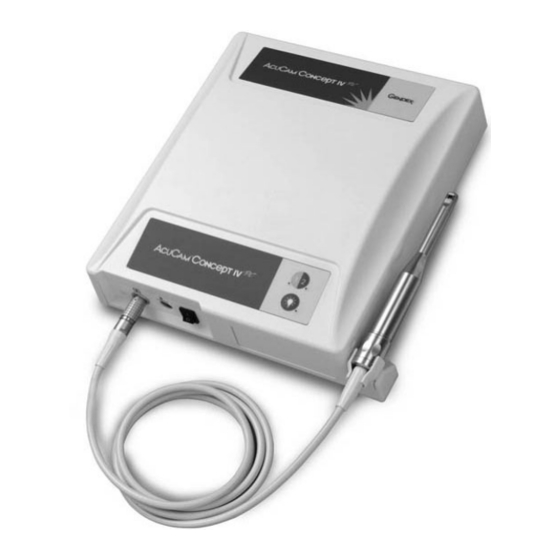
2.4.4. The Concept IV Docking Station --------------------------------------------------------------------- The Concept IV docking station is the system and output connections. Please see the pictures hub with which the camera connects to all other below to identify the key features of the docking components of the system. - Page 11 Video 1/Video 2 Selector Switch Video 1 LED Video 2 LED (Concept IV Camera) (Alternative Source) Lamp Power Concept IV Membrane Panel Lamp On/Off Switch Concept IV Back Panel (Cover Removed) Connection Type Purpose Foot Switch (8-Pin mini-DIN) Not used for Concept IV Video Out (BNC) Composite video output for analog monitor S-Video Out 1 &...
-
Page 12: Moving, Storage, And Shipping
CAUTION: Originator assumes all liability prior to moving. for damages incurred to equipment during shipment to Dentsply-Gendex for warranty For prolonged periods of non-use, it is or non-warranty repairs. recommended the system and its accessories are 2.6. -
Page 13: Product Specifications
2.7. PRODUCT SPECIFICATIONS Below are the specifications of the product at the right to change the design and specifications at time of printing. Dentsply-Gendex reserves the anytime without notification. Camera Equipment Model AcuCam Concept IV ® Weight 0.4 Kg (0.9 lbs.) Width of Handpiece 19.0 mm (0.75 inch) - Page 14 System—Environmental U.S. Gov’t. Classification— IPXO Ingress Protection U.S. Gov’t. Classification— Medical Grade Console and Power Supply Classification— Cabled camera head, Handpiece Medical Grade Type BF Environmental conditions -10 — 40˚C for transportation and storage Environmental conditions +10 — 40˚C for operation System—Conformance Evaluated to meet the Requirements of the Medical...
-
Page 15: Section 3 - Installation And Wiring
Section 3: Installation, Wiring and Setup 3.1. EQUIPMENT POSITIONING CONSIDERATIONS There are as many ways to set up an intraoral runs so as not to cause a tripping or electrical camera system as there are dental offices. Each hazard. practitioner must decide which setup is most The main monitor should be positioned where comfortable for them taking into account: office the practitioner can get the best view. -
Page 16: Docking Station Installation
As with all imaging devices, lighting has a images, and degrade the contrast of the video profound effect on the resulting images. monitor. Avoid excessive lighting conditions by Excessive outdoor or florescent lighting can providing shades to exterior windows with direct impact the image quality of the extra-oral sunlight, and grids to overhead florescent lights. - Page 17 WARNING: Do not disconnect cable from chassis. If the cable does become disconnected from the chassis, do not attempt to reinstall yourself. Call your local Dentsply-Gendex dealer service representative, local Dentsply office, or Dentsply-Gendex for technical assistance. Remove the Mounting Bracket------------------------------------------------------------------------------------ The Concept IV...
- Page 18 Re-Attach the Docking Station Chassis ----------------------------------------------------------------------- Once the mounting bracket is secured, reattach mounting bracket. Reinstall the two retaining the docking station. Slide the pin on the lower screws through the mounting bracket and into front panel of the docking into the hole in the the chassis.
- Page 19 Position the Holster -------------------------------------------------------------------------------------------------- The holster on the docking station is not attached at the time of delivery. Once you have finished installing your Concept IV Docking Station, you may install the holster. See pictures below for proper orientation of holster. CAUTION: Please be sure the orientation of the holster is correct before snapping it in place.
-
Page 20: Wiring The Concept
3.3. WIRING THE ACUCAM ® CONCEPT IV SYSTEM ® Below is a simplified AcuCam Concept IV signal on the computer monitor. An optional system wiring diagram. The docking station is patient monitor can be connected to the output connected to the computer via the capture card. of the capture card if one is provided. -
Page 21: Section 4: Operating Instructions
Section 4: Operating Instructions 4.1. ATTACHING/DETACHING THE CAMERA TO THE DOCKING STATION The Concept IV handpiece connects to the the fiber optic cables. It is designed to provide docking station via a highly engineered, medical maximum protection and reliability to the grade connector. -
Page 22: Holding The Handpiece
4.3. HOLDING THE HANDPIECE ® The AcuCam Concept IV handpiece is a pencil or a mirror, with the barrel resting inn the sophisticated, ergonomically designed intraoral recess between your index finger and thumb. camera. It can be easily manipulated single- Your index finger and thumb should rest on the handedly while providing complete intraoral dimples at the 10 and 2 o’clock positions. -
Page 23: Focusing The Handpiece
4.4. FOCUSING THE HANDPIECE The focal range of the Concept IV camera is labeled, corresponds to a variable macro setting. divided into four focus settings controlled by the The table below shows each position with its focus ring. The focus ring features three fixed respective focal range, average magnification, positions corresponding to (E)xtraoral, (W)ide, and clinical purpose... -
Page 24: Controlling The Lamp Power
4.5. CONTROLLING THE LAMP POWER Under normal operating conditions, when the handpiece is removed from the holster, the lamp turns on emitting light from the handpiece, and the green Lamp Power LED to the right of the button is illuminated. Pressing the Lamp Power switch turns the lamp and green LED off. -
Page 25: Incorporating The Camera Into The Practice
The illumination and magnification of the unattainable without this technology. intraoral image on the monitor allows greater NOTE: Gendex understands that observation of the condition of the patient’s examination protocol is a highly mouth. Typically, the patient will be observing individualized matter. -
Page 26: Section 5: Cleaning And Infection Control
Dentsply-Gendex, part number 301793. dental practice. Dentsply-Gendex only recommends the use of 5.3. INSTALLING SHEATHS The disposable sheaths are enclosed between exercised when installing the camera handpiece... - Page 27 Step 2 —Insert the Camera Handpiece Insert the camera handpiece such that the lens window is facing DOWN towards the paper backing. Gently slide the camera handpiece completely into sheath. Avoid excessive force when inserting the handpiece into the sheath to prevent rupturing.
-
Page 28: Heat Sterilization
CAUTION: Products that contain iodophors can stain the surface of the Docking Station. Iodophers are not recommended. WARNING: Use of disinfectants for cleaning the camera handpiece does not insure sterilization. Gendex only recommends the barrier method as an effective infection control protocol AcuCam Concept IV User Manual... -
Page 29: Cleaning The Camera Sapphire Window
5.6. CLEANING THE CAMERA SAPPHIRE WINDOW Contaminants on the sapphire window can 2. Shake handpiece to remove excess fluid. impair image quality. Use the following 3. Gently touch the center of the window with procedure to clean the sapphire window. the swab, then using a spiraling motion, wipe the The following agents are acceptable camera and entire surface of the window. -
Page 30: Section 6: Troubleshooting, Maintenance And Repair
Section 6: Troubleshooting, Maintenance and Repair 6.1. TROUBLESHOOTING NOTE: Troubleshooting follows a deductive logic sequence, starting with the simplest solution first. For this reason, basic troubleshooting steps, such as ‘Is power on?’ should not be ignored. Main Symptom Additional Symptoms Possible Cause Troubleshooting / Corrective Action Computer Monitor Problems... - Page 31 Main Symptom Additional Symptoms Possible Cause Troubleshooting / Corrective Action Computer Monitor Problems, continued Effected by Handpiece Call Gendex Technical Support Defective camera cable movement to replace Check for loose connections Docking Station/computer Check Docking Station output with a Computer image OK,...
- Page 32 Main Symptom Additional Symptoms Possible Cause Troubleshooting / Corrective Action Illumination Problems Lamp Power LED lit Defective lamp Replace lamp (see sect. 6.2.1) Handpiece in holster Remove Handpiece from holster No / low Handpiece Lamp power LED not lit illumination No video image on Bright light shining into Cover holster.
- Page 33 Main Symptom Additional Symptoms Possible Cause Troubleshooting / Corrective Action TV / Analog Monitor Problems (connected to the Docking Station or capture card output) Confirm monitor switched On No AC power Check AC source and connection Cables not properly Check for proper connection connected Incorrect monitor input Select appropriate S video or composite...
-
Page 34: Maintenance
602547, 12V 75W halogen bulb, are severe electrical shock. If lamp is hot, allow available from your local Dentsply-Gendex the lamp to cool before removing. dealer. Replacement lamps have an average bulb life of 2,000 hours. - Page 35 Step 3 — Disconnect the Ribbon Cable Gently disconnect the flat ribbon cable from the underside of the cover by pulling it out of the cable connector. Step 4 — Remove Lamp Holder Unscrew and remove the two metal lamp fasteners from the lamp holder.
- Page 36 Step 5 — Lamp in Holder Pull the old lamp out of the lamp holder. Carefully remove the new replacement lamp from its packaging and place in holder. Do not use unprotected hands. Read Caution below. CAUTION: Be sure NOT to touch the new lamp with unprotected hands.
-
Page 37: Replacing The Power Fuses
Step 8 — Replace Cover Reconnect membrane panel ribbon cable by plugging into the connector board. Be sure to orient the label “A” on the cable with the “A” on the connector board. Replace the cover by reversing Steps 1 and 2 of this procedure. 6.2.2. -
Page 38: Repair
If, Most repairs cannot be performed on-site. The however, your system does malfunction, contact unit must be sent back to Dentsply-Gendex for your Dentsply-Gendex dealer service repair. representative, Dentsply-Gendex technical AcuCam Concept IV... -
Page 39: Section 7: Dentsply Gendex Limited Warranty
ORIGINAL PRODUCT. Dentsply-Gendex; or (9) acts of God, acts of civil or military authority, fires, floods, strikes or WARRANTY EXCLUSIONS other labor disturbances, war, riots, or other... - Page 40 The remedies set forth herein are conditioned shall terminate. In no event shall Dentsply- upon Buyer promptly notifying Dentsply- Gendex be liable for special or consequential Gendex within the applicable warranty period of damages. any defect or non-conformance and making the...
-
Page 41: Annex A - If You Need Assistance
ANNEX A If You Need Assistance If you need assistance, first contact your local DENTSPLY Gendex dealer. They have been trained to handle most technical service issues. If you cannot get the information you need there, simply call the Gendex or DENTSPLY office nearest to you. - Page 42 DENTSPLY Mexico Calz. Vallejo 846 02300 Mexico D.F. Tel. +52.5587.6488 Fax +52.5587.8605 Europe EUROPEAN HEADQUARTERS Dentsply Gendex Dentsply Italia srl, Gendex Division Via A. Manzoni 44 20095 Cusano Milanino MI Italia Tel. +39.02.618.0081 Fax +39.02.618.008309 www.dentsply.it GERMANY GENDEX Dental Systeme...
- Page 43 FRANCE DENTSPLY Detrey 17, rue Michael Faraday 78180 Montigny le Bretonneux Tel. +33.1.30147777 Fax +33.1.30147700 UNITED KINGDOM DENTSPLY United Kingdom Hamm Moor Lane, Addlestone Weybridge, Surrey KT15 2SE Tel. +44.1932.853422 Fax +44.1932.840168 South Africa SOUTH AFRICA DENTSPLY S. Africa 197 Biggarsberg Road Glenvista, Ext 6, 2058 Tel.
- Page 44 KOREA DENTSPLY Korea Hyun Woo Building 1 Floor 459-5 Dogok-dong Kangnam-ku, Seoul Tel. +82.2.577.3797 Fax +82.2.577.3798 TAIWAN DENTSPLY Taiwan 7F-11, 351 Sec. 2 Chung-Shan Road Chung-Ho, Taipei County Tel. +886.2.2223.7777 Fax +886.2.2223.7603 THAILAND DENTSPLY Thailand Ltd. Floor Panjathani Tower 127/28 Ratchdapisek Road Chongnonsee, Yannawa Bangkok 10120 Tel.
Need help?
Do you have a question about the Dentsply AcuCam Concept IV PC and is the answer not in the manual?
Questions and answers