Table of Contents
Advertisement
Advertisement
Table of Contents

Related Manuals for Gendex ORTHORALIX 9200 DDE


Summary of Contents for Gendex ORTHORALIX 9200 DDE
- Page 1 User Manual 9200 DDE/Plus/Ceph Panoramic X-ray...
- Page 2 X-ray equipment may cause injury if used improperly. The instructions contained in this manual must be read and followed when installing, servicing, or operating the Orthoralix® 9200 DDE. The Orthoralix 9200 DDE provides a high degree of protection from unnecessary X-radiation. However, no practical design can provide complete protection, nor prevent operators from exposing themselves or others to unnecessary radiation.
-
Page 3: Table Of Contents
Table of Contents Chapter 1 - About this Manual Intended Use ................. 1-2 Conventions Used in this Manual ........... 1-2 Trademarks Used in this Manual ............ 1-3 Chapter 2 - System Description Major Components ................ 2-2 Labels - Location and Descriptions ..........2-6 Accessories ................... - Page 4 System Icons ................6-12 Status Icon ....................6-12 GX Driver Icon .................... 6-14 Chapter 7 - Standard Pan Projection Prepare the Orthoralix 9200 DDE ........... 7-1 Prepare Patient ................7-5 Place Patient into Position ................7-5 Adjust Patient’s Head Position ..............7-7 Make Exposure ................
- Page 5 Patient Positioning ..................8-4 Frontal TMJ ................... 8-5 Operation ....................8-6 Patient Positioning ..................8-6 Frontal Dentition ................8-6 Maxillary Sinuses, Frontal View ............. 8-7 Left and Right Maxillary Sinus, Lateral View ........8-7 Operation ..................... 8-7 Chapter 9 - Problem Prevention and Solutions Correcting Image Distortions ............
- Page 6 Orthoralix 9200 DDE Host Unavailable ..................9-10 Host Busy ....................9-10 Chapter 10 - Ceph Projections Prepare the Orthoralix 9200 DDE ..........10-2 Prepare the patient ..............10-7 Latero-Lateral, Antero-Posterior, and Postero-Anterior ....... 10-7 Carpus ....................... 10-9 Make the exposure ..............10-9 Setting the soft tissue filter ............
- Page 7 Modality: BASIC ................B-1 Modality: DMF ................B-2 Modality: CEPH ................B-3 Modality: TRANSCAN ..............B-4 Appendix C - X-ray Projection Geometries Appendix D - Manufacturer’s Declaration Appendix E - Classification and Standards Classification ................. E-1 Standards ..................E-1 Appendix F - Multi-room Management Multi-room Function ..............
- Page 8 Orthoralix 9200 DDE -viii 032-0275-EN Rev 1...
-
Page 9: Chapter 1 - About This Manual
Chapter About this Manual This manual contains original instructions that describe the Gendex Orthoralix 9200 DDE X-ray image acquisition system that operates in real time. The radiographic geometric projections provided by the Orthoralix 9200 DDE system are of greatest interest for dentists, surgeons, and maxillo-facial radiologists. -
Page 10: Intended Use
Orthoralix 9200 DDE Intended Use This manual is intended to assist the user in the safe and efficient operation of the equipment described. The equipment must be used in accordance with the procedures contained in the manual and must not be used for purposes other than those which are described herein. -
Page 11: Trademarks Used In This Manual
• Gendex® and Orthoralix® are Registered Trademarks of Gendex Dental Systems • VixWin™ Platinum is a trademark of Gendex Dental Systems • Microsoft®, Windows®, Windows2000®, WindowsXP®, Windows Vista®, are registered trademarks of Microsoft Corporation in the United States and other countries... - Page 12 Orthoralix 9200 DDE 032-0275-EN Rev 1...
-
Page 13: Chapter 2 - System Description
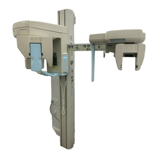
Chapter System Description The Orthoralix 9200 DDE connected to a computer comprises the system. The system provides panoramic radiography of the dento-maxillo-facial area. When the ceph assembly is attached to the column, the system can provide cephalometric radiography. (See page 2-4.) A variety of geometric projections for different diagnostic purposes are available in both panoramic and cephalometric modes. -
Page 14: Major Components
Orthoralix 9200 DDE Major Components Most components in the system are part of the motorized rotating imaging assembly. The rotating imaging assembly is mounted to the counter-balanced motorized column (fixed to the wall or to an optional free-standing base). Independent, microprocessor-controlled stepper motors control the movement of the rotating imaging assembly as it moves around the patient’s... - Page 15 System Description In preparation for the panoramic exposure, the motorized rotating imaging assembly is moved out of the way allowing the patient to move into the initial position. The headrest, hand grip, bite guide, and positioning mirror are used to establish the initial patient position. Lasers aid in establishing the final position of the patient’s head.
- Page 16 Orthoralix 9200 DDE The ceph assembly option adds the components required for cephalometric radiolography: 5. Ceph CCD sensor 1. Ceph control panel 6. Release buttons on the sensor 2. Ceph arm 7. Power LED 3. Secondary collimator 4. Cephalostat 032-0275-EN Rev 1...
- Page 17 System Description The nasion support and ear rods aid in positioning the patient’s head. The knob is turned to fix or release the nasion support. The lever for the nasion support moves it forward or backward. The lever for the ear rods moves them in or out.
-
Page 18: Labels - Location And Descriptions
Orthoralix 9200 DDE Labels - Location and Descriptions 032-0275-EN Rev 1... - Page 19 System Description Label Description System ID Manufacturer and responsible INPUT VOLTAGE REQUIREMENTS LONG TERM RATING MAX. MOMENTARY RATING Primary Collimator ID CERTIFICATION Product complies with radiation performance standards under the Federal Food, Drug, and Cosmetic Tubehead ID CERTFICATION Product complies with radiation performances standard under the Federal Food, Drug, and Cosmetic Sensor ID...
- Page 20 Orthoralix 9200 DDE Laser Aperture LASER RADIATION DO NOT STARE INTO BEAM CLASS II LASER PRODUCT 650nm, 1mWI EC60825-1 Ed.2 (2007) Symbol Description IEC Label Type B: Protection against electrical shock (IEC 60601-1) Caution Consult written instructions in this Manual.
-
Page 21: Accessories
System Description Symbol Description Mains Hot Wire Mains Neutral Wire Accessories Catalog No. Description P13362 Hygienic cover for bite guide (pkg of 100) P20211 Bite guide P20221 Chin rest P20952 Hygienic covers for cephalometric ear plugs (280 ct) P21191 Chin rest for TMJ projection 032-0275-EN Rev 1... - Page 22 Orthoralix 9200 DDE 2-10 032-0275-EN Rev 1...
-
Page 23: Chapter 3 - Safety
The equipment must never be used if there are any electrical, mechanical, or radiation defects whatsoever. Modifications and additions to the equipment must be carried out only by Gendex personnel or third parties that are expressly authorized by Gendex, and must comply with the applicable legal requirements as well as with the generally accepted technical regulations. -
Page 24: Electrical Safety
Orthoralix 9200 DDE Electrical Safety Only qualified service personnel should remove the covers or otherwise obtain access to parts of the system. The system may only be used in rooms which comply with the relevant national and/or international legislation and recommendations (for example, CE and others) concerning electrical safety in rooms used for medical purposes. - Page 25 Safety The position of laser sources are identified by means of the following warning labels (black on yellow). C A U T I O N LASER RADIATION DO NOT STARE INTO BEAM Wavelength: 650nm, output Power ≤1mW Complies with FDA performance standards for laser products except for deviations pursuant to Laser Notice No.
-
Page 26: Anatomical Reference Indications
Orthoralix 9200 DDE Anatomical Reference Indications Once the Pan procedure has been performed, positioning references (L and R) will be displayed on the acquired image: • L (Left) to indicate the left side of the patient’s mouth • R (Right) to indicate the right side of the patient’s mouth On symmetrical images, both L and R are displayed. -
Page 27: Proper Disposal Of Electronic Equipment
Safety Proper Disposal of Electronic Equipment NOTE: The following information is valid in the European Union. If you wish to discard this product, please contact your local authorities or dealer and ask for the correct method of disposal. This symbol on the products and/or accompanying documents means that used electrical and electronic products should not be mixed with general household waste. - Page 28 Orthoralix 9200 DDE 032-0275-EN Rev 1...
-
Page 29: Chapter 4 - Cleaning And Disinfection
Chapter Cleaning and Disinfection Protect the Patient All parts coming in direct contact with the patient must be kept clean and disinfected. Always substitute the disposable hygienic covers of the bite guide and ear plugs before positioning a new patient. These covers should be stored in a clean, dry environment and not exposed to direct sunlight or UV radiation. - Page 30 Orthoralix 9200 DDE CAUTION It is not recommended to use spray disinfectants as the disinfectants may permeate into the system and cause short circuits or corrosion. If an atomizer is used for disinfection, follow the procedure provided below to protect the system.
-
Page 31: Chapter 5 - System Startup And Shutdown
Chapter System Startup and Shutdown Turn System On 1. Turn on the system by pressing the power switch under the handgrip. 2. Ensure that the computer/software is activated. NOTE: If the CCD sensor has not been installed, see page 5-3 for instructions to install the sensor before continuing. -
Page 32: Turn System Off
Orthoralix 9200 DDE 3. Wait until “dE” is no longer seen in the mA display and press Reset. If the above mentioned operations have been carried out correctly, the system has been reset. The Ready LED on the main control panel lights up to indicate the reset condition. -
Page 33: Install/Release Ccd Sensor
Pan sensor housing or in the Ceph sensor housing. When the Orthoralix 9200 DDE is equipped with the Cephalometric assembly, it’s necessary to take out the sensor from the Pan sensor housing and install the sensor in the Ceph sensor housing. -
Page 34: Release
Orthoralix 9200 DDE Release To release the sensor, grab the sensor securely with both hands and press the release buttons. The clicking sound indicates the lateral pins have released. Rotate the top of the sensor module towards you to a 45° angle. Pull until the guide posts are out of the guide post channels and remove the sensor. -
Page 35: Chapter 6 - Controls And Indicators
Chapter Controls and Indicators Power Switch Refer to the System Start Up and Shutdown section for the location of the power switch. Main Control Panel Each button on the control panel is labeled with a pictogram related to the associated function. The operator does not use more than one button to initiate a given function. - Page 36 Orthoralix 9200 DDE Cephalography mode selected Transcan mode selected Panoramic mode selected kV Increase kV for the next exposure kV Decrease kV for the next exposure mA Increase mA for the next exposure mA Decrease mA for the next exposure Increase exposure time (s) for the next s...
-
Page 37: Select Projection
Controls and Indicators Select Projection When the system is turned on, the Standard Pan projection is set and the relevant button LED lights up. You can go to Standard Pan at any time by pressing the button. To select the other exposure modalities, press the or .buttons. -
Page 38: Automatic Exposure Control (Aec)
Orthoralix 9200 DDE Automatic Exposure Control (AEC) The default setting for the AEC mode is off. Press this button to activate AEC mode. The AEC mode can be selected for the following projections: • Standard panoramic • Child panoramic •... -
Page 39: Set Technique Factors
Controls and Indicators Set Technique Factors The exposure technique factors related to the chosen selection (kV, mA, seconds) will be set and displayed. If the operator deems it necessary, kV and mA can be individually modified (each in the whole range) by pressing the following keys: + kV, - kV, + mA, - mA, in the upper part of the control panel. -
Page 40: Patient Positioning Controls
Orthoralix 9200 DDE Patient Positioning Controls Headrest Controls Use these two buttons to either open or close the patient headrest arms. Rotating Imaging Assembly Height Controls When positioning the patient in the machine, use the up and down buttons to move the rotating imaging assembly up or down. -
Page 41: Lasers Control
Controls and Indicators Constant pressure for more than 2 seconds will cause either of these buttons to gradually accelerate until the movement is at the maximum speed. To move the rotating imaging assembly in increments of one millimeter, press and release the button as many times as required. -
Page 42: Demo Mode
Orthoralix 9200 DDE Demo Mode CAUTION As the demo mode most often is followed directly by the actual exposure, remove all metal articles (glasses, removable dentures, earrings, etc.) before positioning the patient. If he/she is to be fitted with a lead-lined apron for radiation protection, make sure that the neck is not covered, because this will cause unexposed areas in the radiograph. -
Page 43: Ceph Control Panel
Controls and Indicators Ceph Control Panel Ceph control panel 1. Down button - Moves the ceph assembly down. 2. Up button - Moves the ceph assembly up. CAUTION Do not continue to use the unit if pressing either the up or down button fails to move the ceph assembly. -
Page 44: Primary Collimator Settings
Orthoralix 9200 DDE Primary Collimator Settings The available settings on the collimator change the collimation of the X-ray beam according to the selected projection. When the projection is selected, the corresponding LED on the main control panel will light up. Refer to page 6- 1 for a description of the LEDs on the main control panel. -
Page 45: Settings For Ceph Projections
Controls and Indicators Settings for Ceph Projections Set the primary collimator to one of two Ceph mode positions: LL Horizontal (18 x 24 cm) Vertical format (22 x 18 cm): - LL Vertical - AP/PA Vertical Maximum format (22 x 24 cm): - LL Max - AP/PA Max The Ceph symbol on the main control panel lights up. -
Page 46: Exposure Handswitch
This green and blue icon indicates the correct operation of the Orthoralix 9200 DDE electronics (including the CCD sensor), the connection between the Orthoralix 9200 DDE and the CCD sensor, and the connection between the Orthoralix 9200 DDE and the computer or networking device. - Page 47 - Sensor calibration required Small red X: CCD sensor not present Magnifying glass: Connection problem somewhere in the system Red: Orthoralix 9200 DDE is not present on the network Yellow X: Computer/networking device connected but does not have control 032-0275-EN Rev 1...
-
Page 48: Gx Driver Icon
Orthoralix 9200 DDE GX Driver Icon When the Gendex driver is installed correctly, the GX icon is shown in the system tray. Right-click this icon to display a menu for viewing and modifying data and parameters common to all the Gendex imaging system products. -
Page 49: Chapter 7 - Standard Pan Projection
• Select the standard Pan projection Next the patient is prepared: • Properly position the patient in the Orthoralix 9200 DDE • Adjust the patient’s head position The exposure is made. NOTE: A quick reference guide indicating the options/actions necessary to perform a standard panoramic exposure is located on the right side of the column near the control panel. - Page 50 Orthoralix 9200 DDE NOTE: The message COLLIMATOR is displayed if the CCD sensor has been inserted in the Ceph sensor housing and the collimator is set to the Pan position. 2. Check that kV and mA values appear in the display.
- Page 51 Standard Pan Projection The LED at the side of icon lights up and the message STND PANORAMIC is displayed. 3. Press Reset. 4. Press the Patient size selection button. There are three patient size selections: 032-0275-EN Rev 1...
- Page 52 Orthoralix 9200 DDE • small (small young lady or teenager) • medium (average size female or male) • large (large adult male or elderly person with calcified mandible) NOTE: Medium size patient is selected by default. 5. If necessary, modify the preset exposure factors. (See page 6-5.) 6.
-
Page 53: Prepare Patient
Standard Pan Projection Prepare Patient Place Patient into Position NOTE: To help calm a nervous patient (for example, children) use the demo mode to demonstrate the movement of the rotating imaging assembly. (Refer to page 6-8.) 1. Open the headrest arms. 2. - Page 54 Orthoralix 9200 DDE 4. Place the patient close to the bite guide (or transparent chin rest). The bite guide must be at the level of patient’s mouth (occlusal plane) or, the transparent chin rest must be aligned with the patient’s chin.
-
Page 55: Adjust Patient's Head Position
Standard Pan Projection 6. If using the bite guide, ensure that the patient is not biting too far forward (beyond the groove). NOTE: Edentulous patients should use the transparent chin rest. Instead of using the bite guide, the patient can bite down on a cotton roll so as to align lower and upper incisors. - Page 56 Orthoralix 9200 DDE 1. Switch on the positioning lasers. NOTE: The lasers are timed and they will switch off automatically after 30 s. NOTE: If the laser does not switch on, check the status icon in the Windows system tray....
- Page 57 Standard Pan Projection 3. Use the lever at the right side of the mirror to align the horizontal light beam with the lower margin of the orbit. WARNING In step 4, raise and lower the rotating imaging assembly slowly. The patient can be hurt if the rotating imaging assembly moves too fast.
-
Page 58: Make Exposure
Make sure the patient does not shift position during the exposure process. 3. Verify the correct system status icon displays in the system tray: Orthoralix 9200 DDE is ready to capture the images 7-10 032-0275-EN Rev 1... - Page 59 Standard Pan Projection NOTE: The exposure handswitch button must be kept firmly pressed during the entire exposure procedure. Otherwise X-ray emission and rotating imaging assembly movements will be stopped (“dead man” exposure mode). If this should happen, the unit must be reset, the patient must be re-positioned, and the exposure must be repeated.
- Page 60 Orthoralix 9200 DDE 5. When the exposure cycle has been concluded, release the exposure handswitch button. The final image is transferred to the imaging software. 6. At the conclusion of the scan, the headrest arms will automatically open. Ask the patient to move out.
-
Page 61: Chapter 8 - Other Panoramic Projections
Chapter Other Panoramic Projections Press the Projection Selection buttons to scroll through the set of projections. The name of the selected projection is shown in the display. Refer to Appendix B, Technique Factors, for the factory settings for each projection. For the X-ray projection geometries, refer to Appendix C, X-ray Projection Geometries. -
Page 62: Orthogonal Dentition
Orthoralix 9200 DDE Orthogonal Dentition Description Orthogonal dentition is a panoramic projection limited solely to the dentition, without the rami and the TMJ. The orthogonality of the X-ray beam to each single element of the dentition is better than in a conventional Standard Panoramic projection in the entire dento-maxillo-facial area. -
Page 63: Left-Half Panoramic And Right-Half Panoramic
Other Panoramic Projections Left-Half Panoramic and Right-Half Panoramic (These projections are named LEFT JAW and RIGHT JAW on the main control panel display.) Description These specific projections of the respective sides of the mouth are recommended for a careful reproduction and also for a reduced radiological load if the object being diagnosed is included in one of the dental arches. -
Page 64: Patient Positioning
Orthoralix 9200 DDE Patient Positioning NOTE: Positioning the patient with the special skull cephalostat for TMJ provides optimal image congruence (careful positioning and reproducibility). 1. Position the patient with the white chin rest (without the ridge). 2. Place the ear plug of the TMJ ruler in the right auditory meatus. -
Page 65: Frontal Tmj
Other Panoramic Projections 4. Move the patient’s head back and forth until the cuspid light coincides with the vertical line in the TMJ ruler. The center of the fossa should be about 75 mm behind this light beam. The angle between the major condylar axis and the perpendicular to the median/sagittal plane... -
Page 66: Operation
Orthoralix 9200 DDE Operation In the TMJ projection, the longitudinal pre-positioning displacement of the rotating imaging assembly is inhibited, and the equipment always starts the exposure cycle from the reset position at Y = 7 mm. Patient Positioning NOTE: Positioning the patient with the special skull cephalostat for TMJ is strongly recommended. -
Page 67: Maxillary Sinuses, Frontal View
Other Panoramic Projections Maxillary Sinuses, Frontal View Description The Frontal sinus projection provides a linear scannography of the skull in postero-frontal view, at the level of the nasal sinuses. Depending on the area of interest in the sinus, you can change the position of the image layer by pressing the button (7 mm backward) or button (7 mm forward). - Page 68 Orthoralix 9200 DDE 032-0275-EN Rev 1...
-
Page 69: Chapter 9 - Problem Prevention And Solutions
It is the owner’s responsibility to arrange for this service, and to assure that personnel performing this are fully qualified to service Gendex dental X-ray equipment. It is recommended that the Preventive Maintenance checks as listed in the supplied Installation/Maintenance Manual be performed at the time of installation and every twelve months thereafter. -
Page 70: Proper Patient Positioning
If the image remains distorted, repeat the above steps. There are no limitations on the number of times an image can be resent. If this does not resolve the issue, please contact Gendex Technical Support at 1-800-323-8029. Proper Patient Positioning When images are distorted, ensure proper procedures are being employed. - Page 71 Problem Prevention and Solutions Examples of common positioning errors follow. Problem: Head turned to the left. Result: The left side is magnified, the right side is diminished. Problem: Head tilted too far forward. Result: The occlusion plane is very curved, ascending rami sloping together.
- Page 72 Orthoralix 9200 DDE Problem: Head tilted too far backward. Result: The occlusion plane is flat, ascending rami diverging. Often the hard palate will obscure the upper root apices. Problem: Patient standing too far forward of cuspid light beam. Result: The length of the image is shortened and the central incisors are compressed.
- Page 73 Problem Prevention and Solutions Problem: Patient standing too far back of cuspid light beam. Result: The length of the image is expanded and the central teeth are enlarged. 032-0275-EN Rev 1...
-
Page 74: Back Up Patient Image Data
In particular, it is important to configure a correct combination between the Orthoralix 9200 DDE and the personal computer. Therefore, the other electrically connected parts (computer and optional peripherals) shall be located outside from the patient area, and should be in conformity with IEC 60950-1, UL 60950-1, CSA C22.2 No. -
Page 75: Network Card
Problem Prevention and Solutions Network Card An Ethernet 10/100 base T network card must be installed. Monitor To ensure correct viewing of the images, a multisync color monitor with high resolution capable of displaying 800x600 min., or 1024x768 pixels, is recommended. -
Page 76: Density Test
AEC Default Enable/disable the AEC default function when powering-up the Orthoralix 9200 DDE. Default Values Reset default values on the Orthoralix 9200 DDE. Messages and Alarms A number of warning messages may be displayed in case of certain anomalous conditions:... -
Page 77: Cooling Down
DMU Fault No image is acquired under X-ray. No Connection The physical connection between the Host PC and the Orthoralix 9200 DDE is lost. DMU Not Detected The serial number of the DMU (CCD sensor) is not detected. -
Page 78: Transfer Error
A DMU transmission error is not recovered after 3 image resend. HW Fault ### (Where ### is a specific error code) An HW fault in one of internal Orthoralix 9200 DDE communication bus (PA7). Host Unavailable There is no logical connection between the Host PC and the Orthoralix 9200 DDE (Multi Room Management). -
Page 79: Chapter 10 - Ceph Projections
Chapter Ceph Projections Ceph projections available on the Orthoralix 9200 DDE are listed in the table below: Latero-Lateral The most common use of the cephalometric Projection extension is to take latero-lateral radiographs of the skull, mostly used to trace a cephalogram for the purpose of orthodontic treatment. -
Page 80: Prepare The Orthoralix 9200 Dde
Ceph assembly to the column of the main gantry. Prepare the Orthoralix 9200 DDE NOTE: Make sure that the Ceph sensor is correctly installed in the Ceph sensor housing before turning on the system. - Page 81 Ceph Projections • If the values are not displayed, press Reset. 3. Select one of the Ceph projections as displayed on the main control panel ensuring that the position of the collimator on the tubehead is consistent with the format of the chosen image: Ceph LL Ceph AP/PA Carpus...
- Page 82 Orthoralix 9200 DDE 4. Press Reset. 5. Press the select patient button and choose between small, medium, or large. 6. If necessary, modify the preset exposure factors. (Refer to page 6-5.) 7. If not already in position, firmly grasp the circular cover of the cephalostat and manually turn it to orient the patient’s head as follows:...
- Page 83 Ceph Projections 8. Fully open the ear rods of the cephalostat, using the lever to the right of the cephalostat. Extract the nasion support fully, using the lever to the left of the cephalostat, and turn the support upwards. • Setup for Latero-Lateral projection •...
- Page 84 Orthoralix 9200 DDE screw that holds the nasion support. Insert the provided screw and tighten to attach. Attach Carpus positioner here 10. If the Ceph CCD sensor housing and the secondary collimator are located at the front of the assembly, in order to facilitate the positioning of the patient, press the button on the Ceph control panel to move the Ceph CCD sensor housing out of the way.
-
Page 85: Prepare The Patient
Ceph Projections Prepare the patient Latero-Lateral, Antero-Posterior, and Postero- Anterior NOTE: To help calm a nervous patient (for example, children) use the demo mode to demonstrate the movement of the Ceph CCD sensor housing and the secondary collimator. (See Demo Mode on page 6-8.) 1. - Page 86 Orthoralix 9200 DDE 4. Use the lever to gently close the ear rods until the ear plugs enter into the acoustic meati. Latero-lateral positioning Antero-posterior positioning NOTE: For latero-lateral projections where the soft tissue filter will be applied, refer to Setting the soft tissue filter on page 10-12 for information about setting the filter.
-
Page 87: Carpus
Ceph Projections the Demo mode button to test. (Refer to Demo Mode on page 6-8 for more information.) Carpus Ask the patient to firmly place the hand on the Carpus positioner, with the target zone corresponding to the transparent zone of the positioner. NOTE: The patient has to stand in a comfortable position, compatible to his/ her physical possibility to maintain it during the examination. - Page 88 Orthoralix 9200 DDE 2. Verify the correct system status icon displays in the system tray: Orthoralix 9200 DDE is ready to capture the images NOTE: The exposure handswitch button must be kept firmly pressed during the entire exposure procedure. Otherwise X-ray emission and carriage movements will be stopped (“dead man”...
- Page 89 Ceph Projections 4. During X-ray emission, preview images are continuously provided for the imaging software to display. For imaging software that provides a preview window, verify the correct image acquisition. 5. When the exposure cycle has been concluded, release the exposure handswitch button.
-
Page 90: Setting The Soft Tissue Filter
Orthoralix 9200 DDE Setting the soft tissue filter Five numbered and graduated segments of increasing size are marked on the cephalostat. The graduated segments correspond to the position of the adjustment lever of the nasion support. To enter this value into the system, press the buttons on the main control panel to increase or decrease the value. -
Page 91: Chapter 11 - Transcan Mode
Chapter Transcan Mode The Transcan projection is specifically intended to be used for implantology. It employs scanographic technology to acquire layered images of operator selected 8 mm thickness perpendicular to the dental arch (transversal plane). Transcan Projections Four projections can be selected on the control panel, offering a complete examination of the dental arches and corresponding alveolar bone sections: •... -
Page 92: Transcan Positioning Device
Orthoralix 9200 DDE Transcan Positioning Device The Transcan positioning device is a prerequisite to assure reliable and reproducible patient positioning. The patient’s dentition impression can be mounted to the device or a dedicated bite guide can be attached to the device. -
Page 93: Positioning Device Templates
Transcan Mode Also included are alignment templates used to set the diagnostic target zone by aligning the patient’s dentition impression (previously obtained with the supplied impression material) with reference points on the alignment templates. The prelimary alignment is done at the workbench along with the patient’s dentition impression (impression must be taken using the supplied tray and molding compound) or a dedicated bite guide. -
Page 94: Maxilla Template
Orthoralix 9200 DDE Maxilla Template Anterior (central and lateral incisor) Left side Right side (green (blue tooth tooth icons) icons) Posterior (molar, pre-molar, canine) 1 = distal slice a = molars 2 = central slice b = premolars 3 = mesial slice... -
Page 95: Mandible Template
Transcan Mode Mandible Template Anterior (central and lateral incisor) Right side Left side (green (blue tooth tooth icons) icons) Posterior (molar, pre-molar, canine) 1 = distal slice a = molars 2 = central slice b = premolars 3 = mesial slice c = cuspids d = incisors 032-0275-EN Rev 1... -
Page 96: Transcan Projection
(For a description of the transcan positioning device and the set of alignment templates, refer to pages 11-2 through 11-5.) Next, the Orthoralix 9200 DDE is prepared: • Attach the postioning device to the Orthoralix 9200 DDE • Ensure that the Pan CCD sensor is installed. •... - Page 97 Transcan Mode 4. Mix equal amounts (half a spoonful) of base and catalyst, place the resulting compound in the tray. 5. Make the dentition impression according to the manufacturer’s instruc- tions. 032-0275-EN Rev 1 11-7...
-
Page 98: Preliminary Alignment
Orthoralix 9200 DDE NOTE: The quantity of compound used to make the impression should be just enough to ensure that the patient can accurately place the dentition impression during X-ray exposure as described in the following pages. Remove any excess compound using an appropriate cutter or other sharp edged tool.... -
Page 99: Align Impression - Upper Jaw
Transcan Mode NOTE: In order to ensure an accurate alignment of the dentition impression relative to the icons on the alignment templates, the angle of observation must be perpendicular to the template itself. Align Impression - Upper Jaw 1. Loosen all fastening screws and ensure that all components of the positioning device are free to move as needed. - Page 100 Orthoralix 9200 DDE NOTE: The position of the tooth icons on the template, which lie outside the sagittal axis, reflect the effective position of single elements relative to jaw morphology. In all cases it is of very important to verify that both the impression tray and the section comprising the diagnostic target are aligned with the inscribed longitudinal axis passing through each tooth icon on the templates.
-
Page 101: Align Impression - Lower Jaw
Transcan Mode Align Impression - Lower Jaw 1. Fit the alignment template for the lower jaw to the holder, inserting the guide pins into the appropriate holes on the positioning device (positioning device is upside-down). 2. While observing the dentition impression through the transparent template and using the vernier slides and rotating carriage (X and Y axis, rotation) of the positioning device, maneuver it into the required position: •... -
Page 102: Align Mandibular Profile
Orthoralix 9200 DDE Align Mandibular Profile Molar Region Reference area on mandible template Diagnostic target zone Target Correct alignment Target 11-12 032-0275-EN Rev 1... - Page 103 Transcan Mode Pre-molar Region Reference area on mandible template Diagnostic target zone Target Target Correct alignment 032-0275-EN Rev 1 11-13...
- Page 104 Orthoralix 9200 DDE Canine Region Reference area on mandible template Diagnostic target zone Target Target Correct alignment 11-14 032-0275-EN Rev 1...
- Page 105 Transcan Mode Incisor Region Reference area on mandible template Diagnostic target zone Target Correct alignment Target 032-0275-EN Rev 1 11-15...
-
Page 106: Prepare The Orthoralix 9200 Dde
Orthoralix 9200 DDE Prepare the Orthoralix 9200 DDE NOTE: Make sure that the CCD sensor (Pan sensor or Ceph sensor) is correctly installed in the Pan sensor housing before turning on the system. (Instructions provided in System Start Up and Shutdown section.) 1. - Page 107 Transcan Mode • If the values are displayed, continue to the next step. Select one of the Transcan projections as displayed on the main control panel: • RR Posterior • RR Incisors • LL Posterior • LL Incisors NOTE: In Transcan mode, the button doesn’t have any recalling function.
-
Page 108: Prepare Patient
Orthoralix 9200 DDE 6. Press the select patient button and choose between small, medium, or large. 7. If necessary, modify the preset exposure factors. Prepare Patient Place Patient into Position NOTE: To help calm a nervous patient (for example, children) use the demo mode to demonstrate the movement of the rotating imaging assembly. - Page 109 Transcan Mode 4. Place the patient close to the bite guide (or transparent chin rest). The bite guide must be at the level of patient’s mouth (occlusal plane) or, the transparent chin rest must be aligned with the patient’s chin. 5.
-
Page 110: Position Patient's Head
Orthoralix 9200 DDE Position Patient’s Head 1. If using the impression tray for patient positioning, reposition the impression on the patient’s dental arch making certain that all teeth are in their correct position. 2. If using the special Transcan bite guide, have the patient bite on the special bite guide, making sure that the incisors fit into the appropriate splines on the bite guide. -
Page 111: Make Exposure
Release when one of these touches the head of the patient. 2. Verify the correct system status icon displays in the system tray: Orthoralix 9200 DDE is ready to capture the images 032-0275-EN Rev 1... - Page 112 Orthoralix 9200 DDE NOTE: The exposure handswitch button must be kept firmly pressed during the entire exposure procedure. Otherwise X-ray emission and rotating imaging assembly movements will be stopped (“dead man” exposure mode). If this should happen, the unit must be reset, the patient must be re-positioned, and the exposure must be repeated.
- Page 113 Transcan Mode 6. If the headrest arms were closed, they will automatically open. Ask the patient to move out. 7. Reset the system. To process the final image, refer to the manual for your imaging software. 032-0275-EN Rev 1 11-23...
- Page 114 Orthoralix 9200 DDE 11-24 032-0275-EN Rev 1...
-
Page 115: Chapter 12 - Technical Test Phantom
Chapter Technical Test Phantom A patented universal technical test phantom (part number 4519 124 20471) is available and supplied as an accessory with every Orthoralix 9200. This is used to measure the most important geometrical parameters of images in panoramic mode. The phantom consists of a molded object that incorporates a radio-opaque curved line. - Page 116 Orthoralix 9200 DDE • The deviation of the image layer provided by the equipment, with respect to the average standard curve for the dentition, can be assessed by observing the radiographic shape of the vertical segments. In case of perfect coincidence (both in shape and...
- Page 117 Technical Test Phantom Standard average jaw shape for dentition. 032-0275-EN Rev 1 12-3...
- Page 118 Orthoralix 9200 DDE 12-4 032-0275-EN Rev 1...
-
Page 119: Chapter 13 - Aec Mode
Chapter AEC MODE AEC (automatic exposure control) is a real-time control of the dosage necessary to compensate for spine absorption at the center of the image, varying the pre-set kV factor for the selected patient size. The actual momentary kV in other parts of the exposure may be different from this maximum value in order to account for the different levels of absorption. -
Page 120: Viewing Aec Kv Corrections
Orthoralix 9200 DDE Press the select patient size button and choose the appropriate size to set and display the optimum technique factors for that exposure (kV, mA, s). Refer to Set Technique Factors on page 6-5. Viewing AEC kV Corrections At the end of the exposure, the operator can verify the maximum value of corrections made during the scan. -
Page 121: Appendix A - Technical Data
Appendix Technical Data For diagrams and detailed technical information, refer to the Service Manual. Power supply input voltage: 120 Vac or 230 Vac nominal, 115-250 Vac Frequency: 48-62Hz Line regulation at 115 Vac: Max. line power rating: 10A at 230V, 20A at 115V Line current absorption in stand-by: <... - Page 122 Orthoralix 9200 DDE approximate average 0.325 mGy/s at 70 kV, Output dose rate: 10mA, 1m Leakage radiation from tubehead: less than 250 μGy/hour (84kV) at 1 m in any direction Leakage technique factors: 84 kV, 15 mA, duty factor 1:20 ND.
-
Page 123: Modality: Basic
Appendix Technique Factors Modality: BASIC Preset technique factors 1.25 0-14 Standard panoramic 1.25 0-14 Child panoramic 1.25 0-14 Orthogonal dentition 23.5 1.25 0-14 Left Jaw (Left Half- panoramic) 23.5 1.25 0-14 Right Jaw (Right Half- panoramic) 1.23 0-14 Lateral TMJ (open/close mouth) 1.25 0-14... -
Page 124: Modality: Dmf
Orthoralix 9200 DDE Modality: DMF Preset technique factors 1.25 0-14 Left Half- Orthogonal (Left Orthogonal Half- dentition) 1.25 0-14 Right Half- Orthogonal (Right Orthogonal Half- dentition) 1.24 0-14 Frontal sinuses 1.27 Lateral sinus (Left) 1.27 Lateral sinus (Right) 1.64 Frontal TMJ... -
Page 125: Modality: Ceph
Modality: CEPH Preset technique factors Latero – Lateral (LL) Latero – Lateral (LL H) Latero – Lateral (LL Max) Antero – Posterior (AP/PA V) Antero – Posterior (AP/PA 20.5 Max) Carpus 1.03 032-0275-EN Rev 1... -
Page 126: Modality: Transcan
Orthoralix 9200 DDE Modality: TRANSCAN RR posterior 1.337 LL posterior 1.337 RR incisors 1.337 LL incisors 1.337 032-0275-EN Rev 1... -
Page 127: Appendix C - X-Ray Projection Geometries
Appendix X-ray Projection Geometries Standard panoramic Typical radiograph Child panoramic Typical radiograph 032-0275-EN Rev 1... - Page 128 Orthoralix 9200 DDE Orthogonal dentition Typical radiograph Left jaw (left half-panoramic) Typical radiograph Right jaw (right half-panoramic) 032-0275-EN Rev 1...
- Page 129 Lateral TMJ (open/close mouth) Typical radiograph Frontal dentition Typical radiograph 032-0275-EN Rev 1...
- Page 130 Orthoralix 9200 DDE Right half- orthogonal Typical radiograph Left half- orthogonal Frontal sinuses Typical radiograph 032-0275-EN Rev 1...
- Page 131 Lateral sinus - right Typical radiograph Lateral sinus - left Frontal TMJ Typical radiograph 032-0275-EN Rev 1...
- Page 132 Orthoralix 9200 DDE 032-0275-EN Rev 1...
-
Page 133: Appendix D - Manufacturer's Declaration
Gendex Orthoralix 9200 DDE. The Gendex Orthoralix 9200 DDE should not be used adjacent to or stacked with other equipment. If adjacent or stacked use is necessary, the Gendex Orthoralix 9200 DDE should be observed to verify normal operation in the configuration in which it will be used. - Page 134 Guidance and manufacturer’s declaration – electromagnetic emissions The Gendex Orthoralix 9200 DDE is intended for use in the electromagnetic environment specified below. The customer or the user of the Gendex Orthoralix 9200 DDE should assure that it is used in such an environment.
- Page 135 Table 202 - Guidance and manufacturer's declaration - electromagnetic immunity for all EQUIPMENT and SYSTEMS Guidance and manufacturer’s declaration - electromagnetic immunity Gendex Orthoralix 9200 DDE is intended for use in the electromagnetic environment specified Gendex Orthoralix 9200 DDE below. The customer or the user of the should assure that it is used in such an environment.
- Page 136 Guidance and manufacturer’s declaration – electromagnetic immunity The Gendex Orthoralix 9200 DDE is intended for use in the electromagnetic environment specified below. The customer or the user of the Gendex Orthoralix 9200 DDEshould assure that it is used in such an environment.
- Page 137 RF communications equipment and the Gendex Orthoralix 9200 DDE The Gendex Orthoralix 9200 DDE is intended for use in an electromagnetic environment in which radiated RF disturbances are controlled. The customer or the user of the Gendex...
- Page 138 Orthoralix 9200 DDE 032-0275-EN Rev 1...
-
Page 139: Appendix E - Classification And Standards
Appendix Classification and Standards Classification Orthoralix 9200 DDE is a Class 1 and Type B electromedical X-ray equipment according to IEC 60601-1. Orthoralix 9200 Film is classified in Class IIB according to the European Council Directive for medical devices 93/42/CEE. - Page 140 Modifications and/or additions to the equipment may only be carried out by Gendex or by third parties expressly authorized by Gendex to do so. Such changes must comply with legal requirements as well as with the generally accepted technical rules....
-
Page 141: Appendix F - Multi-Room Management
Multi-room Management Multi-room Function The Multi-room function gives the possibility to grab the image acquired with the device on different PCs connected in a Local Area Network (LAN). In order to have this function available, Active X driver has to be installed on multiple networked PC's and one of the connected PCs has to be selected as a recipient for the image acquisition. -
Page 142: Icons
Orthoralix 9200 DDE Only 1 PC at a time will be enabled to take the control of the DDE, automatically disabling this possibility for the other PC's in the net. Icons After the installation of the ActiveX driver on a PC connected in the Orthoralix DDE's network, in the system tray of Windows (in the "application bar"... -
Page 143: Network Inspection Through The Main Tab
(including multiple resend). On the user's request the following message is prompted "This PC cannot take control of the Orthoralix 9200 DDE at this time. Try later.” When the PC controlling the Orthoralix is switched-off the control is moved to the default PC in the connectable network, otherwise ( i f no default PC is present) no other PC can automatically take the control. - Page 144 Orthoralix 9200 DDE 032-0275-EN Rev 1...
- Page 146 Hatfield, PA 19440 USA D-88400 Biberach, Germany Customer Service: 1-800-323-8029 Tel: +49 7351 56 0 Fax: 1-847-550-1322 Fax: +49 7351 56 1488 Technical Support: 1-800-769-2909 e-mail: info@kavo.de Fax: 1-847-718-0716 www.gendex.com ©2011 Gendex Dental Systems, 032-0275-EN Rev 1 2011 April 1...
Need help?
Do you have a question about the ORTHORALIX 9200 DDE and is the answer not in the manual?
Questions and answers