Table of Contents
Advertisement
Quick Links
Advertisement
Table of Contents

Subscribe to Our Youtube Channel
Related Manuals for IFM Electronic Efector 100 GG711S


Summary of Contents for IFM Electronic Efector 100 GG711S
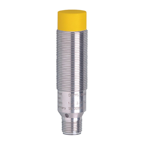
- Page 1 Original operating instructions Fail-safe inductive sensor GG711S ...
-
Page 2: Table Of Contents
Contents 1 Preliminary note ���������������������������������������������������������������������������������������������������3 1�1 Explanation of symbols ����������������������������������������������������������������������������������3 2 Safety instructions �����������������������������������������������������������������������������������������������4 2�1 Safety-related requirements regarding the application ����������������������������������4 3 Items supplied������������������������������������������������������������������������������������������������������5 4 Functions and features ����������������������������������������������������������������������������������������5 5 Functions �������������������������������������������������������������������������������������������������������������6 5�1 Enable zone ���������������������������������������������������������������������������������������������������6 6 Installation������������������������������������������������������������������������������������������������������������7 7 Electrical connection ��������������������������������������������������������������������������������������������8 7�1 Operation as 4-wire unit ��������������������������������������������������������������������������������8 7�2 Operation as 3-wire unit ��������������������������������������������������������������������������������8 8 Operation �������������������������������������������������������������������������������������������������������������9... -
Page 3: Preliminary Note
1 Preliminary note The instructions are part of the unit� They are intended for authorised persons according to the EMC and Low Voltage Directive and safety regulations� The instructions contain information about the correct handling of the product� Read the instructions before use to familiarise yourself with operating conditions, installation and operation�... -
Page 4: Safety Instructions
2 Safety instructions • Follow the operating instructions� • Improper use may result in malfunctions of the unit� This can lead to personal injury and/or damage to property during operation of the machine� For this reason note all remarks on installation and handling given in these instructions� Also adhere to the safety instructions for the operation of the whole installation�... -
Page 5: Items Supplied
► Adhere to the principle of normally closed operation for all external safety circuits connected to the system� ► In case of faults within the fail-safe sensor which result in the defined safe state: take measures to maintain the safe state when the complete control system continues to be operated�... -
Page 6: Functions
5 Functions LEDs fail-safe sensor close zone enable zone safe switch-off distance s damping element Yellow signal LED: switching status Green power LED: operating voltage 5.1 Enable zone The outputs (OSSD) are only enabled when a damping target is present in the enable zone�... -
Page 7: Installation
Depending on the characteristics of the damping element there may be no close zone� 6 Installation The unit can be non-flush mounted according to IEC 60947-5-2, type I2A18SP2� ► Ensure the unit cannot work loose� Maximum tightening torque: 30 Nm ►... -
Page 8: Electrical Connection
7 Electrical connection ► Disconnect power� Also disconnect any independently supplied relay load circuits� ► Supply voltage: connect L+ to pin 1 and L– to pin 3 of the connector� The nominal voltage is 24 V DC� This voltage may vary between 19�2 V and 30 V incl�... -
Page 9: Operation
In case of operation as 3-wire unit only A2 must be used as output (OSSD). Otherwise the safety function of the sensor will be impaired or prevented. ► Connect output A1 to supply voltage� ► Make absolutely sure to exclude cross faults and short circuits between the supply voltage and output A2 by means of appropriate installation! The indicated values regarding the safety function (→ 10 Technical data) remain unchanged�... -
Page 10: 8�2 Response Times
8.2 Response times Response time on safety request ≤ 1 ms (removal from the enable zone) Response time when approaching the enable zone ≤ 1 ms (enable time) Risk time / response time for safety-related faults ≤ 20 ms Simultaneity of switching on and off of the outputs in case of a safety ≤... -
Page 11: Scale Drawing
9 Scale drawing 70,5 LED 2 x 180° 10 Technical data GG711S GIGA4008-2PS/SIL2/V4A/US Fail-safe inductive sensor Metal thread M18 x 1 M12 connector Enable zone: ≤ 1 ��� ≥ 8 mm Conforms to the requirements of: SIL 2 to IEC 61508, SILcl 2 to IEC 62061, PL d to EN ISO 13849-1 non-flush mountable Operating voltage 24 V DC (19�2���30 V) - Page 12 Response time response time on safety request (removal from the enable zone) ≤ 1 ms response time when approaching the enable zone (enable time): ≤ 1 ms Risk time (response time for safety-related ≤ 20 ms faults) Power-on delay time Safe switch-off distance s >...
- Page 13 Wiring (BN) +24 V (WH) (BU) (BK) Evaluation unit or PLC Core colours: BK: black BN: brown BU: blue WH: white Remarks: Unless stated otherwise, all data refer to the 24 x 24 x 1 mm reference target plate to IEC 60947-5-2 (FE360 = mild steel) over the whole temperature range�...
-
Page 14: Troubleshooting
11 Troubleshooting → 8�3 LED display Problem Possible cause Troubleshooting No LED display No voltage supply Apply voltage Power LED flashes and • Undervoltage Correct the voltage sensor does not switch • Overvoltage (→ 10 Technical data) Sensor does not switch, Sensor was brought into the •... -
Page 15: Approvals/Standards
13 Approvals/standards The following standards and directives have been applied: • 2006/42/EC European machinery directive • 2004/108/EC EMC directive • EN ISO 13849-1 PL d (2006) Safety of machinery - Safety-related parts of control systems • IEC 60947-5-2 (2008) low voltage switchgear and controlgear: control circuit devices and switching elements - proximity switches •...
Need help?
Do you have a question about the Efector 100 GG711S and is the answer not in the manual?
Questions and answers