Table of Contents
Advertisement
Quick Links
Advertisement
Table of Contents

Related Manuals for IFM Electronic efector 160 LR8300


Summary of Contents for IFM Electronic efector 160 LR8300
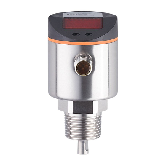
- Page 1 Operating instructions Electronic level sensor LR8300...
-
Page 2: Table Of Contents
Contents 1 Preliminary note ���������������������������������������������������������������������������������������������������4 1�1 Symbols used ������������������������������������������������������������������������������������������������4 2 Safety instructions �����������������������������������������������������������������������������������������������4 3 Items supplied������������������������������������������������������������������������������������������������������5 4 Functions and features ����������������������������������������������������������������������������������������6 4�1 Applications ���������������������������������������������������������������������������������������������������6 4�1�1 Restriction of the application area ��������������������������������������������������������6 5 Function ���������������������������������������������������������������������������������������������������������������7 5�1 Measuring principle ���������������������������������������������������������������������������������������7 5�2 Features of the unit ����������������������������������������������������������������������������������������8 5�2�1 Easy set-up �������������������������������������������������������������������������������������������8 5�2�2 Display functions ����������������������������������������������������������������������������������8 5�2�3 Switching functions �������������������������������������������������������������������������������8... - Page 3 10 Parameter setting ��������������������������������������������������������������������������������������������25 10�1 General parameter setting �������������������������������������������������������������������������25 10�2 Probe length (unit on delivery) �������������������������������������������������������������������27 10�3 Configuration of the display �����������������������������������������������������������������������27 10�4 Selecting the evaluation mode ������������������������������������������������������������������27 10�5 Offset setting ����������������������������������������������������������������������������������������������28 10�6 Setting of output signals ����������������������������������������������������������������������������28 10�6�1 Setting of the output function ������������������������������������������������������������28 10�6�2 Setting of switching limits (hysteresis function) ��������������������������������28 10�6�3 Setting of switching limits (window function) ������������������������������������28 10�6�4 Setting of the switch-off delay �����������������������������������������������������������29...
-
Page 4: Preliminary Note
1 Preliminary note 1.1 Symbols used ► Instructions > Reaction, result […] Designation of pushbuttons, buttons or indications → Cross-reference Important note Non-compliance can result in malfunction or interference� Information Supplementary note� 2 Safety instructions • Please read this document prior to set-up of the unit� Ensure that the product is suitable for your application without any restrictions�... -
Page 5: Items Supplied
140 / 55�1 E43209 160 / 63�0 E43210 Flange plate Size / process connection Order no� 73 - 90 / ¾” NPT E43206 Only use rods from ifm electronic gmbh� The optimum function is not ensured when using components from other manufacturers�... -
Page 6: Functions And Features
4 Functions and features The unit continuously detects the level in tanks and generates output signals ac- cording to the parameter settings� 4 switching outputs are available� They can be set separately� For correct function the unit needs a large enough metal launching plate� It is necessary for transferring the microwave pulse to the tank with optimum transmission power�... -
Page 7: Function
- Media which are very inhomogeneous, separate from each other thus forming separation layers (e�g� oil layer on water)� ► Check the function by an application test� > In case of signal loss, the unit displays [E�033] and switches the outputs to a defined state (→ 11.5). -
Page 8: 5�2 Features Of The Unit
5.2 Features of the unit 5.2.1 Easy set-up • When operating voltage is applied to the unit for the first time, the probe length must be entered. The unit is then ready for operation. (→ 10.2). • If necessary, parameters for the output signals and optimisation of the monitor- ing functions can be set (→ 10.3 to 10.6). • All settings can also be carried out before installation of the unit� • Reset to the factory settings is possible�... -
Page 9: 5�2�4 Offset For Indicating The Real Level In The Tank
fig. 5-3 fig. 5-4 L = level; HY = hysteresis; FE = window • For each switching output a switch-off delay of max� 60 s can be set (e�g� for especially long pump cycles)� 5.2.4 Offset for indicating the real level in the tank The zone between tank bottom and lower edge of the probe can be entered as offset value [OFS]�... -
Page 10: 5�2�7 Binary Mode
however, it is not received again in sufficient strength within the delay time, the outputs pass into the safe state� 5.2.7 Binary mode In the binary mode the outputs OUT1���OUT4 indicate the level as a 8-4-2-1 binary code� Thus a quasi-analogue evaluation with a resolution of 15 steps (about 6�6 % of the active zone (A) is available)�... -
Page 11: 5�2�8 Io-Link Communication, Parameter Setting, Evaluation
5.2.8 IO-Link communication, parameter setting, evaluation Using an IO-Link capable parameter setting tool such as the FDT service program ifm Container the following options are available: - Reading current process values� - Reading, changing and saving current parameter settings and transmitting them to other units of the same type�... -
Page 12: Installation
6 Installation 6.1 Installation location / environment • Vertical installation from the top is preferred� • For a safe function, the unit requires a launching plate (→ 6.4). • For optimum operation the unit is to be installed as near as possible to the tank wall� Distance between the rod and the tank wall: minimum 40 mm, maximum 300 mm�... - Page 13 • For installation in pipes: - The inside pipe diameter (d) must be at least 100 mm (fig� 6-1)� - Only install the unit in metal pipes� • For installation in bosses: - The diameter of the boss (d) must be at least 60 mm (fig� 6-2)� - The height of the boss (h) must not exceed 40 mm (fig�...
- Page 14 fig. 6-3 fig. 6-4 50mm • Strong foam formation and strongly moving surfaces can lead to malfunctions (see the following fig�)� Recommended remedies: installation of a still pipe or a bypass� Note: minimum diameter d = 100 mm� The upper access to the bypass (A) and the fill openings of the still pipe (B) must be above the maximum level�...
-
Page 15: 6�2 Installation Of The Probe
6.2 Installation of the probe The probe is not included in the scope of supply. It must be ordered separately (→ 3 Items supplied)� Fixing of the rod: ► Screw the rod to the unit and tighten it� Recommended tightening torque: 4 Nm� For ease of installation and removal the rod connection can be rotated with- out restriction�... -
Page 16: 6�4 Installation Of The Unit
► Screw the rod to the unit again and tighten it� Recommended tightening torque: 4 Nm� ► Precisely measure the probe length L, note the value� It must be entered during parameter setting of the unit (→ 10.2). 6.4 Installation of the unit For correct function the unit needs a large enough metal launching plate� It is necessary for transferring the microwave pulse to the tank with optimum transmission power�... -
Page 17: 6�4�2 Installation In Closed Metal Tanks (With Flange Plage)
6.4.2 Installation in closed metal tanks (with flange plage) Flange plates are not supplied. They must be ordered separately (→ 3 Items supplied)� fig. 6-7 fig. 6-8 ► Arrange for a bore hole in the tank lid� It must have a minimum diameter (d) to enable sufficient transfer of the measured signal to the probe (fig� 6-7)� The diameter depends on the wall thickness of the tank lid: Wall thickness [mm] 1���5... -
Page 18: 6�4�4 Installation In Plastic Tanks
► If possible, mount the unit in the middle of the fixture� The distance D2 must not be below 40 mm, higher for probe lengths > 70 cm and in case of heavy soiling (→ 6.1): 150 mm ► The lower edge of the process connection should be flush with the installation environment (see fig�... -
Page 19: 6�5 Alignment Of The Sensor Housing
► Ensure the minimum distance (= 80 mm) between rod and tank wall, higher for probe lengths > 70 cm and in case of heavy soiling (→ 6.1). When installed in plastic tanks, there may be deterioration caused by electromagnetic interference� Remedy: • Apply a metal foil to the outside of the tank� • Apply a shielding screen between the level sensor and other electronic units�... -
Page 20: Electrical Connection
7 Electrical connection The unit must be connected by a qualified electrician� The national and international regulations for the installation of electrical equipment must be adhered to� Voltage supply according to EN 50178, SELV, PELV� ► Disconnect power� ► Connect the unit as follows: Out 2 Out 1 / IO-Link Out 3... -
Page 21: Operating And Display Elements
8 Operating and display elements 3 4 5 6 Mode/Enter 1 to 8: indicator LEDs - LED 1: green = indication of the level in cm� - LED 2: green = indication of the level in inch� - LED 3: green = indication of the level in % of the final value of the measuring range� - LED 4: not used - LED 5: yellow = output 1 is switched�... -
Page 22: Menu
9 Menu 9.1 Menu structure / switching mode (bin = OFF) cm inch S... -
Page 23: 9�2 Menu Structure / Binary Mode (Bin
9.2 Menu structure / binary mode (bin = on) cm inch S... -
Page 24: 9�3 Explanation Of The Menu
9.3 Explanation of the menu SP1/rP1 Upper / lower limit value for the level at which OUT1 switches� FH1/FL1 Upper / lower limit for the acceptable range (monitored by OUT1)� SP2/rP2 Upper / lower limit value for the level at which OUT2 switches� FH2/FL2 Upper / lower limit for the acceptable range (monitored by OUT2)�... -
Page 25: Parameter Setting
10 Parameter setting During parameter setting the unit remains in the operating mode internally� It continues its monitoring function with the existing parameters until the parameter setting has been completed� 10.1 General parameter setting 3 steps must be taken for each parameter setting: Select the parameter ►... - Page 26 • Change from menu level 1 to menu level 2: ► Press [Mode/Enter] until [EF] is displayed. Mode/Enter Set ► Press [Set] briefly� > The first parameter of the submenu is Mode/Enter Set displayed (here: [res])� • Locking / unlocking The unit can be locked electronically to prevent unintentional settings�...
-
Page 27: 10�2 Probe Length (Unit On Delivery)
10.2 Probe length (unit on delivery) On delivery of the unit, you must first enter the probe length� The complete param- eter setting menu cannot be accessed before this� Malfunctions may occur if the wrong probe length is set� ► Apply operating voltage� >... -
Page 28: 10�5 Offset Setting
10.5 Offset setting ► Select [OFS] and enter the distance between bottom of the tank and lower edge of the probe� Afterwards, display and switch points refer to the real level� Factory setting: [OFS] = 0� Note: Set [OFS] before setting the switching limits (SPx/FHx, rPx/FLx)� Otherwise, the switching limits shift by the value of the set offset�... -
Page 29: 10�6�4 Setting Of The Switch-Off Delay
► Select [FL1] ��� [FL4] and set the lower limit of the acceptable range� FLx is always lower than FHx� The unit only accepts values which are lower ��� than the value for FHx� 10.6.4 Setting of the switch-off delay ►... -
Page 30: 10�8 Changing The Probe Length
10.8 Changing the probe length Required after a factory reset [rES] and after changes to the probe� ► Measure the probe length L to a precision of ± 2 mm (± 0�1 inch)� L = lower edge of the of process connection to the rod end� ►... -
Page 31: 11�2 Reading The Set Parameters
11.2 Reading the set parameters ► Press [Mode/Enter] briefly to scroll the parameters� ► Press [Set] briefly to indicate the corresponding parameter value for about 15 s� After another 15 s the unit returns to the Run mode� 11.3 Changing the display unit in the Run mode (= switching between length indication (cm / inch) and percentage)�... -
Page 32: 11�5 Output Response In Different Operating States
* The unit carries out plausibility checks to increase the operational reliability� Atypical level changes can be caused e�g� by contact with the rod or by heavy soiling or turbulence� With the parameter [dFo] the response of the unit can be delayed (→ 10.6.6). ** Carry out a reset (power off and on again) after rectifying the fault to reset the error mes- sage�... -
Page 33: Scale Drawing
12 Scale drawing "NPT Dimensions in mm 1: display; 2: status LEDs; 3: programming buttons inch L (probe length) 4�0 A (active zone) L - 4 2�4 L - 1�6 I1 (inactive zone 1) 1�2 I2 (inactive zone 2) 0�4... -
Page 34: Technical Data
13 Technical data Operating voltage [V] ���������������������������������������������������������������������������������������� 18 ��� 30 DC Current rating [mA] ���������������������������������������������������������������������������������������������������4 x 200 Short-circuit protection, pulsed; protected against reverse polarity and overload (max� 10 s) Voltage drop [V] �������������������������������������������������������������������������������������������������������< 2�5 Current consumption [mA] ��������������������������������������������������������������������������������������������� < 80 Communication interface ������������������������������������������������������������������������������������... -
Page 35: Maintenance
The setting ranges for the switching limits (SPx, rPx, FHx, FLx) depend on the probe length (L)� In general the following applies: inch SPx / FHx 1�5 L - 3 0�6 L - 1�2 rPx / FLx 1�0 L - 3�5 0�4 L - 1�4 Step increment... -
Page 36: Applications
15 Applications 15.1 Storage tanks / level monitoring Level monitoring with evaluation in the binary mode • Menu setting: bin = on� • The settings for SPx, rPx, drx and OUx are not effective� OUT4 OUT3 OUT2 OUT1 XX�X = display value A = binary value P1: position 1, e�g�... -
Page 37: 15�2 Storage Tank
15.2 Storage tank Level control and min / max monitoring with 4 switching outputs� Replaces 4 float switches� Configuration of the switching outputs 1 ��� 4 (bin = OFF) Maximum value exceeded → alarm. Hysteresis function, normally closed (Hnc)� Upper preset value reached → finish refilling. Hysteresis function, normally open (Hno)� Below lower preset value → start refilling. -
Page 38: 15�3 Pumping Station
• If the level is below SP1, the output is switched� If the level is above SP1 or if there is a wire break, output 1 switches off (alarm message "overflow / wire break")� • If the level reaches SP2, output 2 switches (upper preset value reached; finish refilling)�... - Page 39 OUT1 OUT2 OUT3 XX�X = display value; A = empty the tank; B = overflow protection • If the level is below SP1, the output is switched� If the level is above SP1 or if there is a wire break, output 1 switches off (alarm message "overflow / wire break")�...
-
Page 40: Factory Setting
16 Factory setting Factory setting User setting SP1 / FH1 25 % SP/FHmax rP1 / FL1 25 % rP/FLmax SP2 / FH2 50 % SP/FHmax rP2 / FL2 50 % rP/FLmax SP3 / FH3 75 % SP/FHmax rP3 / FL3 75 % rP/FLmax SP4 / FH4 100 % SP/FHmax... - Page 41 Factory setting User setting rP/FLmax = LEnG value in inch minus 1�2� rP/FLmax = LEnG value in inch minus 1�4� When the LEnG value is entered, the program calculates the basic setting� More information at www�ifm�com...
Need help?
Do you have a question about the efector 160 LR8300 and is the answer not in the manual?
Questions and answers