Table of Contents
Advertisement
Right choice for ultimate yield
LSIS strives to maximize customers' profit in gratitude of choosing us for your
partner.
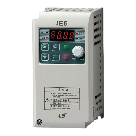
SV-iE5 User Manual
0.1~0.4kW (200V)
Read this manual carefully before
installing, wiring, operating, servicing
or inspecting this equipment.
Keep this manual within easy reach
for quick reference.
Advertisement
Table of Contents
Troubleshooting

Subscribe to Our Youtube Channel
Related Manuals for LS Industrial Systems SV-iE5


Summary of Contents for LS Industrial Systems SV-iE5
- Page 1 Right choice for ultimate yield LSIS strives to maximize customers' profit in gratitude of choosing us for your partner. SV-iE5 User Manual 0.1~0.4kW (200V) Read this manual carefully before installing, wiring, operating, servicing or inspecting this equipment. Keep this manual within easy reach...
- Page 2 After reading this manual, keep it handy for any user to quickly refer to Read this manual carefully to user SV-iE5 Series Inverter’s functions appropriately and safely. Warning Do not remove the cover while the power is applied or the unit is in operation.
- Page 3 Instructions Caution Install the inverter on a non-flammable surface. Or, it may cause a fire if being installed on or closely to a flammable material. Disconnect the input power if the inverter gets damaged. Or, it may result in a secondary accident and fire. After the input power is applied or removed, the inverter will remain hot for a couple of minutes.
- Page 4 Instructions (2) Wiring Do not connect a power factor correction capacitor, surge suppressor, or RFI filter to the output of the inverter. The connection orientation of the output cables should be in good order of U, V, W. Incorrect terminal wiring could result in the equipment damage. Reversing the polarity (+/-) of the terminals could damage the inverter.
- Page 5 Instructions (7) Disposal Dispose of the inverter as treating industrial waste. (8) General instructions Many of the diagrams and drawings in this instruction manual show the inverter without a circuit breaker, a cover or partially open. Never run the inverter like this. Always place the cover with circuit breakers and follow this instruction manual when operating the inverter.
- Page 6 The purpose of this manual is to provide the user with the necessary information to install, program, start up and maintain the SV-iE5 series inverter. To assure successful installation and operation of the SV-iE5 series inverter, the material presented must be thoroughly read and understood before proceeding This manual contains...
-
Page 7: Table Of Contents
Contents Contents 1. Basic Information & Precaution ..........................1-1 Important precautions ..........................1-1 Parts’ Names & Details ..........................1-2 Assembling & Disassembling........................1-3 Installation................................. 2-1 Installation precautions ..........................2-1 Dimensions..............................2-4 Wiring ..................................3-1 Control Terminal Wiring Diagram......................3-1 Power Terminal Wiring Diagram ....................... 3-1 Grounding Specification .......................... - Page 8 Contents V/F Control ...............................9-11 Stop method select..........................9-14 Frequency limit............................9-15 10. Advanced Functions ............................... 10-1 10.1 DC Brake..............................10-1 10.2 Jog operation............................10-3 10.3 UP – DOWN operation..........................10-4 10.4 3-Wire operation............................10-5 10.5 Dwell operation ............................10-5 10.6 Slip Compensation Control ........................
- Page 9 Contents 14.4 Inverter functional code setting....................... 14-3 14.5 Operation..............................14-4 14.6 COM Protocol(ModBus-RTU) ......................... 14-4 14.7 Communication Protocol (LS BUS) ......................14-5 14.8 Parameter code list ..........................14-9 14.9 Troubleshooting............................. 14-15 14.10 ASCII Code List............................. 14-16 15. Specifications ................................15-1 15.1 Technical data ............................
-
Page 10: Basic Information & Precaution
Chapter 1. Basic Information & Precaution 1. Basic Information & Precaution 1.1 Important precautions Unpacking & Unpack the package and check the inverter type, output ratings on the nameplate and Inspection whether the inverter is intact. In addition, inspect the inverter for any damage that may have occurred during shipping. -
Page 11: Parts' Names & Details
Chapter 1. Basic Information & Precaution 1.2 Parts’ Names & Details Appearance Variable resistance Status frequency setting display RUN button Front cover: Removed when wiring and Cover screws installing Inverter nameplate: Indicating the capacity and rating of the inverter Inside view with front cover removed Refer to 1.3 for details when remove front cover. -
Page 12: Assembling & Disassembling
Chapter 1. Basic Information & Precaution 1.3 Assembling & Disassembling To remove the front cover, press both indented sides of the cover lightly and pull it up. Remove the screw for wiring Press the indented sides to remove the cover. The front cover is completely removed if lifting it up and removing the fixed part. -
Page 13: Installation
Chapter 2. Installation 2. Installation 2.1 Installation precautions CAUTION Handle the inverter with care to prevent the plastic components damaged. Avoid installing the inverter in a place where vibration from bogie or press exists. Install in a location where ambient air temperature is within the permissible range (-10 ~ 40°C) Maximum Surrounding Air Temperature of 40 °C (UL508C) <... - Page 14 Chapter 2. Installation When two or more inverters are installed inside a panel, the inverters and fans must be installed in proper positions with extreme care. Install the inverter using screws or bolts to insure the inverter is firmly fastened. <...
- Page 15 Chapter 2. Installation Warning Follows procedure below when Install the inverter for successful operation. iE5 has self cooling structure using air. Therefore install the inverter vertically possible to air Caution circulation. Malfunction or fire may be caused when installed horizontally. Heat protection pin of iE5 is a high heating element.
-
Page 16: Dimensions
Chapter 2. Installation 2.2 Dimensions Inverter 001iE5-1 002iE5-1 004iE5-1 001iE5-2 002iE5-2 004iE5-2 φ Weight(kg) 0.44 0.46 0.68 0.43 0.45 0.67 Note Use M4 screw for fixing the inverter on a panel. -
Page 17: Wiring
Chapter 3. Wiring 3. Wiring 3.1 Control Terminal Wiring Diagram Description FX : forward run Multi RX : reverse run function EST : emergency stop Input RST : trip reset terminal JOG : jog operation 12V power(12V,100mA) for external volume Analogue frequency input(Voltage or current) Analogue output: 0 ~ 10V Input signal common... -
Page 18: Grounding Specification
Chapter 3. Wiring CAUTION Suitable For Use On A Circuit Capable of Delivering Not More Than 5000 RMS Symmetrical Amperes, 240 Volts Maximum. (UL508C) Use Copper Conductors Only, 75 °C only with a torque rating. (UL508C) Make sure the input power is off before wiring. When the inverter’s input power is cut off after operation, wire it after DC circuit voltage inside the inverter is fully discharged by measuring P1 and N with a tester (voltameter). -
Page 19: Control Terminal Wiring Specification
Chapter 3. Wiring 3.4 Control Terminal Wiring Specification Terminal description COM optional terminal AM CM Terminal description Wire size Torque [lb-in] Remarks P1~P5 Multi-function input T/M 1-5 22 AWG,0.3 mm Power T/M for external volume resistance 22 AWG,0.3 mm Analogue frequency input T/M 22 AWG,0.3 mm Multi-function output T/M 22 AWG,0.3 mm... -
Page 20: Pnp/Npn Modes Switch
Chapter 3. Wiring 3.5 PNP/NPN Modes Switch P1 P2 P3 P4 P5 Internal Power [NPN](up) Using internal P1 P2 P3 P4 P5 External power [PNP](down) Using external 24 Vdc Voltage input[ V ](right) Current input[ I ](left) Analogue Analogue voltage input current input 1) Using external current 2) Using external voltage... -
Page 21: Peripheral
Chapter 4. Peripheral 4. Peripheral 4.1 Configuration of Peripherals Correct peripherals must be selected and properly connected. An incorrectly applied or installed inverter may result in system malfunction or reduction in product life as well as component damage. You must read and understand this manual thoroughly before proceeding. -
Page 22: Recommended Mccb And Magnetic Contactor
Chapter 4. Peripheral 4.2 Recommended MCCB and Magnetic Contactor MCCB (LSIS) ELB (LSIS) MC (LSIS) Model 001iE5-1 GMC- 9 002iE5-1 GMC-12 004iE5-1 GMC-18 ABS33b EBS33b 001iE5-2 GMC- 9 002iE5-2 GMC- 9 004iE5-2 GMC-12 4.3 Recommended Reactors Model AC Input fuse AC reactor DC reactor 001iE5-1... -
Page 23: Loader
Chapter 5. Loader 5. Loader 5.1 Configuration FWD/REV LED SET LED RUN LED 7 Segment LED UP, DOWN SHFT FUNC RUN,STOP/RESET Volume Resistance Note STOP key of the inverter iE5 also contains reset function, which is used to cancel trip. Trip may be cancelled by using this key. -
Page 24: Alpha-Numeric View On The Led
Chapter 5. Loader 5.2 Alpha-numeric view on the LED Refer to the below table summarizing the characters displayed on the LED. Inverter LED Inverter LED Inverter LED Inverter LED Note Inverter iE5 uses 7-segment display. Therefore, it displays numbers and alphabet as the above table. Make sure to fully comprehend them for reading the fault messages/functional information. -
Page 25: Moving To Other Groups
Chapter 5. Loader 5.3 Moving to other groups There are two different parameter groups in SV-iE5 series as shown below. Drive group PG group Type Description Drive group Basic parameters necessary to operate the inverter; target frequency, acceleration/deceleration time and etc. -
Page 26: How To Move Among Codes In A Group
Chapter 5. Loader 5.4 How to move among codes in a group Moving between groups Moving from 15 of PG Group to Drive Group SHFT PG group Drive group -. Display Code 15 of PG Group. -. Press SHFT key. -. - Page 27 Chapter 5. Loader Code jump Moving from code 1(P 0) to the code15(P15) in PG Group -. It displays P0, the 1st code of Drive Group. -. Press FUNC key. F U N C -. SET lamp lights up. Changeable number blinks -.
- Page 28 Chapter 5. Loader Frequency setting When changing RUN frequency to 30.05 [Hz] in Drive Group FUNC SHFT FUNC Drive group -. It displays Target Frequency, the 1st code of Drive Group. -. Press FUNC key. -. SET lamp lights up. -.
-
Page 29: How To Set Parameters
Chapter 5. Loader 5.5 How to set parameters Parameter change in Drive Group Changing acceleration duration from 5.0 to 16.0 seconds FUNC FUNC Drive group SHFT SHFT -. It displays the target frequency, the 1st code of Drive Group. -. Press UP( ) key. -. - Page 30 Chapter 5. Loader Parameter change in PG Group Changing P34, Code 34 of PG Group from 0 to 1 F U N C F U N C S H F T F U N C S H F T F U N C PG group -.
-
Page 31: Monitoring Operation Status
Chapter 5. Loader 5.6 Monitoring Operation Status Displaying Current Output Monitoring output current in Drive Group FUNC FUNC Drive group -. The target frequency, Code 1 of Drive Group is displayed -. Press UP( ) key or DOWN( ) key until Cur is displayed. -. - Page 32 Chapter 5. Loader Fault display How to monitor fault condition in Drive Group Accel Overcurrent trip Current Frequency FUNC Drive group STOP -. OCt appears when an Overcurrent fault occurs. -. Press FUNC key. -. Press UP( ) key or DOWN ( ) key. -.
- Page 33 Chapter 5. Loader When types of faults occur at the same time When Overcurrent(OCt), overvoltage(Ovt) and overheat(OHt) occur simultaneously Overheating Overvoltage Overcurrent Drive -. When various trips occur simultaneously, it shows like the figure above and it can show up to 3 trips. Note In case inverter trip occurs, it shows the type in the current fault status indication code.
-
Page 34: Basic Operation
Chapter 6. Basic Operation 6. Basic Operation 6.1 Frequency Setting and Basic Operation Note The following parameters are set to factory defaults. Therefore, results may be different if any parameter is changed by a user. In this case, initialize parameters(see page 10-13) back to factory defaults and follow the instructions below. - Page 35 Chapter 6. Basic Operation If setting frequency with volume resistance on the loader and commanding operation on the inverter’s terminal Indication Operation & description -. Target frequency, the first code of Drive Group when turning it on. -. Press UP( ) key four times. -.
- Page 36 Chapter 6. Basic Operation If setting frq with volume resistance on the loader and commanding operation with RUN key on the loader Indication Operation & description -. Target frequency, the first code of Drive Group when turning it on. -. Press UP( ) key three times. -.
-
Page 37: Function List
Chapter 7. Function List 7. Function List Drive Group Adj. Min/Max Factory Display Name Description during Page range defaults Frequency 0 ~ 200 This parameter sets the operation frequency. 0.00 command [Hz] During stop, it displays Frequency Command; During run, it shows output frequency. During multi-step operation, it becomes frequency 0. - Page 38 Chapter 7. Function List Drive Group Adj. Min/Ma Factory Display Name Description during Page x range defaults Output current Display output current 11-1 No. of motor Display the no. of motor rotation(RPM) 11-1 rotation Inverter Display DC voltage inside the inverter 11-1 voltage Output voltage...
- Page 39 Chapter 7. Function List PG Group Adj. Min/Max Factory Display Name Description during Page range defaults Jump code 0 ~ 88 Sets the code number to jump Fault log 1 It logs the information on the types of 11-4 faults, and the frequency, current and status such as acceleration, deceleration and stop at the time of trouble.
- Page 40 Chapter 7. Function List PG Group Adj. Min/Max Factory Display Name Description during Page range defaults DC brake start 0 ~ 200 It sets the amount of DC voltage before a motor 10-2 voltage starts to run. Motor rated current(P43) DC brake start 0 ~ 60 It applies the current to a motor for the set time...
- Page 41 Chapter 7. Function List PG Group Adj. Min/Max Factory Display Name Description during Page range defaults Output 40 ~ 110 It adjusts the amount of output voltage, based on 9-12 voltage the percentage of input voltage. adjustment Overload trip 0 ~ 1 This parameter turns off the inverter output when 12-1 selection...
- Page 42 Chapter 7. Function List PG Group Adj. Min/Max Factory Display Name Description during Page range defaults Dwell 0.1 ~ 200 When run frequency is issued, motor starts to 5.00 10-5 frequency [Hz] accelerate after dwell frequency is applied to the motor during dwell time(P32).
- Page 43 Chapter 7. Function List PG Group Adj. Min/Max Factory Display Name Description during Page range defaults Speed 0 ~ 15 It is active to prevent any possible fault when 10-10 search [bit] the inverter outputs its voltage to the running selection motor.
- Page 44 Chapter 7. Function List PG Group Adj. Min/Max Factory Display Name Description during Page range defaults Number 0 ~ 10 It sets the number of restart tries after a 10-12 Auto Restart fault occurs. Auto Restart is deactivated if the fault outnumbers the restart tries. This function is active when [drv] is set to 1 or 2 {Run/Stop via control terminal}.
- Page 45 Chapter 7. Function List PG Group Adj. Min/Max Factory Display Name Description during Page range defaults Control mode 0 ~ 2 V/F control 9-11 selection Slip compensation control 10-6 PI control 10-8 P gain for PI 0~ 999.9 It sets the gains for the PI controller’s 300.00 controller response characteristics.
- Page 46 Chapter 7. Function List PG Group Adj. Min/Max Factory Display Name Description during Page range defaults Gain Motor 1 ~ 1000 It can monitoring on the rpm display code of 11-1 rpm display drive group as converting gear ratio of load system.
- Page 47 Chapter 7. Function List PG Group Adj. Min/Max Factory Display Name Description during Page range defaults Multi-function input 0 ~ 24 Forward run command (FX) terminal P1 define Reverse run command (RX) Multi-function input EST-Emergency Stop Trip terminal P2 define temporary output cut-off Multi-function input...
- Page 48 Chapter 7. Function List PG Group Adj. Min/Max Factory Display Name Description during Page range defaults Filtering time 1 ~ 20 If the value is set higher, the responsiveness of the constant for Multi- Input terminal is getting slower. function Input terminal Analog output item...
- Page 49 Chapter 7. Function List PG Group Adj. Min/Max Factory Display Name Description during Page range defaults Fault output 0 ~ 7 Func. Operation Operation Operation 11-10 select [bit] when setting when when the number trip other low voltage auto than trip occurs restart voltage trip...
- Page 50 Chapter 7. Function List PG Group Adj. Min/Max Factory Display Name Description during Page range defaults Parity/stop bit 0 ~ 3 Sets communication parity and stop bit. setting Parity bit Stop bit 1 Stop Bit 2 Stop Bit Odd Parity 1 Stop Bit Even Parity 1 Stop Bit...
-
Page 51: Control Block Diagram
Chapter 8. Control Block Diagram 8. Control Block Diagram 8.1 Control Flow Frequency setting Motor Accel / Decel PW M control Drive mode 8.2 Frequency Setting & Drive Mode Setting Frequency setting Loader Drive group Analog input Analog input scale filter PG group PG group... -
Page 52: Frequency Setting, Drive Acc./Dec. Setting And V/F Voltage Control
Chapter 8. Control Block Diagram 8.3 Frequency Setting, Drive Acc./Dec. Setting and V/F Voltage Control DC brake voltage & time PG group P9~P12 DC brake start frq. Operation command Accel/decel Accel/decel time Max frequency pattern Drive group PG group PG group Operation P6,P7 Stop... -
Page 53: Basic Functions
Using Loader’s volume resistance(run in case of Frq: 3) SV-iE5 series basically offer volume resistance on the inverter’s loader for frequency command. Through this volume resistance, it supplies 0~5 V and enables frequency setting. At the moment, voltage input is indicated as input value. - Page 54 Chapter 9. Basic Functions Frequency setting with the loader’s volume resistance(V0) Group Code Parameter Name Setting Range Initial Unit Drive Group Frequency Command Frequency setting mode 0 ~ 4 PG Group Filter time constant for V0 input 0 ~ 9999 V0 input Min voltage 0 ~ 100 Frequency corresponding to P61...
- Page 55 Chapter 9. Basic Functions Frequency setting using AI(analogue input) terminal Group Code Parameter Name Setting Range Initial Unit Drive Group Frequency Command Frequency setting mode 0 ~ 4 PG Group Input filter time constant for AI 0 ~ 9999 Min. input for AI(V/I) 0 ~ 100 Frequency corresponding to P56 0 ~ 200...
-
Page 56: Multi-Step Frequency Setting
Chapter 9. Basic Functions Analogue frequency command fixed Group Code Parameter Name Setting Range Initial Unit Drive Group Frequency setting mode 2 ~ 3 0 ~ 4 PG Group Multi-function input terminal P1 0 ~ 24 select Multi-function input terminal P5 select ... -
Page 57: Operating Command Setting Method
Chapter 9. Basic Functions If running by using multi-step high/low, it is possible to run from 0 to 3 step in 4 combinations as the below figure. Step 3 Step 2 Step 1 Step 0 Frequency Time Step 0 Step 1 Spee Step 2 Step 3... - Page 58 Chapter 9. Basic Functions Operating command via FX, RX terminal Group Code Parameter Name Setting Range Initial Unit Drive Group Drive mode 0 ~ 3 PG Group Multi-function input terminal P1 define 0 ~ 24 Multi-function input terminal P2 define 0 ~ 24 ...
- Page 59 Chapter 9. Basic Functions FX/RX Run Disable Group Code Parameter Name Setting Range Initial Unit Drive Group Direction of motor rotation select F, r PG Group Forward/Reverse run disable 0 ~ 2 Select the direction of motor rotation. 0: Forward and Reverse run enable ...
-
Page 60: Accel/Decel Time And Pattern Setting
Chapter 9. Basic Functions Restart after fault reset Group Code Parameter Name Setting Range Initial Unit Drive Group Drive mode 1, 2 0 ~ 3 PG Group Restart after fault reset selection 0 ~ 1 Set P35 code to 1 ... - Page 61 Chapter 9. Basic Functions Accel/Decel time is set based on max. frequency and 0Hz. For instance, if it is set max. frequency to 60Hz, Accel/Decel time to 5 sec, and run frequency to 30Hz, time to reach 30Hz would be 2.5 sec. Max.
- Page 62 Chapter 9. Basic Functions Note If the target frequency is less than 40% of the max. frequency as below figure, it may not realize a complete s- shape pattern run with the ending partially cut. Max. frequency Target frequency Time Frequency Accel/Decel Disable Group...
-
Page 63: V/F Control
Chapter 9. Basic Functions 9.5 V/F Control Linear V/F pattern operation Group Code Parameter Name Setting Range Initial Unit PG Group Base frequency 30 ~ 200 60.0 Start frequency 0.1 ~ 10 V/F pattern 0 ~ 1 Set P22 code to 0(linear) ... - Page 64 Chapter 9. Basic Functions Square V/F pattern Group Code Parameter Name Setting Range Initial Unit PG Group V/F pattern 0 ~ 1 Set P22 code to 1 This pattern maintains squared volts. Appropriate applications are fans, pumps, etc Voltage 100% Frequency...
- Page 65 Chapter 9. Basic Functions Manual torque boost Group Code Parameter Name Setting Range Initial Unit PG Group Torque boost select 0 ~ 1 0 ~ 15 Torque boost in forward direction Torque boost in reverse direction Set P19 code of PG Group to 0(manual torque boost). ...
-
Page 66: Stop Method Select
Chapter 9. Basic Functions 9.6 Stop method select Decel to stop Group Code Parameter Name Setting Range Initial Unit PG Group Stop mode select 0 ~ 2 Set P8 code of PG Group to 0. Motor decelerates to 0 Hz and stops during the setting time. Frequency Time Operation... -
Page 67: Frequency Limit
Chapter 9. Basic Functions 9.7 Frequency limit Frequency limit using Max Frequency and Start Frequency Group Code Parameter Name Setting Range Initial Unit PG Group Max frequency 0 ~ 200 60.0 Start frequency 0.1 ~ 10 Max Frequency: Every frequency except P17(base frequency) has upper limit of frequency parameter. Therefore, any frequency cannot be set above the max. -
Page 68: Advanced Functions
Chapter 10. Advanced Functions 10. Advanced Functions 10.1 DC Brake Stopping motor by DC brake Group Code Parameter Name Setting Range Initial Unit PG Group Stop mode select 0 ~ 2 DC brake start frequency 0 ~ 60 DC brake wait time 0 ~ 60 DC brake voltage 0 ~ 200... - Page 69 Chapter 10. Advanced Functions Starting DC brake Group Code Parameter Name Setting Range Initial Unit PG Group DC brake start voltage 0 ~ 200 DC brake start time 0 ~ 60 P13 : It sets the level as a percent of Motor rated current. ...
-
Page 70: Jog Operation
Chapter 10. Advanced Functions Voltage Operation command 10.2 Jog operation Group Code Parameter Name Setting Range Initial Unit PG Group Jog frequency 0 ~ 200 10.0 PG Group Multi-function input terminal P3 select 0 ~ 24 Set a desirable jog frequency in P15 of PG Group. ... -
Page 71: Up - Down Operation
Chapter 10. Advanced Functions 10.3 UP – DOWN operation Group Code Parameter Name Setting Range Initial Unit PG Group 0 ~ 24 Multi-function input terminal P1 select Multi-function input terminal P3 select Multi-function input terminal P4 select Multi-function input terminal P5 select ... -
Page 72: 3-Wire Operation
Chapter 10. Advanced Functions 10.4 3-Wire operation Group Code Parameter Name Setting Range Initial Unit PG Group 0 ~ 24 Multi-function Input terminal P1 select] Multi-function Input terminal P5 select Select a terminal from P1-P5 for use as 3-Wire operation. ... -
Page 73: Slip Compensation Control
Chapter 10. Advanced Functions × ⎛ ⎞ − ⎜ ⎟ ⎝ ⎠ where, = rated slip frequency = rated frequency = motor rated rpm = no. of motor poles i.e.) rated frequency: 60Hz, rated rpm: 1740rpm, No. of poles: 4 ×... - Page 74 Chapter 10. Advanced Functions P41 : Enter the pole number on the Motor nameplate. P42 : Enter the slip frequency in accordance with the following formula and motor nameplate. × ⎛ ⎞ − ⎜ ⎟ ⎝ ⎠ where, = rated slip frequency = rated frequency = motor rated rpm = motor pole number...
-
Page 75: Pi Control
Chapter 10. Advanced Functions 10.7 PI Control Group Code Parameter Name Setting Range Initial Unit PG Group 0 ~ 3 Control mode select P gain for PI controller 0 ~ 999.9 300.0 Differential time for PI controller(I gain) 0.1~ 32.0 Feed forward gain for PI controller 0 ~ 999.9 PI output frequency upper limit... - Page 76 Chapter 10. Advanced Functions PI Control block diagram Analog Analog input scale input filter group group P55, P56~ Ref. freq setting Loader Drive group Analog Analog PI output input filter input scale freq limit group group group Loader PI control P55, P56~ volume...
- Page 77 Chapter 10. Advanced Functions 10.8 Speed search operation Group Code Parameter Name Setting Range Initial Unit PG Group 0 ~ 15 Speed search select Speed search current level 80 ~ 200 0~20 Multi-function relay Used to avoid any possible fault when the inverter outputs the voltage during operation after the load is removed ...
- Page 78 Speed search operation is suitable for loads with high inertia. Stop the motor and restart when friction in the load is high. SV-iE5 series keeps normal operation when power is restored in 15msec for the use of its inverter rating if it operates within the rated output(0.1kW, 0.2kW and 0.4kW inverter types).
-
Page 79: Speed Search Operation
Chapter 10. Advanced Functions 10.9 Auto Restart Operation Group Code Parameter Name Setting Range Initial Unit PG Group 0 ~ 10 No. of auto restart try Auto restart time 0 ~ 60 Set the frequency of auto restart activated in P38. ... -
Page 80: Operation Sound Select (Carrier Frequency Change)
Chapter 10. Advanced Functions 10.10 Operation Sound Select (carrier frequency change) Group Code Parameter Name Setting Range Initial Unit PG Group 0 ~ 15 Carrier frequency select Set the operating sound of the inverter. Operating sound affects the following advantages/disadvantages. When setting carrier frequency Motor sound reduced high... - Page 81 Chapter 10. Advanced Functions Password register Group Code Parameter Name Setting Range Initial Unit PG Group 0 ~ FFFF Password register 0 ~ FFFF Parameter lock Register password for parameter lock (P87). Password should be hexadecimal (0 ~ 9, A, B, C, D, E, F). Caution Use the registered password to cancel parameter lock again after setting parameter lock of P86 using the registered password.
- Page 82 Chapter 10. Advanced Functions Parameter lock Group Code Parameter Name Setting Range Initial Unit PG Group 0 ~ FFFF Parameter lock 0 ~ FFFF Password register Parameter may be protected by using password. Parameter lock is realized by using the password registered in P86. Display Description -.
-
Page 83: Monitoring
Chapter 11. Monitoring 11. Monitoring 11.1 Operating Status Monitoring Output current Group Code Parameter Name Setting Range Initial Unit Drive Group Output current Inverter output current can be monitored in CUr code. Motor RPM Group Code Parameter Name Setting Range Initial Unit Drive Group... - Page 84 Chapter 11. Monitoring User display select Group Code Parameter Name Setting Range Initial Unit Drive Group Output voltage display It displays the current inverter output voltage. Power on display Group Code Parameter Name Range Default PG Group Power on display Frequency command(0.0) Accel time(ACC) Decel time(DEC)
-
Page 85: Monitoring I/O Terminal
Chapter 11. Monitoring 11.2 Monitoring I/O Terminal Input terminal status monitoring Group Code Parameter Name Setting Range Initial Unit PG Group Input terminal status display Current input terminal status (ON/OFF) can be monitored in P71. The following is displayed when P1, P3, P4 are ON and P5 is OFF. 11.3 Monitoring Fault Condition Monitoring Current Fault Status... - Page 86 Chapter 11. Monitoring Fault history monitoring Group Code Parameter Name Setting Range Initial Unit PG Group Fault history 1 Fault history 2 Fault history 3 Reset fault history 0 ~ 1 P 1 ~ P 3: Up to 3 faults information is stored. ...
-
Page 87: Analogue Output
Chapter 11. Monitoring 11.4 Analogue output Group Code Parameter Name Setting Range Initial Unit PG Group Analogue output item select 0 ~ 3 Analogue output level 10 ~ 200 adjustment Output item and the level from the AM terminal are selectable and adjustable. P73: The selected item will be output to Analog output terminal (AM). -
Page 88: Multi-Function Output Terminal And Relay
Chapter 11. Monitoring 11.5 Multi-function output terminal and Relay Parameter Group Code Range Default Name FDT-1 Group FDT-2 FDT-3 FDT-4 FDT-5 Inverter overload(IOL) Motor stall(STALL) Multi-function Over voltage trip(Ovt) output Low voltage trip(Lvt) terminal select Inverter overheat(OHt) Command loss During run During stop During constant run During speed searching... - Page 89 Chapter 11. Monitoring P78: When 17(Fault display) is selected in P77, Multi-function output relay will be activated with the value in P78. 0 : FDT-1 Check whether the output frequency matches the user-setting frequency. Active condition: Absolute value (preset frequency-output frequency)<= Frequency Detection Bandwidth/ 2 Group Code Parameter Name...
- Page 90 Chapter 11. Monitoring 2 : FDT-3 Activated when run frequency meets the following condition. Active condition: Absolute value (detected frequency - run frequency) <= detected frequency Bandwidth/2 Group Code Parameter Name Setting Range Initial Unit PG Group Detected frequency 0 ~ 200 30.0 Detected frequency bandwidth 10.0...
- Page 91 Chapter 11. Monitoring 4 : FDT-5 Activated as B contact contrast to FDT-4. Active condition Accel time: Run Frequency >= FDT Level Decel time: Run Frequency > (FDT Level – FDT Bandwidth/2) Group Code Parameter Name Setting Range Initial Unit PG Group Detected frequency 0 ~ 200...
- Page 92 Chapter 11. Monitoring 12 : During operation Activated when run command is input and inverter outputs its voltage. F requency R elay O peration com m and 13 : During stop Activated during stop without active command Frequency Relay Operation command 14 : During constant run Activated during constant speed operation...
-
Page 93: Protective Function
Chapter 12. Protective Function 12. Protective Function 12.1 Overload Trip Group Code Parameter Name Setting Range Initial Unit PG Group Overload trip select 0 ~ 1 Overload trip level 30 ~ 200 Overload trip time 0 ~ 60 Set P24 of PG Group to 1. ... -
Page 94: User's Fault Detection
Chapter 12. Protective Function For example, set P27 to 3 to make stall prevention active during Acceleration and constant run. When stall prevention is executed during acceleration or deceleration, Accel/Decel time may take longer than the user-setting time. When stall prevention is activated during constant run, t1, t2 executed in accordance with the value set in ACC - [Accel time] and dEC - [Decel time]. -
Page 95: External Trip Signal
Chapter 12. Protective Function Ground Ground Input Output Input Output fault fault phase phase phase phase Display during Display during loss loss loss loss operation operation [COL] [Pot] [COL] [Pot] [GCt] [GCt] 12.4 External trip signal Group Code Parameter Name Setting Range Initial... -
Page 96: Frequency Command Loss
Chapter 12. Protective Function 12.5 Frequency command loss Group Code Parameter Name Setting Range Initial Unit PG Group Criteria for analogue input signal 0 ~ 2 Drive mode select after loss of 0 ~ 2 frequency command Wait time after loss of frequency 0.1~120 command Multi-function relay select... -
Page 97: Inverter Overload
Chapter 12. Protective Function i.e.) when P65 is set to 2, P81 to 2, P82 to 5.0 sec and P77 to 11, respectively, Frequency input 5 sec Frequency Relay Operation command 12.6 Inverter overload Group Code Parameter Name Setting Range Initial Unit Multi-function output terminal... -
Page 98: Troubleshooting And Maintenance
Chapter 13. Troubleshooting and Maintenance 13. Troubleshooting and Maintenance 13.1 Protective Functions Caution When a fault occurs, the cause must be corrected before the fault can be cleared. If protective function keeps active, the inverter should restart after clearing the cause(s). Or, it may lead to reduction in product life and damage to the equipment. - Page 99 Chapter 13. Troubleshooting and Maintenance Protection of abnormal internal circuit and external signal Protective Fault display Description function Parameter Displayed when user-setting parameters fail to be entered into memory. save error Displayed when an error occurs in CPU operation and internal OS program. The Inverter fault may not be relieved simply by STOP/RST key of the loader or reset terminal.
-
Page 100: Fault Remedy
Chapter 13. Troubleshooting and Maintenance 13.2 Fault Remedy Caution If any trouble occurs due to overcurrent, make sure to restart after eliminating the causes because power semiconductor element inside the inverter may be broken. Protective function Cause Remedy Increase the Accel/Decel time. Accel/Decel time is too short compared to the inertia of the load(GD Load is greater than the inverter rating. - Page 101 Chapter 13. Troubleshooting and Maintenance Fault Remedy Protective function Cause Remedy Faulty contact of magnetic switch Make connection of magnetic switch at at output output of the inverter securely. Output Phase loss Check output wiring. Faulty output wiring Decel time is too short compared Increase the Decel time.
-
Page 102: Precautions For Maintenance
Chapter 13. Troubleshooting and Maintenance 13.3 Precautions for maintenance Warning Make sure to remove the input power while performing maintenance. Make sure to perform maintenance after checking the DC link capacitor has discharged. The bus capacitors in the inverter main circuit can still be charged even after the power is turned off. Check the voltage between terminal P or P1 and N using a tester before proceeding. -
Page 103: Com Option (Rs-485)
Introduction SV-iE5 inverter can be controlled and monitored by the sequence program of the PLC or other master module. Drives or other slave devices may be connected in a multi-drop fashion on the RS-485 network and may be monitored or controlled by a single PLC or PC. -
Page 104: Installation
Chapter 14. COM Option (RS-485) 14.3 Installation Connecting the communication line Connect(wire) to the inverter’s (S+), (S-) terminals of the control terminals as shown in the below figure. Use CM terminal on the lower control terminal for COM signal shield ground. COM dedicated terminal is delivered with iE5 COM optional product. -
Page 105: Inverter Functional Code Setting
Chapter 14. COM Option (RS-485) Cable Specification If communicating by using RS-422 or RS-485 channel, the twisted pair cable for RS-422 should be used considering the communication distance and speed. The specifications of the recommended cable are as follows. - Product : Low Capacitance Lan Interface Cable - Spec. -
Page 106: Operation
Chapter 14. COM Option (RS-485) Code Function Setting P 82 Determination time when speed command is lost 1.0 second P 83 COM waiting time Set the waiting time until the next TX signal output after receiving RX signal. P 84 Parity/STOP setting Set COM parity/stop bit P 89... -
Page 107: Communication Protocol (Ls Bus)
Chapter 14. COM Option (RS-485) 14.7 Communication Protocol (LS BUS) LS BUS protocol is dedicated communication protocol of LSIS. It is used for connecting of communication with LSIS PLC etc. Basic format Command message (Request): Drive No. Data 1 byte 2 bytes 1 byte n bytes... - Page 108 Chapter 14. COM Option (RS-485) Ex) Command Message (Request) for reading one address from address “3000” Number of Drive No Address address to read “01” “R” “3000” “1” “A7” 1 byte 2 bytes 1 byte 4 bytes 1 byte 2 bytes 1 byte SUM = ‘0’...
- Page 109 Chapter 14. COM Option (RS-485) 2) Request for Write: Number of Drive No Address Data address to read “01”~ “1F” “W” “XXXX” “1” ~ “8” = n “XXXX…” “XX” 1 byte 2 bytes 1 byte 4 bytes 1 byte n * 4 bytes 2 bytes 1 byte Total Byte = 12 + n * 4 = Max 44...
- Page 110 Chapter 14. COM Option (RS-485) 3.2) Negative Acknowledge Response: Drive No Error code “01” ~ “1F” “X” “**” “XX” 1 byte 2 bytes 1 byte 2 bytes 2 bytes 1 byte Total Byte = 9 4) Action Request for monitor register: Request for read of address registered by monitor register. Drive No “01”...
-
Page 111: Parameter Code List
8 : SV-iC5 2 : SV-iV 9 : SV-iP5 h0000 Inverter model 3 : SV-iH A : SV-iG5A 4 : SV-iS5 D : SV-iE5 5 :SV-iV5 h0001 Inverter capacity FFFF:100W 0000:200W 0001:200W h0002 Inverter Input Voltage - 0 : 220V class... - Page 112 Chapter 14. COM Option (RS-485) Address Parameter Scale Unit Data value h0009 Output Current See Function List. H000A Output Frequency 0.01 See Function List. H000B Output Voltage See Function List. H000C DC Link voltage See Function List. H000D Reserved BIT 0 : Stop BIT 1 : Forward running BIT 2 : Reverse running BIT 3 : Fault (Trip)
- Page 113 Chapter 14. COM Option (RS-485) Address Parameter Scale Unit Data value BIT 0 : P1 BIT 1 : P2 h0010 Input terminal status BIT 2 : P3 BIT 3 : P4 BIT 4 : P5 BIT 0 ~6: Not Used h0011 Output terminal status BIT 7 : 30AC...
- Page 114 Chapter 14. COM Option (RS-485) PROGRAM group Address Code Parameter Initial Max. Min. 16bit 10bit D201 53761 Last Fault1 D202 53762 Last Fault2 D203 53763 Last Fault3 D204 53764 Fault Clear D205 53765 Run Prohibit D206 53766 ACC Pattern D207 53767 DEC Pattern D208...
- Page 115 Chapter 14. COM Option (RS-485) Address Code Parameter Initial Max. Min. 16bit 10bit D221 53793 P 33 Trip select D222 53794 P 34 Power-on run D223 53795 P 35 RST restart D224 53796 P 36 Speed Search D225 53797 P 37 SS Sup-Curr D226 53798...
- Page 116 Chapter 14. COM Option (RS-485) Address Code Parameter Initial Max. Min. 16bit 10bit D243 53827 P 67 P2 define D244 53828 P 68 P3 define D245 53829 P 69 P4 define D246 53830 P 70 P5 define D247 53831 P 71 Input T/M status disp D248 53832...
-
Page 117: Troubleshooting
Chapter 14. COM Option (RS-485) 14.9 Troubleshooting Refer to Troubleshooting when RS -485 communication error occurs If communication is not connected Check points Corrective measures Is the power provided to the converter? Provide electric power to the converter. Are the connections between converter and computer Refer to converter manual. -
Page 118: Ascii Code List
Chapter 14. COM Option (RS-485) 14.10 ASCII Code List Character Character Character Character Character < > ₩ space " & 14-16... -
Page 119: Specifications
Chapter 15. Specifications 15. Specifications 15.1 Technical data Input & output ratings Type : SV xxx iE5 – x 001-1 002-1 004-1 001-2 002-2 004-2 [HP] Motor [kW] Capacity[kVA] 0.95 1.14 Current [A] Output ratings Output frequency 0 ~ 200 [Hz] Voltage [V] 3phase 200 ~ 230V Voltage [V]... - Page 120 Chapter 15. Specifications Operation Operation mode Select one of loader/terminal/COM operation(optional) Analogue: 0 ~ 10[V], 0 ~ 20[mA], loader volume Frequency setting Digital: loader Operation features PI, up-down, 3-wire NPN / PNP selectable(see page 3-5) Functions: FWD/REV RUN, Emergency stop, Fault reset, Jog operation, Multi-function terminal Multi-step Frequency-High &...
-
Page 121: Declaration Of Conformity
Units are certified for compliance with the following standards: EN 61800-3:2004 EN 50178:1997 Type of Equipment: Inverter (Power Conversion Equipment) Model Name: SV - iE5 Series Trade Mark: LS Industrial Systems Co., Ltd. Representative: LG International (Deutschland) GmbH Address: Lyoner Strasse 15, Frankfurt am Main, 60528, Germany Manufacturer: LG Industrial Systems Co., Ltd. - Page 122 TECHNICAL STANDARDS APPLIED The standards applied in order to comply with the essential requirements of the Directives 2006/95/CEE "Electrical material intended to be used with certain limits of voltage" and 2004/108/CEE "Electromagnetic Compatibility" are the following ones: • EN 50178 (1997) “Electronic equipment for use in power installations”.
- Page 123 EMI / RFI POWER LINE FILTERS LS inverters, iE5 series RFI FILTERS THE LS RANGE OF POWER LINE FILTERS FF ( Footprint ) - FE ( Standard ) SERIES, HAVE BEEN SPECIFICALLY DESIGNED WITH HIGH FREQUENCY LG INVERTERS. THE USE OF LS FILTERS, WITH THE INSTALLATION ADVICE OVERLEAF HELP TO ENSURE TROUBLE FREE USE ALONG SIDE SENSITIVE DEVICES AND COMPLIANCE TO CONDUCTED EMISSION AND IMMUNITY STANDARS TO EN 50081.
- Page 125 Tel. Note This product has been manufactured through the strict QC control and inspection of LS Industrial Systems. Warranty period is 12 months after installation or 18 months after manufactured when the installation date is unidentified. However, the guarantee term may vary on the sales term.
- Page 126 Manual Revision History Revision Changes Version. No Remarks Sept 2006 First edition 1.10 Jan 2007 Contents revised 1.10 Apr 2007 Contents revised 1.20 Jul 2008 Contents revised 1.30 Sustainable Management LS Industrial System Co.,Ltd take the highest priority on sustainable management and do our best to preserve the environment of the earth.
- Page 127 Tel: 86-532-580-2539 Fax: 86-532-583-3793 Tel: 86-411-8273-7777 Fax: 86-411-8730-7560 ※ LS Industrial Systems constantly endeavors to improve its product so that SV-iE5/2008.07 Information in this manual is subject to change without notice. ⓒ LS Industrial systems Co., Ltd 2006 All Rights Reserved.
Need help?
Do you have a question about the SV-iE5 and is the answer not in the manual?
Questions and answers
Not working