Table of Contents
Advertisement
Quick Links
This user manual describes all proceedings concerning the
operations of this CNC system in detail as much as possible. However, it is
impractical to give particular descriptions for all unnecessary or unallowable
system operations due to the manual text limit, product specific applications
and other causes. Therefore, the proceedings not indicated herein should
be considered impractical or unallowable.
This user manual is the property of GSK CNC Equipment Co., Ltd. All
rights are reserved. It is against the law for any organization or individual
to publish or reprint this manual without the express written permission of
GSK and the latter reserves the right to ascertain their legal liability.
Advertisement
Table of Contents

Related Manuals for GSK GSK983Ma


Summary of Contents for GSK GSK983Ma
- Page 1 Therefore, the proceedings not indicated herein should be considered impractical or unallowable. This user manual is the property of GSK CNC Equipment Co., Ltd. All rights are reserved. It is against the law for any organization or individual to publish or reprint this manual without the express written permission of GSK and the latter reserves the right to ascertain their legal liability.
- Page 2 GSK983Ma Milling Machine Center CNC System User Manual Preface Your Excellency, It’s our pleasure for your patronage and purchase of this GSK983Ma Milling machining center CNC system made by GSK CNC Equipment Co., Ltd. GSK983Ma User Manual divides into three...
- Page 3 Safty Caution Safty Caution ! Accident may occur by improper connection and operation!This system can only be operated by authorized and qualified personnel. Please carefully read this manual before using! Refer to user manual issued by the manufacturer carefully before installing, programming and operating this product, and the relative operation should be performed based upon the user manual strictly.
- Page 4 GSK983Ma Milling Machine Center CNC System User Manual Statement ● In this manual we have tried as much as possible to describe all the various matters. However, we cannot describe all the matters which must not be done, or which cannot be done, because there are so many possibilities.
- Page 5 Cautions Cautions ■ Transportation and storage ● Do not pile the carton more than six layers. ● Do not climb, stand or place the heavy on the carton. ● Do not drag or move the production using the cable connected with the production.
- Page 6 GSK983Ma Milling Machine Center CNC System User Manual Security Responsibility Security responsibility for manufacturer ——Manufacturer should be take responsibility for the danger of the motor and the accessories which have been eliminated and/ or controlled in design and in structure.
-
Page 7: Table Of Contents
List List Programming Programming ............................1 Chapter One General........................1 ............................... 1 ENERAL 1.2 C ....................1 AUTIONS FOR EADING THIS ANUAL Chapter Two Specification ........................3 Chapter Three Programming ......................13 3.1 W ........................13 HAT IS ROGRAMMING 3.2 P ........................... 13 ROGRAM TRUCTURE 3.2.1 Block ............................. - Page 8 GSK983Ma Milling Machine Center CNC System User Manual 3.5.10 Exact stop check (G09)......................52 3.5.11 Exact stop check (G60) and cutting mode (G64) ..............52 3.5.12 Coordinate system setting (G92).................... 52 ~ 3.5.13 Workpiece coordinate system (G54 G59) ................53 3.5.14 Workpiece coordinate system changes by the program command ........
- Page 9 List 3.10.2 Variable ............................ 146 3.10.2.1 The Description of the Variable................... 147 3.10.2.2 The Notation of the Variable ....................147 3.10.2.3 Undefined Variable......................147 3.10.2.4 The Display and Setting of the Variable Value ..............148 3.10.3 Type of the Variable........................ 148 3.10.3.1 Local Variable # 1~# 33.....................
- Page 10 GSK983Ma Milling Machine Center CNC System User Manual 3.11.3.4 Tool Skip Signal........................189 3.11.4 The Display and Input of the Tool Data................189 3.11.4.1 The Display and Modification of the Tool group Number........... 189 3.11.4.2 The display of tool life data during the execution of machine program ......190 3.11.4.3 Presetting of the Tool Life Counter..................
- Page 11 List 4.3.8 Manual Spindle Function ......................224 4.3.9 Manual Auxiliary Function ....................... 226 4.4 D NC U LCD C ....... 226 ISPLAY AND PERATION OF THE NIT WITH HARACTER ISPLAYER 4.4.1 State Display ..........................230 4.4.2 Key Input ............................ 232 4.4.3 Display of Program Number and Sequence Numbers............
- Page 12 GSK983Ma Milling Machine Center CNC System User Manual 4.4.34.1 Output of NC Parameter ......................275 4.4.34.2 Input of NC Parameter......................275 4.5 G ..........................276 RAPHIC UNCTION 4.5.1 Display Type of The Graphic....................276 4.5.2 Graphic Parameter Setting ...................... 276 4.5.3 The Meaning of Graphic Parameter ..................
-
Page 13: Programming
“System”), which is a medium and high grade manufactured goods with high speed, high accuracy, high stability, and high cost performance. It has been developed base on the stable and reliable and the market requirement and the updated technical development by the GSK CNC Equipment Company. - Page 14 GSK983Ma Milling Machine Center CNC System User Manual The specification of the operation panel, the capacity of the CNC machine, the machine programming and operation method of the character CNC machine are performed by referring the manual issued by the manufacturer.
-
Page 15: Chapter Two Specification
Chapter two Specification Chapter Two Specification Name Specification item Standard: 3 axes (X, Y and Z) (It can be set to the 4 axis or the 5 axis based on the order. The address of 4 is selected from A, B, C, U, V and W, the 4 axis is Controlled axes straight line axis or rotation one which is set by parameter;... - Page 16 GSK983Ma Milling Machine Center CNC System User Manual range of 0~200%, the unit of feedrate set by parameter can be modified into 0.01 mm/min, 0.001 mm/min or 0.001inch/min. Automatic The linear acceleration or deceleration mode can be used at the rapid...
- Page 17 Chapter two Specification upon the dry run which is determined by the parameter setting. Each axis can be separately forbidden the feed of the commanded axis, if any commanded axis is added an interlocking during movement, all of Interlocking the axes of machine may decelerate and then stops. The machine accelerates then starts as long as the interlocking releases.
-
Page 18: Manual
GSK983Ma Milling Machine Center CNC System User Manual When the power is turned on and when NC is at the controllable state, send this signal to the machine side; when the power is turned off or the Ready NC signal controllable unit is overheat, stop to send any signal to the machine side. - Page 19 Chapter two Specification (1) Ambient temperature Work temperature: 0℃~45℃ Storage and transportation temperature: -20℃~55℃ (2) Relative humidity ≤90% (condensing), ≤95% (40 ) ℃ (3) Vibration Ambient condition Work vibration<0.5G, Storage and transportation vibration<1G (4) Ambient temperature When the NC device is used at the high concentration circumstances, such as in the dust, cutting oil or the organic solvent, is important to touch the manufacturer.
- Page 20 GSK983Ma Milling Machine Center CNC System User Manual system 12-digit the current spindle speed voltage based upon the selected gear output) A/S4 digit number 1~4. The shift of gear is performed during strong circuit, and its (analog output) B consequent GRA or GRB signal outputs to the side of NC. The higher 2-digit of S4 or lower 2-digit number of NC program command is outputted in terms of the BCD code.
- Page 21 Chapter two Specification As for the stored stroke limit 1, the area other than the one of parameter Stored stroke limit setting is the forbidden area. As for the stored stroke limit 2, the internal or the external area specified with parameter or program is forbidden Stored stroke limit area.
- Page 22 GSK983Ma Milling Machine Center CNC System User Manual compensation C. After the standard tool is positioned at the fixed point, and then the tool to be measured is fixed at the same mechanical fixed position manually. Tool length The length offset value of this tool is input regarded as an offset as long...
- Page 23 Chapter two Specification interpolation does not move (this axis is treated as an imagination axis), the other 2 axes can be performed a sine curve interpolation. The circular compensation is In the arc interpolation, the radius value R instead of I, J and K is performed using directly specified a radius to simplify a program.
- Page 24 GSK983Ma Milling Machine Center CNC System User Manual The tool path specified in program can be scaled up or down with the Scaling range of 0.001~99.999. The pulse only uses a MPG which can be performed a tool movement MPG insertion overlapped with the automatical operation command in the case of the machining is consecutively performed.
-
Page 25: Chapter Three Programming
Chapter Three Programming Chapter Three Programming 3.1 What is Programming The CNC machine moves in terms of the compiled program. When the parts are machined in NC, the tool path and other machining conditions should be edited into this program, and this program is regarded as part program. -
Page 26: Block
GSK983Ma Milling Machine Center CNC System User Manual Main program Subprogram Command 1 Command 1 Command 2 Command 2 ┊ ┊ ┊ ┊ ┊ ┊ ┊ ┊ [Rotor program ┊ command] ┊ Command n ┊ Command n+1 ┊ ┊ ┊... - Page 27 Chapter Three Programming Name Address Meaning Program number : (ISO)/O(EIA) Program number Sequence Sequence number number Preparation Command motion mode (linear, circular arc etc.) function X、Y、Z Movement command of coordinate axis A、B、C、U、V、 Movement command of additional axis Coordinate word Arc radius I、J、K Coordinate of circular arc center Feed function...
-
Page 28: Input Format
GSK983Ma Milling Machine Center CNC System User Manual Note: CR(EIA) ,LF(ISO) 3.2.3 Input format Each program word is composed of a block which must be specified in terms of the following description. This input format of this system is a changeable block format, therefore, both the number of program word of a block and the character number of one program word which can be changed, in this case, it is very convenient for programming. -
Page 29: Decimal Point Programming
Chapter Three Programming X50 . 123 Three digits following with the decimal point Five digits before the decimal point is 00050. Leading zero is omitted G00 can not be omitted (G00 specifies a rapid feed) even if the leading zero is omitted. Note 3: When an address is specified twice at one block, in principle, the last command is enabled, and the alarm does not perform. -
Page 30: The Maximum Command Value
GSK983Ma Milling Machine Center CNC System User Manual Note 4: The numbers can be used with or without the decimal point X1000 Y23.7; Y22359; Note 5: If the value specified is less than the value of the least input increment, and this value is then omitted. -
Page 31: Program Number
Chapter Three Programming 0ms~99999999 Dwell ″ ″ ″ Sequence 1~9999 number ″ ″ ″ setting Times of 1~9999 ″ ″ ″ repeated Offset number D、H 0~184 ″ ″ ″ The 2 M.S.T 0~999 ″ ″ ″ function 3.2.6 Program number This controllable device can be stored several programs into the NC memory, the program number is added to each program to distinguish these programs. -
Page 32: Sequence Number
GSK983Ma Milling Machine Center CNC System User Manual may not call for the subprogram. In this case, the characters more than 4 digits are deleted. Deletion method: editing-> program lock open-> move the cursor to the program O-> insert the “EOB”->... -
Page 33: Dimension Word
Chapter Three Programming 3.3 Dimension Word The dimension word decides the movement of tool, which is composed some commands relative to the numerical value by the address of movement axis and the numerical value indicates the movement direction and quantity. They may vary from the absolute and increment modes. (See the Section 3.3.8) Dimension word address Meaning... -
Page 34: Setting Unit
GSK983Ma Milling Machine Center CNC System User Manual with the machine, the serious mess may occur in programming, which the relative explanations have been described in the EIA RS-267-A or ISO841. However, the following explanations should be noticed during programming:... -
Page 35: Folds Input Unit
Chapter Three Programming following groups can be adopted. The least input The least Input/output increment movement unit Input in mm, output in mm 0.001mm 0.001mm Input in inch, output in mm 0.0001inch 0.001mm Linear Input in mm, output in inch 0.001mm 0.0001inch axis... -
Page 36: The Maximum Stroke
GSK983Ma Milling Machine Center CNC System User Manual Note 1: The input unit is either 0.0001inch or 0.001mm in the latter explanations in the manual. Note 2: The display unit changes into 0.01mm or 0.01deg by setting the BIT 2 (MDL) of parameter 006. -
Page 37: Workpiece Coordinate System
Chapter Three Programming 3.3.6 Workpiece coordinate system Several workpieces have been installed in machine, which the installation positions of these workpieces are different; therefore, several workpiece coordinate systems should be applied. In this case, 6 coordinate systems set in the machine in advance which can be selected by the 6 G codes (G54 ~... -
Page 38: Reference (Position) Point
GSK983Ma Milling Machine Center CNC System User Manual Note: When using the coordinate system set by G54~G59, return to the 1 reference position after the power is turned on, a workpiece coordinate system can be automatically set by G54, so the automatic coordinate system need not to be set. -
Page 39: Feed Function (Ffunction )
Chapter Three Programming The above figure is carried out by the increment command program: G91 X-60.0 Y40.0; However, it is carried out by the absolute command program: G90 X40.0 Y70.0; In order to make a compatibility with other NC systems for the program, each address in block can not changed the G90/91 command method. -
Page 40: Cutting Feedrate
GSK983Ma Milling Machine Center CNC System User Manual The override control of rapid traverse rate can be carried out by the switch on the machine operator panel. (F0, 25%, 50%, 100%) F0 is determined by the parameter 113 (SPDFL), and its unit is not indicated by the percentage (%), instead of the mm/min or inch/mm. -
Page 41: Feedrate Decelerates To 1/10
Chapter Three Programming feed, and the error is calculated by spending the time for measuring the movement distance which is more than 500mm, where is followed with the NC steady state. Note 2: Up to 7 digits can be performed for the F code, if the inputted feedrate is more than the upper limit value, which will clamp at this value if the movement command is performed. -
Page 42: F1-Digit Feed
GSK983Ma Milling Machine Center CNC System User Manual Note 2: The synchronous feed must be performed with the spindle installed a position encoder. Note 3: It also can be used when the position encoder speed is up to 1r/min., the feedrate maybe irregular, which does not affect the machining. -
Page 43: Automatic Corner Modification
Chapter Three Programming the feedrate rotates, the bigger the acceleration/deceleration tome constant occurs, the bigger the corner error is. Note 1: The feedrate changes between the blocks of the specified different movement, as follows: The previous block Positioning Cutting feed Not move New block Positioning... - Page 44 GSK983Ma Milling Machine Center CNC System User Manual c. The offset should be performed within the machining corner d. The axis moves along with the offset surface. e. G41 and G42 command codes are not performed in the following blocks.
- Page 45 Chapter Three Programming (1°≤θP≤179°). Suppose that the θ and θP are equivalent, the estimation error less than 0.001° may occur. 2) Operation range After the corner is affirmed to an inner one, the feedrate is modified from the corner range from Le in the corner intersection block to another.
-
Page 46: The Change Of Inner Side Arc Cutting
GSK983Ma Milling Machine Center CNC System User Manual The feedrate is modified from a to b and c to do for the program of an arc. ② 3) Modification value The modification value is set by the parameter #334. 1≤AOVOR (each gear 1%) ≤100 (%) It is also enabled for the dry run and the F1-digit command. -
Page 47: Preparation Function (Gfunction )
Chapter Three Programming However, if R is much smaller than R , namely, R =0, the tool may stop then. Therefore, after the least deceleration rate is set, when R ≤AOVMDR, the actual feedrate is FX (AOVMDR). The MDR is determined by the parameter #333. 1≤AOVMDR (each gear 1%) ≤100, which is also used for F1-digit and the dry run. - Page 48 GSK983Ma Milling Machine Center CNC System User Manual Table 3.5.1 G codes G code Group Function Positioning (rapid traverse) Linear interpolation (feed) Circular interpolation CW (Clockwise) Circular interpolation CCW (Counterclockwise) Dwell Speed Sine curve control (Specify an imagination axis) Exact stop check...
- Page 49 Chapter Three Programming Workpiece coordinate system 3 selection Workpiece coordinate system 4 selection Workpiece coordinate system 5 selection Workpiece coordinate system 6 selection Single direction positioning Exact stop check mode Automatic corner modification valid Cutting mode Simply call the Marco command Marco command modal call Macro command modal call cancellation Coordinate rotation ON...
-
Page 50: Plain Selection (G17, G18, G19)
GSK983Ma Milling Machine Center CNC System User Manual Note 1: The G code with is a start G code of each group. Namely, when the power is turned on or the resetting key is controlled when the system parameter of G code is specified, the G codes are set up therefore. -
Page 51: Single Direction Positioning (G60)
Chapter Three Programming The program of Y axis in 9600mm/min G00G91 X25.0 Y-10.0 Note 1: The rapid traverse feedrate in G00 command is set for each axis by the machine tool manufacturer, therefore, it can not be specified by the a programming. In the positioning of G00, the tool speeds up from the start till to the preset speed, which may rapidly move thereafter till decelerate to the end, and the next block is performed after confirming the “appropriate position”... -
Page 52: Linear Interpolation (G01)
GSK983Ma Milling Machine Center CNC System User Manual Note 1: G60, which is a one-shot G code. Note 2: During canned cycle for drilling, no single direction positioning is effected in Z axis. Note 3: No single direction positioning is effected in an axis for which no overrun has been set by the parameter Note 4: When the move distance 0 is commanded, the single direction positioning is not performed. - Page 53 Chapter Three Programming axes function. G01α____β____γ____δ____F____; Wherein α, β, γ, δ= X, Y, Z, A, B, C, U, V or W. Note 1: The feedrate of each axis direction is as follows: G01ααββ F f; α Feedrate of α axis direction: Fα= ·f β...
-
Page 54: Circular Interpolation (G02, G03)
GSK983Ma Milling Machine Center CNC System User Manual 3.5.5 Circular Interpolation (G02, G03) 3.5.5.1 Circular interpolation without an additional axis The command below will move a tool along a circular arc. Arc in the X——Y plane R____ X____Y___ F____; I____J___ Arc in Z——X plane... - Page 55 Chapter Three Programming incremental value according to G90 or G91. For the incremental value, the distance of the end point which is viewed from the start point of the arc is specified. The arc center is specified by address I, J and K for the X, Y and Z axes, respectively. The numerical value following I, J or K, however, is a vector in which the arc center is seen from the start point, and is always specified as an incremental value irrespective of G90 and G91, as shown below.
-
Page 56: Arc Interpolation With Additional Axis
GSK983Ma Milling Machine Center CNC System User Manual a) Absolute programming G92 X200.0 Y40.0 Z0; (I) G90 G03 X140.0 Y100.0 I-60.0 F300.0; G02 X120.0 Y60.0 I-50.0; X200.0 Y40.0 Z0; (II) G90 G03 X140.0 Y100.0 R60.0 F300; G01 X120.0 Y60.0 R50.0;... -
Page 57: Sine Curve Interpolation
Chapter Three Programming and K. The arc interpolation is specified by R is valid. 3.5.6 Sine curve interpolation In the helical cutting command, the sine interpolation can be carried out when the arc interpolation does not move (this axis is virtual axis) by specifying an arc command axis. The specification of the virtual axis is as follows: G07α0;... -
Page 58: Thread Cutting (G33)
GSK983Ma Milling Machine Center CNC System User Manual interpolation. In N003 block, the X axis does not move, the machine is on the state of dwell when the interpolation ends. Note 1: Virtual axis is only valid to the automatic operation, but the manual. - Page 59 Chapter Three Programming N20 G90 G00 X100.0 Y… S45 M03; Z200.0 N22 G33 Z120.0 F5.0 M19; N24 G00 X105.0 Z200.0 M00; X100.0 M03; N27 G04 X2.0 N28 G33 Z120.0 F5.0 Explanations: N20, N21: Position the tool on the center of aperture, the spindle CW. N22: The first thread cutting is performed, and its pitch is determined by address F.
-
Page 60: Automatic Reference Position Return (Reference Position G27~G30)
GSK983Ma Milling Machine Center CNC System User Manual 3.5.8 Automatic reference position return (Reference position G27~G30) 3.5.8.1 Reference position return check (G27) The point fixed on a machining plane is referred to as a reference position, if the reference position return is performed manually, and the tool is then positioned at this point. -
Page 61: Return From The Reference Position Automatically (G29)
Chapter Three Programming specified by this command is registered into NC. The operations in G28 block are shown below: Firstly, all of the controllable axes can be positioned to the intermediate point at the rapid traverse rate. Then, return to the reference position from the intermediate point. If the machine does not locked in this case, the indicator of reference position may be lighted up. - Page 62 GSK983Ma Milling Machine Center CNC System User Manual α and β are movement commands which are specified by the absolute/increment values based on the state of G90/G91 In the increment command, the increment value corresponding to the intermediate point should be specified.
-
Page 63: Nd , 3 Rd And 4 Th Reference Position Return (G30
Chapter Three Programming Note: When the workpiece coordinate system is changed after the tool reaches the reference position through the intermediate point by the G29/G30 command, the intermediate point also shifts to a new coordinate system. If G29 is then commanded, the tool moves to the commanded position through the intermediate point which has been shifted to the new coordinate system. -
Page 64: Exact Stop Check (G09)
GSK983Ma Milling Machine Center CNC System User Manual G04P(t) ; Any of the methods can be used for dwell, after the previous block is performed, the dwell must be through the (t) ms time before the next block is performed. -
Page 65: Workpiece Coordinate System (G54~G59)
Chapter Three Programming (r,δ= A、B、C、U、V、W) This command builds a coordinate system, the original of coordinate system is offered from the appointed distance of the tool position. This is called workpiece coordinate system, once this system is set up, the following absolute commands should be referred to a value from this workpiece coordinate system. - Page 66 GSK983Ma Milling Machine Center CNC System User Manual G54………………… Workpiece coordinate system 1 G55………………… Workpiece coordinate system 2 G56………………… Workpiece coordinate system 3 G57………………… Workpiece coordinate system 4 G58………………… Workpiece coordinate system 5 G59………………… Workpiece coordinate system 6 Six coordinate systems can be set by distance (Workpiece point 0 offset values) of each axis from the reference position to its 0 point.
- Page 67 Chapter Three Programming In the state of G54, when tool is positioned at the (200, 160), G92 X10 Y100; specify the workpiece coordinate system 1 (X , Y ) is moved by vector A, and other workpiece coordinates are also offset the ˊ...
-
Page 68: Workpiece Coordinate System Changes By The Program Command
GSK983Ma Milling Machine Center CNC System User Manual Fig. 2 G57:Workpiece origin offset of workpiece coordinate system 4 G58:Workpiece origin offset of workpiece coordinate system 5 G59:Workpiece origin offset of workpiece coordinate system 6 The procedures of workpiece coordinate setting can be performed by the coordinate measurement function: (1) Move the cursor to the workpiece coordinate serial number to be changed. -
Page 69: Inch/Metric Conversion (G20, G21)
Chapter Three Programming G92 which the function of the reference position is automatically set the coordinate system. Note: If the workpiece coordinate system setting function is used, all of the parameters No.375~378, 440 are set to 0 when the metric input is performed, and all of the parameters No. 379~382, 441 are set to 0 when the inch input is performed. - Page 70 GSK983Ma Milling Machine Center CNC System User Manual The boundary is set by the parameter, and the specified boundary is called forbidden area. Usually, it is never changed after the manufactory is set. So, it is set at the maximum stroke of machine which is equivalent the soft limit.
- Page 71 Chapter Three Programming Some part of cutter or jig must be checked to enter the forbidden area, so, the calculations among the X Y Z I J K are different. Point a is set if check point A enters the forbidden area, it is same to the b. If the point A is regarded as tool nose check, and if the tool length varies for each tool which is set to the longest tool, the tool setting is also safe regardless of the modification.
-
Page 72: Skip Function (G31)
GSK983Ma Milling Machine Center CNC System User Manual sequence of coordinate value of the two points is set incorrectly. Note 9: G22______; and G23; should be commanded in a single block. Note 10: The additional axis can not be used the function of stored stroke limit 2. -
Page 73: Compensation Function
Chapter Three Programming Specify the feedrate of block (G31) by BIT 7 (SKPF) of parameter 306 is as follows: a) Specify the feedrate by F code (It is can be specified at the previous place or in G31 block) b) Set the feedrate by parameter No.342 (PSKPFL). The coordinate values when the skip signal is turned on can be used in a custom Macro because they are stored in the custom Macro system variable #5061~#5065, as follows: #5061………………………X axis coordinate value when the skip signal is ON. - Page 74 GSK983Ma Milling Machine Center CNC System User Manual Z___H___; or H___; The setting of offset value in offset memory is moved in positive or negative for the end position of movement command along with Z axis. This function can be used by setting the difference between the tool length assumed during programming and the actual tool length of the tool used into the offset memory, and the compensation can be carried out regardless of the program change.
- Page 75 Chapter Three Programming Specify G49 or H00 when the tool length compensation will be cancelled. Once the H00 or G49 is specified, it may cancel and position again by the H00 or G49 Note 1: When the Z axis address followed with the G49 is omitted, the Z axis may position again, it is necessary to notice that the Z axis address can not be ignored after the G49.
-
Page 76: Tool Position Offset (G45~G48)
GSK983Ma Milling Machine Center CNC System User Manual H01= -4.0 (Offset value) N1 G91 G00 X120.0 Y80.0 ;……………(1) N2 G43 Z-32.0 H01 ;……………(2) N3 G01 Z-21.0 F1000 ;……………(3) N4 G04 P2000 ;……………(4) N5 G00 Z21.0 ;……………(5) N6 X30.0 Y-50.0 ;……………(6)... - Page 77 Chapter Three Programming Increase an offset value Decrease an offset value Increase the offset value by twice Decrease the offset value by twice The G codes are one-shot code, which is only valid in the specified block. Once the compensations are specified by D or H, which remains unchanged until other compensations are selected.
- Page 78 GSK983Ma Milling Machine Center CNC System User Manual c) Motion command-12.34 offset value +5.67 d) Motion command-12.34 offset value -5.67 2) G46 code (Only reduce an offset value) Try to reverse the symbol of offset value in G45 code, and it is then same as the G46.
- Page 79 Chapter Three Programming 0. When the movement amount in absolute code (G90) is set to 0, any operations may not be performed. Offset value +12.34 (Offset number 01) NC code G91 G46 X0 D01; G91 D01; D01; Equivalent X12.34 X-12.34 X-12.34 X12.34;...
- Page 80 GSK983Ma Milling Machine Center CNC System User Manual D ; G01 G45 X ; ; G45 Y Note 3: When the offset amount is more than the movement command value, the actual tool movement direction becomes reverse to the programmed direction.
- Page 81 Chapter Three Programming Refer to the 6.22: Tool position offset in circular interpolation N1 G46 G00 X___Y___D___; N2 G45 G01 Y___F___; N3 G45 G03 X___Y___I___; N4 G01 X___; Refer to the 6.23: Program using a tool offset Cutter compensation...
- Page 82 GSK983Ma Milling Machine Center CNC System User Manual G91 G46 G00 X80.0 Y50.0 D01; G47 G01 X50.0 F120; Y40.0; G48 X40.0; Y-40.0; G45 X30.0; G45 G03 X30.0 Y30.0 J30.0; G45 G01 Y20.0; G46 X0;……… The offset value only moves along – X direction 10.
-
Page 83: Cutter Compensation (G40~G42)
Chapter Three Programming 3.6.3 Cutter compensation (G40~G42) 3.6.3.1 The function of cutter compensation The tool with a radius R machines a workpiece specified in the Fig. A, the corresponding tool center must be a B path of the radius R, in this case, tool removes a tool distance is called offset, calculate the distance of the tool path (offset) by the function of tool compensation, refer to the following figure. -
Page 84: Plane Selection And Vector
GSK983Ma Milling Machine Center CNC System User Manual code. It is calculated inside the control unit, and its direction is up-dated in accordance with the progress of the tool feed of each axis. This offset vector (it is called vector in the following description) generates from the control unit, so that the tool offset movement can be calculated, and the actual path of tool radius offset programmed path can be carried out. - Page 85 Chapter Three Programming G code Function Cutter compensation cancel Cutter compensation left Cutter compensation right The system enters the cutter compensation mode with G41 or G42 code. The system enters the cancel mode with G40 code. Refer to the procedure of offset in the following figure. Start the block , the offset cancel mode becomes offset mode (G41) in this block.
-
Page 86: Details Of Cutter Compensation C
GSK983Ma Milling Machine Center CNC System User Manual N2 G01 Y900.0 F150; N3 X450.0; N4 G03 X500.0 Y1150.0 I-600.0 J250.0; N5 G02 X900.0 I200.0 J150.0; N6 G03 X950.0 Y900.0 I250.0 J0; N7 G01 X1150.0; N8 Y550.0; N9 X700.0 Y650.0; N10 X250.0 Y550.0;... - Page 87 Chapter Three Programming “outer side.” (i) Machining around the inner side Linear Linear Thereafter, the following descriptions are indicated as below: S indicates the single block dwell point L indicates that the tool moves along a straight line C indicates that the tool moves along an arc Linear Circular arc (ii) When the tool moves around the outside of a corner at an obtuse angle (90°≤α≤180°), tool...
- Page 88 GSK983Ma Milling Machine Center CNC System User Manual (Linear to Circular) Type B: (Linear to Linear) The intersection point is an intersected point with the offset path which is calculated by the two consecutive blocks. (Linear to Circular) The intersection described above-mentioned which the offset path is carried out from r length by two blocks (iii) When an acute angle is performed (α<90°...
- Page 89 Chapter Three Programming Type A (Linear Linear) (Linear Circular) Type B (Linear Linear) (Linear Circular)
- Page 90 GSK983Ma Milling Machine Center CNC System User Manual Note: In the case of Type B, when tool moves around straight line at the inner side of the pointed angle is less than 1 degree, the compensation is performed based on the following figure.
- Page 91 Chapter Three Programming Circular to Linear Circular to Circular A narrow pointed angle moves within 1° from linear to linear, in this case, the offset vector becomes excess large. Reader should infer in the same procedure, in case of arc to straight line, straight line to arc...
- Page 92 GSK983Ma Milling Machine Center CNC System User Manual and arc to arc. (ii) Tool movement around the outside of a corner at an obtuse angle (90°≤α<180°) Linear to Linear Linear to Circular Circular to Linear Circular to Circular (iii) Tool movement around the outside of a corner at an acute angle...
- Page 93 Chapter Three Programming Linear to Circular Circular to Linear Circular to Circular When an end position for the arc is not on the arc...
- Page 94 GSK983Ma Milling Machine Center CNC System User Manual When a leading is programmed on arc, the arc center switched with an arc end which is treated as an imaginary arc. The imaginary circle is regarded an arc of tool compensation which is compensated as a vector.
- Page 95 Chapter Three Programming 1) G40 has been commanded. 2) Treat the D00 as a tool compensation number The arc G02 or G03 can not be specified when the offset cancel is performed. An alarm No.34 may generate if it is commanded, and the NC stops. When performing offset cancel, circular arc commands (G02 and G03) are not available.
- Page 96 GSK983Ma Milling Machine Center CNC System User Manual Circular to Linear (ii) Type B Linear to Linear Circular to Linear (c) An outer side angle around the acute of an angle (α<90°) (i) Type A Linear to Linear...
- Page 97 Chapter Three Programming Circular to Linear (ii) Type B Linear to Linear Circular to Linear In the occasion of type B, when tool moves an acute angle within 1° with straight line to straight line from outer side, the form of compensation is as follows: (4) Cutter compensation G code in offset mode The cutter compensation G codes (G41, G42) can be separately specified by offset mode, the movement direction to the previous block is set an offset vector forming a correct angel, which is...
- Page 98 GSK983Ma Milling Machine Center CNC System User Manual Suppose that the codes (G41, G42) are included in the arc command, which may not perform a correct arc. The compensation direction switch can be carried out by specifying cutter compensation G codes (G41, G42), refer to the Note 2 “Switch offset direction in offset mode”.
- Page 99 Chapter Three Programming Circular to Linear Circular to Circular Generally, there is no intersection on tool path after the offset is added: If the switch of G41 and G42 are performed and there is no intersection of offset path If there is no offset path intersection but G41 and G42 are shifted from blocks A to B, then the vector vertical to the programmed direction is set up with the start of block B.
- Page 100 GSK983Ma Milling Machine Center CNC System User Manual b) Linear to Circular c) Circular to Circular The tool center path length from cutter compensation is more than the circumferential: Usually, the above-mentioned matter may not occur, it is possible that only when G41 and G42...
- Page 101 Chapter Three Programming In the above occasion, tool center path does not move a circle instead of the arc of P1~P2. Refer to the description which the alarm is caused for the interference check. If the tool will move along the entire circumference, and then this circumference must be commanded separately. (5) Cancel the temporary offset, and perform the following commands in offset mode, then the “temporary offset cancel”...
- Page 102 GSK983Ma Milling Machine Center CNC System User Manual In the same offset mode, if the G92 (absolute 0 point programming) is specified; the offset vector must be cancelled temporarily, and then recovered automatically. In the case of, the offset cancel motion does not perform, tool directly moves to the point of specified offset cancel vector from intersection, and then the tool moves to the intersection when the offset mode is recovered.
- Page 103 Chapter Three Programming However, when the movement value is 0, the tool move of this block is same as the one which is specified more than one block without any tool movement Two or above blocks without any tool movement can not be specified consecutively, otherwise, the vector along with tool movement direction which may generate a length equals to an offset value and the direction is vertical to the previous block.
- Page 104 GSK983Ma Milling Machine Center CNC System User Manual The above-mentioned command is specified in the offset mode which becomes an example as G17, the same as other occasions. In this case, the direction of the vector from the end of the previous block is specified by the above command.
- Page 105 Chapter Three Programming (G41) N5 G01 G91 X10000; N6 G02 J-6000; N7 G40 G01 X5000; Y5000 I-100 J-100; In the above occasion, tool center path does not move along with the circumference, but moves along with an arc from P ~P The alarm caused by the interference check is related with the following matters.
- Page 106 GSK983Ma Milling Machine Center CNC System User Manual This movement lists in the N7 block, so, the feedrate equals to the specified speed in N7. If block N7 is G00 mode, the tool is then moved at the rapid traverse rate. The tool moves in the feedrate in the G01, G02 and G03 modes.
- Page 107 Chapter Three Programming c) Positive or negative offset value and tool center path If the offset value is negative (-), which equals to change the G41 and G42 in the program. Therefore, if the original tool center moves along the outer side of the workpiece, the current one then moves along the inner side, and vice versa.
- Page 108 GSK983Ma Milling Machine Center CNC System User Manual (ii) Machine a groove which is less than a tool radius The cutter compensation is enforced the tool center path to move in the negative direction, the overcutting may occur, therefore, the alarm No.41 may issue at the start of this block, and NC operation stops.
- Page 109 Chapter Three Programming In the above figure, when the N1 block is performed, N3 and N6 are also read into the buffer, and the correct cutter compensation has been completed based on their relationships as above-mentioned figure. And, if the N3 (Z axis movement command) is separated, refer to the following matters: N1 G91 G00 G41 X50000 Y50000 D1;...
- Page 110 GSK983Ma Milling Machine Center CNC System User Manual Read N2 and N3 into the buffer and compensate performs based on its relationships when the N1 block is performed. Interference check Tool overcutting is called interference. The inference check function checks for tool overcutting in advance.
- Page 111 Chapter Three Programming (G41) N5 G01 G91 X8000 Y2000 D01; N6 G02 X3200 Y-1600 I-2000 J-8000 D02; N7 G01 X2000 Y-5000; (The offset value corresponding to D01: =2000) (The offset value corresponding to D02: =6000) In the above example, the arc in block N6 is placed in the one quadrant. But, after cutter compensation, the arc is extended to the four quadrants.
- Page 112 GSK983Ma Milling Machine Center CNC System User Manual (b) If the interference occurs after the (a) is modified, the tool is then stopped due to an alarm. If the interference occurs at the last vector while the (a) is checking or only one pair of vectors at the beginning of the checking and the vectors interfere, the alarm No.41 is generated and the tool is...
- Page 113 Chapter Three Programming Tool is stopped due to the alarm No.41 issues even though the actual interference does not occur, the tool path direction after cutter compensation is different from that of the programmed path direction. (b) Groove which is less than the cutter compensation value Like (a), the direction of tool path is different from the one of the programmed path.
-
Page 114: Functions D And H
GSK983Ma Milling Machine Center CNC System User Manual between the blocks —— —— should be calculated again. V ′ However, since vector is not calculated any more, compensation is accurately performed from position (13) Interference from manual input The manual operation interference during the cutter compensation, refer to the item e (Note 1) of Section 4.3.4.3 for the Manual II... -
Page 115: Enter Offset Value From The Program (G10)
Chapter Three Programming 3.6.6 Enter offset value from the program (G10) Theo offset value is used for tool position offset, tool length compensation and cutter compensation, which can be specified by G10 in programming. The command format is as follows: G10 P p R r p: offset number r: offset value... - Page 116 GSK983Ma Milling Machine Center CNC System User Manual Note 1: In a single block, G51 must be specified in the mode of G40, and the G50 can be specified in offset mode, the G51 must be cancelled by G50 after the scaling is performed Note 2: The position display is a coordinate value after scaling.
-
Page 117: Coordinate System Rotation (G68, G69)
Chapter Three Programming If the movement amount from point A to D is increment, the D’ becomes an object point on the programmed path, and the conversion point D’ becomes point E, and the tool moves to the point E , because only Y axis is specified. -
Page 118: Format
GSK983Ma Milling Machine Center CNC System User Manual Center of rotation 3.6.8.1 Format G68 α___β___R___; α, β: Two axes are specified with G17, G18 and G19 in X, Y and Z. (G90/G91 is valid) R: Rotation angle (CCW is +, which is specified by absolute. And the increment value also can be commanded by the setting of BIT7 (ROTR) of parameter 633). - Page 119 Chapter Three Programming commands. The compensation is performed to a coordinate rotation for a command program, after the coordinate is rotated, the offset of the tool compensation, tool length compensation and tool position offset can be performed. The increment position before the absolute value is specified after the block of G68, which is regarded as no rotation center.
-
Page 120: Relationships With Other Functions
GSK983Ma Milling Machine Center CNC System User Manual X0 Y0 G17 G69; X25.0 Y25.0 R45.0; X50.0; Y25.0; (Correct program) X0 Y0 G17 G69; G68 X25.0 Y25.0 R45.0; G90 X50.0 Y0; Y2.0; 3.6.8.2 Relationships with other functions (1) In the cutter compensation C, G68 and G69 can be specified. The rotation plane must be consistent with the one of the cutter compensation C. - Page 121 Chapter Three Programming N8 Y-2000; N9 G50 G69; Note 1: The scaling is valid in rotation center. Note 2: Specify G68 in the mode of G51, the first position command block followed with G68 must be specified by G90 (the N4 has been shown in above example.) Note 3: Note that the scaling center must be specified by I, J and K, and the coordinate rotation center must be used the X, Y and Z.
- Page 122 GSK983Ma Milling Machine Center CNC System User Manual , if the coordinate rotation is added, then the scaling moves to E ’. (4) Manual insertion When the manual is inserted, the system differs depending on the scaling (with or without).
-
Page 123: Parameter
Chapter Three Programming ① A→D, only when the Y axis is increment, it moves to E using scaling, but if the coordinate rotation is added, it moves to E ’. A→D, because the XY is performed by the absolute command, and it moves to E , if the ②... -
Page 125: The Function Of Cycle Machining
Chapter Three Programming 3.7 The function of cycle machining 3.7.1 The function of the external operation The function signal of external operation should be sent out from NC to one side of machine, after the positioning of X___Y___ is executed, and one side of the machine can be performed some especial operations based on this signal, such as clamping, drilling, and then perform a cycle. - Page 126 GSK983Ma Milling Machine Center CNC System User Manual 1. Positioning of axes X and Y 2. Rapid traverse up to point R level Operations 3. Drilling 4. Operation at the bottom of a hole 5. Retraction to point R level 6.
- Page 127 Chapter Three Programming Fig. 7.2.2 Absolute or increment programming (B) The return operation is performed, the tool is returned to the point R plane or the initial level plane which is determined by the specification of G98 or G99. Refer to the Fig. 7.2.3. Fig.
- Page 128 GSK983Ma Milling Machine Center CNC System User Manual Hole machining mode: G□□ (Refer to the table 7.2) Hole position data X, Y; A hole position can be specified by an absolute or increment. The selection of tool path and feedrate is performed either based on G code of group 01 or in terms of the G00 unconditionally, which is determined by BIT3 (FCUT) of parameter 9.
- Page 129 Chapter Three Programming Z………………… is specified in the block ⑦ R………………… is specified in the block ⑥ F………………… is specified in the block ② ⑨G01 X___Y___; In this case, the hole machining mode and hole machining data (other than the F) are cancelled. The description of each machining mode is shown below: (1) G73 (High speed peck drilling)
- Page 130 GSK983Ma Milling Machine Center CNC System User Manual Rapid traverse Cutting feed...
- Page 131 Chapter Three Programming Clearance “d” value is set by the parameter 067 (CYCR). The drilling can be performed with high-efficiency by the intermediate feed of the Z axis, and the cutting is easy to move. The retraction is carried out by the rapid traverse rate. (2) G74 (Left-handed tapping cycle) Rapid traverse Cutting feed...
- Page 132 GSK983Ma Milling Machine Center CNC System User Manual Dwell OSS spindle orientation stop (Spindle stops at the fixed point) Tool movement Rapid traverse Cutting feed Note: G76 can be correctly performed only when the parameter 009 BIT7 (FIX2) setting is outputted the M code, which is regarded as the output signal of the spindle negative, positive and spindle exact-stop.
- Page 133 Chapter Three Programming Rapid traverse Cutting feed (6) G82 (Drilling cycle, boring)
- Page 134 GSK983Ma Milling Machine Center CNC System User Manual Rapid traverse Cutting feed Dwell This command is same with the G81 (the dwell time is specified by address P) other than the retraction is performed after the dwell is executed at the bottom of the hole.
- Page 135 Chapter Three Programming (7) G83 (Peck drilling cycle) Rapid traverse Cutting feed the cutting depth for each time Q represents the depth of cut for each cutting feed. It must always be specified as an incremental value. The Q value is specified by the positive number, if it uses a negative number, the negative sign is then omitted.
- Page 136 GSK983Ma Milling Machine Center CNC System User Manual Rapid feed Cutting feed This command is specified that the spindle rotates CCW at the bottom of the hole, and performs a tapping cycle. Note: During the tapping is specified by G84, the stop (feed hold) can not be performed regardless of the feedrate till the cycle is executed, and it is not be affected even the feed hold occurs at this time.
- Page 137 Chapter Three Programming This command is same with the G84 other than the spindle is not reverse at the bottom of the hole. (10) G86 (Boring cycle)
- Page 138 GSK983Ma Milling Machine Center CNC System User Manual This command is same with the G81 other than the stop is performed at the bottom of the hole, and it can be returned at the rapid traverse rate. (11) G87 (Boring cycle/ Counter boring cycle)
- Page 139 Chapter Three Programming Cann cycle Not used Cann cycle Rapid traverse Cutting feed Manual feed Tool offset Spindle exact-stop Canned cycle I (Boring cycle) When the tool has been reached at the bottom of the hole and spindle is stopped, the control system is then entered to the hold state;...
- Page 140 GSK983Ma Milling Machine Center CNC System User Manual Canned cycle II (Counter boring cycle) The spindle orientation stop is performed after the X and Y axes are positioned. The tool is offset and positioned to the bottom of the hole (Point R) at the rapid traverse rate in the direction of the reverse tool nose.
- Page 141 Chapter Three Programming Rapid traverse Cutting feed The move path is same with the G85, but it dwell must be performed at the bottom of the hole.
-
Page 142: The Repetition Of The Canned Cycle
GSK983Ma Milling Machine Center CNC System User Manual 3.7.2.1 the repetition of the canned cycle The equispaced holes are repeatedly machined using the same canned cycle, which is specified the times of the repetition by the address L, the maximum value of the L is 9999, and the L is only effective in the existent block. - Page 143 Chapter Three Programming F— ;...
- Page 144 GSK983Ma Milling Machine Center CNC System User Manual of the feedhold is ON immediately, and the control equipment is stopped after continuously performing the operation 6. The operation is immediately stopped if the feed is enabled during operation 6. (d) Feedrate override The feedrate is fixed on the 100% during the canned cycle G74 or G84.
- Page 145 Chapter Three Programming For example, in the Section 7.2.2, the programming of the tool length compensation and canned cycle are used.
- Page 146 GSK983Ma Milling Machine Center CNC System User Manual Programming examples: N001 G92 X0 Y0 Z0; Setting the coordinate system at the reference position N002 G90 G00 Z250.0 T11 M06; Changing the No.11 tool N003 G43 Z0 H11; Initial point & tool length compensation N004 S300 M03;...
-
Page 147: The Initial Point And Point R In The Canned Cycle (G98, G99)
Chapter Three Programming N007 G98 Y-750.0; Drilling the 3# hole after positioning, then return to point R N008 G99 X1200.0; Drilling the 4# hole after positioning, then return to point R N009 Y-550.0; Drilling the 5# hole after positioning, then return to point R N010 G98 Y-350.0;... -
Page 148: Rigid Tapping Cycle (G180, G184)
GSK983Ma Milling Machine Center CNC System User Manual Fig. Initial position and point R 3.7.4 Rigid tapping cycle (G180, G184) 3.7.4.1 Brief The rotation of the spindle and the feedrate of the Z axis are separately controlled in the general... - Page 149 Chapter Three Programming Tool move path at the rapid traverse rate Tool move path at the cutting feedrate of the program Fig. 3.7.4...
-
Page 150: Explanation
The hole machining data, such as Z, R, Q, S, F and M3/M4 can not be changed in the rigid tapping cycle. g). It is recommended that the top tapping speed is within 1000r/min when matching the GSK DAP03 servo spindle. -
Page 151: Spindle Function (S Function), Tool Function (T Function), Miscellaneous Function (M Function), The
Chapter Three Programming Thread leading 1.0mm Note: The programming both the feed/min. and the feed/rev. are absolutely same. G00 G90 X120.0 Y100.0; Position G98 G184 Z-100.0 R-20.0 F1.0 Q1.0 M3 S1000; Rigid tapping X0; The rigid tapping is performed after the X is positioned to the X0. Y0;... -
Page 152: Spindle Function (S Function)
GSK983Ma Milling Machine Center CNC System User Manual Generally, it is determined by the machine builder to use which one method, the CNC machine builder can offer the abovementioned two methods. Refer to the manual issued by the manufacturer. 3.8.1 Spindle function (S function) 3.8.1.1 S2 digit... -
Page 153: Spindle Speed Rate
Chapter Three Programming that the coordinates of the rotation axis center is 0 (the axis is controlled by the constant surface speed). The constant surface control axis can be selected by the programming command. G96P ——; P1……………………The constant surface speed control specifies to X axis. P2……………………The constant surface speed control specifies to Y axis. -
Page 154: Tool Function (T Function)
GSK983Ma Milling Machine Center CNC System User Manual length compensation (G43 or G44) is performed in the front; if the tool position offset (G45~G48) is performed, the surface constant speed control is then computed by the current value. Note 8: The coordinate value change of the axis using the constant speed control is calculated by the surface constant speed control in the case of the machine lock. -
Page 155: The 2Nd Miscellaneous Function (B Function)
Chapter Three Programming 3.8.5 The 2nd Miscellaneous Function (B function) The working-table indexing can be appointed by the address B and the followed 3 digits. Different manufacturers have different specifications for the indexing value corresponded with the B code. 3.9 Sub-program Some fixed sequence or the repetition area are include in the block, which can be regarded as sub-program to store the memory, so that the programming can be simplified. -
Page 156: The Performance Of The Sub-Program
GSK983Ma Milling Machine Center CNC System User Manual 3.9.2 The Performance of the Sub-program The sub-program is performed when it is called by the main program or other sub-programs. Using the following format calling the sub-program: M98 P— — — —... - Page 157 Chapter Three Programming 3.9.3.2 If the M99 is performed in the main program, the control is then return to the beginning of the main program. For example, insert a “/M99;” block at a appropriate position of the main program, and turn off the optional block skip function, in this case, the control can be returned to the beginning of the main program, and this main program is performed again.
-
Page 158: User Macro Program
GSK983Ma Milling Machine Center CNC System User Manual 3.10 User Macro Program 3.10.1 General Brief The functions of the user macro program between A and B are mainly same, and the differences are described in the 3.10.10 (9). A certain group command composes of a certain function, and it is stored into the memorizer as the sub-program, these stored functions can be indicated by a command, so, the performed function is only specified the representative command. -
Page 159: The Description Of The Variable
Chapter Three Programming Each variable number is distinguished from the variable when some variable is used. 3.10.2.1 The Description of the Variable For example, a variable is composed of the variable notation (#) and its following variable number, which shown in the Section 10.2.1. #1(i=1,2,3,4……)... -
Page 160: The Display And Setting Of The Variable Value
GSK983Ma Milling Machine Center CNC System User Manual When an undefined variable is quoted, the address can be ignored. When #1=<Vacant> When #1=0 G90 X100 Y#1 G90 X100 Y#1 ↓ G90 X100 G90 X100 Y0 (2)Calculation formula It is same as the variable value other than the <Vacant> is regarded as the replacement. -
Page 161: Local Variable # 1~# 33
Chapter Three Programming 3.10.3.1 Local Variable # 1~# 33 The local variable is a used variable with local in the Marco program. In a certain moment, the local variable # i (i=1~33) is different (regardless of its same or not of the Macro program) for calling the Macro program and another one for calling the Macro program in another moment. - Page 162 GSK983Ma Milling Machine Center CNC System User Manual The reading of the variable value is 1.0 or 0.0 regardless of the unit, but the unit may not consider in the Macro program. The whole input signals are read once by reading the system variable #1032.
- Page 163 Chapter Three Programming Note 3: The connection of the user Macro program output signal is shown below: [For example 10.3.1] 1. Three-digit BCD data with the notation is read to the #100 by changing the address. The consist of the D1: Other purpose notation...
- Page 164 GSK983Ma Milling Machine Center CNC System User Manual Do not use Other purpose Address Macro program call command: G65 P9100 D (Address); The noumenon of the Macro program are described below: 09100; #1132=#1132 AND 496 OR #7; : Address sending G65 P9101 T60;...
- Page 165 Chapter Three Programming External workpiece offset #2600 #2601 ┆ ┆ #2606 External workpiece offset #2700 #2701 ┆ ┆ #2706 External workpiece offset #2800 #2801 ┆ ┆ #2806 External workpiece offset #2900 #2901 ┆ ┆ #2906 For example, refer to the #30=#2005 in the Section 10.3.2. The tool offset value of the tool number is substituted into the variable #30.
- Page 166 GSK983Ma Milling Machine Center CNC System User Manual Miscellaneous function end #3003 Single block stop signal Without forbiddance Waiting Forbiddance Waiting Without forbiddance Without waiting Forbiddance Without waiting For example: 10.3.4 Drill cycle (The incremental program) Macro program calling command G65 P9081L (Times of the repeat) R (point R) Z (point Z);...
- Page 167 Chapter Three Programming M05; M03; G00Z-#18; #3003=0; M99; Note: “M05” can be ignored as for some machines. (7) It is corresponding to the variable of the setting data #3005. The setting data can be set by evaluating the system variable #3005. Each digit corresponds with each setting data when the value of the system variable #3005 is expressed by the binary number.
- Page 168 GSK983Ma Milling Machine Center CNC System User Manual System Group of the Modal information variable G code G00、G01、G02、G03、G33 #4001 Group 01 G17、G18、G19 #4002 Group 02 G90、G91 #4003 Group 03 G22、G23 #4004 Group 04 G94、G95 #4005 Group 05 G20、G21 #4006 Group 06 G40、G41、G42...
- Page 169 Chapter Three Programming Read during System variable Position information the move #5001 X axis block end position (ABSIO) #5002 Y axis block end position (ABSIO) #5003 Z axis block end position (ABSIO) Possible #5004 The 4 axis block end position (ABSIO) #5005 The 5 axis block end position (ABSIO)
-
Page 170: Operation Command
GSK983Ma Milling Machine Center CNC System User Manual X#24 Y#25; G04; It is stopped due to reading the #5021~#5023. G91 X[XP-#5021]Y[yp-#5022]Z[ZP-#5023]; ┆ (Treatment) X#24 Y#25 Z#26; X#1 Y#2; Z#3; M99; (10) Setting and Display of the variable name The name composed by 8 character at most is assigned the #500~#511 variable by the following commands. -
Page 171: The Define And Replacement Of The Variable
Chapter Three Programming 3.10.4.1 the Define and Replacement of the Variable #i=#j Define, replacement 3.10.4.2 The Add Operation #i=#j + #k Summation #i=#j - #k Subtraction #i=#j OR #k Logical sum (Each digit of the 32 digits) #i=#j XOR #K Exclusive OR (Each digit of the 32 digits) 3.10.4.3 Multiply Operation (The selection of the Macro B) #i=#j * #k Product... -
Page 172: Compound Operation
GSK983Ma Milling Machine Center CNC System User Manual 3.10.4.5 Compound Operation The abovementioned operation and function can be combined. The priority sequence of the operation is function, multiply operation and add operation. For example #i= #j+#K*SIN[# ○ —— 1 ——Operation sequence ○... -
Page 173: Some Cautions For Reducing The Accuracy
Chapter Three Programming Note: Function TAN performs SIN/COS. 3.10.4.8 Some Cautions for reducing the accuracy (1)Add and Subtraction operation When the absolute is subtracted in add or subtraction, it is note that the relative error may not hold below the 10 . -
Page 174: Repeat The While (Macro Program B)
GSK983Ma Milling Machine Center CNC System User Manual command, and the sequence number n must be written at the beginning of this block. Note 2: The further the Nn block along with the direction is, the longer of the performance time is, when the GOTOn is executed. - Page 175 Chapter Three Programming Repeat for 10 times N2 WHILE [ #30EQ1 ] DO2; It is repeated when #30=1 N3 END 2; #120=#120+1; N4 END1; Note 1: It is very necessary to note the following items when the WHILE is programmed repeatedly. DOm should be specified before the ENDm.
- Page 176 GSK983Ma Milling Machine Center CNC System User Manual The area of the DO can not be intersected ⑤ ┆ DO1; ┆ DO2; ┆ END1; ┆ END2; ┆ It can be transferred from the internal of the DO area to the external.
-
Page 177: The Compilation Of The User Macro Program Body And Memory
Chapter Three Programming ┆ Note 2: Generally, the performance time of the repeat is short when the transfer and the repeated programming are used. For example: Waiting for the cycle program of one certain signal (#1000) is 1 ┆ N 10 I F[#1000 EQ 0]GOTO 10; ┆... -
Page 178: The Memory Of The User Macro Program Body
GSK983Ma Milling Machine Center CNC System User Manual 3.10.6.2 The Memory of the User Macro Program Body That one Macro program body is a kind of sub-program, which is used the same method with the sub-program to store and compile it. The store capacity is specified together with the sub-program. - Page 179 Chapter Three Programming Macro program statement N2 N3 NC statement performance Time (ii) The method of the cutter compensation C (2-1) The first NC statement is not the movement block (the block without movement command inside the cutter compensation plane) after the current performed block. (2-1-1) The 2 NC statement also is not the block without movement.
-
Page 180: Macro Call Command
GSK983Ma Milling Machine Center CNC System User Manual N4 Z1000; The 1 NC statement (block without movement) N5 #1101=1;The Macro program statement has been performed. N6 #2=20; The Macro program statement has been performed. N7 X-1000; The 2 NC statement... - Page 181 Chapter Three Programming (2) Argument designation II I J K I J K The argument, more than 10-group arguments can be specified by the address I, J, and K at most, other than assign the value to the address A, B and C. Several numbers should be assigned in sequence when they are assigned to the same address, and the unnecessary address can be omitted.
- Page 182 GSK983Ma Milling Machine Center CNC System User Manual The address of the The variable in the Macro argument designation II program body Subscripts 1~10 of the I, J and K are indicated the sequence being assigned group. (3) The argument designation I AND II are existed simultaneously.
- Page 183 Chapter Three Programming For example: The setting of the base point The base point of this hole group should be set before machining the hole group. The X coordinate value of the X hole group base point The Y coordinate value of the Y hole group base point The Macro program call command: G 65 P9200 X...
- Page 184 GSK983Ma Milling Machine Center CNC System User Manual The memory of the base point along with the X coordinate value The memory of the base point along with the Y coordinate value The counter indicates that the 1 hole is machined.
-
Page 186: Multiple Call
GSK983Ma Milling Machine Center CNC System User Manual G66 P9082 R(Point R)Z(Point Z)X(Dwell time) ; ; ; Some move block is carried out the drilling cycle in this area. ┋ G67 ; The Macro program is shown below (Incremental program): G9082;... -
Page 187: Macro Program Call By G Code
Chapter Three Programming successively by the following specified command. For example: 10.7.6 G66 P9100; Z10000; (1-1) G66 P9200; Z15000; (1-2) G67; :P9200 Cancel G67; :P9100 Cancel Z-25000; (1-3) 09100; X5000; (2-1) M99; 09200; Z6000; (3-1) Z7000; (3-2) M99; Performance sequence (The block without movement command is omitted.) (1-1)... -
Page 188: Call The Sub-Program By M Code
GSK983Ma Milling Machine Center CNC System User Manual (2) Editing the following Macro program body 09010; #1=ABS[#4]-#[2000+#7]; IF[#1 LE0]GOTO 1; #2=#1/2; #3003=3; G01 X[#1-ROUND[#2]]Y#2; G17 G02 X#2 Y-#2R-#2; I-#1; X-#2 Y-#2 R#2; G01 X[#-ROUND[#2]]Y#2]; #3003=0; N1 M99; 3.10.7.6 Call the Sub-program by M Code The M code set by the parameter can be used to call the sub-program. -
Page 189: Call The Macro Program By M Code
Chapter Three Programming 3.10.7.7 Call the Macro Program by M Code The M code set by the parameter can be called the Macro program. That is: N—G65 <The specification of the variable> △△△△ The operations are same replaced by the following commands. N—M××<The specification of the variable>... -
Page 190: M98 (Sub-Program Call) And G65 (Calling The Different Between The Macro Program Bodies)
GSK983Ma Milling Machine Center CNC System User Manual The numerical value abovementioned is the position of the decimal point calculating from the lowest effective digit. The numerical value in the ( ) is the digit at the right of the decimal point, address E, F in the BIT3 FMIC of the parameter 006 is equal to 1, and other address in the BIT1 MIC of the parameter 006 is equal to 1. -
Page 191: The Relationships With Other Functions
Chapter Three Programming 3.10.8 The Relationships with Other Functions (1) MDI operation Macro call instruction, operation instruction and control instruction cannot be specified with MDI. During the execution of a macro and the stop of a single block, the MDI instructions other than those are related to macros may be executed. -
Page 192: Special Codes And Words Used In User Programs
GSK983Ma Milling Machine Center CNC System User Manual MPD8 = 1 corresponds to the user macros and subprograms of program numbers 8000~8999 while MPD9 = 1 to those of 9000~9899. These programs are not displayed in the PROGRAM page for the modes other than EDIT. -
Page 193: Restrictions
Chapter Three Programming Parameter number 0317 The special characters used by Macro A are as follows: OR, XOR, IF, GOTO, EQ, GT, LTT, GE, LE. The special characters used by Macro B are as follows: AND, SIN, COS, TAN, ATAN, SQRT, ABS, BIN, BCD, ROUND, FIX, FUP, WHILE, DO, END. 3.10.10 Restrictions (1) Usable variable #0, #1~#33, #100~#149, #500~#509 and system variables... -
Page 194: Examples Of User Macro
GSK983Ma Milling Machine Center CNC System User Manual 3.10.12 Examples of User Macro 3.10.12.1 Groove Machining User macro performs fixed cycles of groove in the range of the figure below, where Z is the machining range of certain depth and z the cutting amount of the machining range. -
Page 195: External Output Command
Chapter Three Programming D01; #14=#14-#17; IF[#14GE13]GOTO 1; #14=#13; N1 G01 Z#14 F#8; X#12 F#9; #15=1; WHILE[#15 LE #31] D02; Y[#11+#15*#32]; IF[#15 AN02;ILE5i Tf22.8(D)EQ0OTO... - Page 196 GSK983Ma Milling Machine Center CNC System User Manual The output of characters and binary output of variables are performed during the execution of BPRNT instruction. (a) Characters: Instructed characters output as ISO codes. The characters that can be instructed include: Latin letters (A~Z)
-
Page 197: Close Instruction Pclos
Chapter Three Programming 3.10.13.3 Close Instruction PCLOS PCLOS To release the machining link of external I/O unit, the instruction is specified at the end of all data output instructions. DC4 control codes are output through NC. 3.10.13.4 Necessary Setting for Using the Function (1) Set No.341 parameter so as to use the output unit RS232C for communication outputting (2) Set all data (baud rate, etc) of the RS232C interface for one of No. -
Page 198: Tool Life Management
GSK983Ma Milling Machine Center CNC System User Manual Setting M99; program returns from the original program. The sequence number of the original program returned to may be set with address P. (Note 1): Refer to Appendix 11 for the details of the functions of macro. -
Page 199: Specification In The Machining Process
Chapter Three Programming The setting procedures are as follows: (i) Like the general DNC functions, press ENTER in “EDIT” mode after activating the DNC communication interface. Programs will be loaded into the part program storage and get ready for display and edition. (ii) In storage mode, perform a cycle starting operation so as to run the programs. - Page 200 GSK983Ma Milling Machine Center CNC System User Manual Program format Meaning To use tool group number + tool life T▽▽▽▽ administration invalidation number (Note 1) at the beginning of the next M06 instruction. The tools specified by □□□□ (Note 2) are M O 6 T □...
-
Page 201: Performance Of The Tool Life Management
Chapter Three Programming 3.11.3 Performance of the Tool Life Management 3.11.3.1 The Calculation of the Tool Life (1) When tool life is determined in time (min) Now, T △△△△ △△△△=tool life administration invalidation number+tool group number) and M06 are instructed in succession. M06 is specified in machine program again. In cutting method, the actual time of tool usage is calculated by specified time interval (4s). -
Page 202: The Display Of Tool Life Data During The Execution Of Machine Program
GSK983Ma Milling Machine Center CNC System User Manual the edition of common programs. As described in Section 11.1, modified program shall be executed; otherwise it cannot be saved in the tool life data area. 3.11.4.2 The display of tool life data during the execution of machine program Pressing the key of the DIAGNOSIS twice in any mode displays the first page of tool life data in the following format on the screen of LCD. -
Page 203: The Indexing Function Of The Index Worktable
Chapter Three Programming 3.12 The Indexing Function of the Index Worktable The 4 axis (e.g. Axis B) may be used for the indexing of indexing work. Indexing instruction only employees the angle specified by Address B. The process becomes simple as it is unnecessary to set the M codes for worktable tensioning and releasing. -
Page 204: The Clamping And Release Of The Indexing Worktable
GSK983Ma Milling Machine Center CNC System User Manual 00, G01, G02 and G03 again. G01 X10 F5; Axis X operates at cutting feedrate. B45 ; Axis B operates at cutting feedrate. X29 ; Axis X operates at cutting feedrate. (G01 is still valid.) Dry run is disabled. -
Page 205: Jog/Step/Mpg
Chapter Three Programming 3.12.5 JOG/Step/MPG Operations in Jog/Step/MPG mode cannot be performed for Axis B. However it may return to the reference point in Jog mode. Travel stops once the axis selection signal becomes “0” when manually returning to the reference point. Clamping instruction is not performed. In order to avoid the problem, set the sequence program on the machine side so that the axis selection signal will not become “0”... - Page 206 GSK983Ma Milling Machine Center CNC System User Manual workpiece shall be done on the machine side in order to prevent stop in midway. (5) When the option is adopted, the additional axis servo ON signal (*8VF4) will become invalid. (6) Standard additional axis still applies to the requirements, parameters and inter-unit...
-
Page 207: Chapter Four Operation
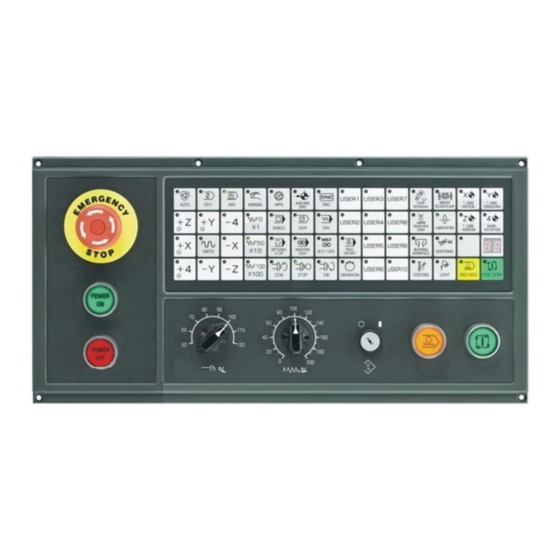
Chapter Four Operation Chapter Four Operation 4.1 Power ON/OFF 4.1.1 Power ON 1) Make sure all parts of the machine are wired correctly and secured. 2) Switch on the machine power according to its manual. 3) Press “POWER ON” button for 1-2 seconds to switch on the system power. 4) Make sure there is figure on the LCD after seconds as switching on the machine power. -
Page 208: Related Operations To Machine Panel
GSK983Ma Milling Machine Center CNC System User Manual 1) When the switch is off, all settings and program edit can not be executed. Related operations can be performed until the key switch is ON. 2) When the switch is off, only program EDIT can not be executed. - Page 209 Chapter Four Operation...
-
Page 210: Emergency Stop (Red)
GSK983Ma Milling Machine Center CNC System User Manual 4.3.2 Emergency Stop (red) In the emergencies, movements of all machine axes are stopped immediately by pressing Emergency Stop button. At the same time, the button is locked in the stop position. - Page 211 Chapter Four Operation Mode Functions (1)Programs in the memory can be performed (2)The sequence number of programs in the memory can be Auto mode searched (MEMORY) Used for the following operations: (1)Save program in the memory (2)Program alteration, insertion and deletion Edit mode(EDIT)...
-
Page 212: Operations Related To Manual Operation
GSK983Ma Milling Machine Center CNC System User Manual 4.3.4 Operations Related to Manual Operation In addition to operating automatically by program, the switch can be used for the following manual operations. 4.3.4.1 Jog Feed Machine can be operated by jog feed. -
Page 213: Handle Feed (Mpg)
Chapter Four Operation 180% 10.6 5.40 190% 14.6 7.40 200% 20.5 10.40 210% 28.3 14.40 220% 1000 39.4 20.00 230% 1400 55.1 28.00 240% 2000 78.7 40.00 1016 Note 1: Values listed in the table vary with different machines. Note 2: Error of the federate listed in the above table is approximately ± 3%. 4)Rapid traverse 1)... -
Page 214: Manual Absolute Value
GSK983Ma Milling Machine Center CNC System User Manual unit. ×1 indicates that movement amount is multiplied by 1; while ×10 indicates that movement amount is multiplied by 10; ×100 indicates that movement amount is multiplied by 100. MOVEMENT AMOUNT OF EACH SCALE Input system ×1... - Page 215 Chapter Four Operation X300.0 Y200.0 ;③ a) When the above block ① has been performed, block ② is performed after manual operation (Move 20.0 in X direction, move 100.0 in Y direction) b) Press FEED HOLD key during the execution of the block ②...
- Page 216 GSK983Ma Milling Machine Center CNC System User Manual e) When manual operation is followed by an incremental command, the position that the tool moves to is the same with that is commanded while manual absolute switch is set to OFF.
- Page 217 Chapter Four Operation Hold key is pressed. The end point PB of the current block transfers to point PB’ due to the offset as a result of manual operation and the vectors VB1 and VB2 of the original point PB also trasfer to VB1’ and VB2’ It’s not required to compensate the vector between the next two blocks (tool path from PB to PC and the path from PC to PD).
- Page 218 GSK983Ma Milling Machine Center CNC System User Manual (b)If manual operation is inserted after the execution of a block, the vectors VB1 and VB2 for the end points of the current block will be moved in parallel, and the method for determining the following path is the same with (a).
-
Page 219: Manual Reference Point Return (Reference Position)
Chapter Four Operation 4.3.5 Manual Reference Point Return (reference position) Manual operation may be used for zero return: 1)Select “Machine Zero” mode. 2)Select zero return direction for each axis to make it move towards the reference point. The machine rapidly moves to the deceleration point and then move towards to the reference point at speed FL (parameter Number 114). -
Page 220: Stop Automatic Running
GSK983Ma Milling Machine Center CNC System User Manual Note 1: Press “Cycle Start” key in “Edit” mode. Programs read in are stored. The way of storing is the same with that of press INPUT key in parameter setting. Note 2: “Cycle Start” key is invalid in the following conditions: (a)... -
Page 221: Transmit Processing Program From U Disk To The Memory By Usb Interface
Chapter Four Operation parameters are NC parameter N0340 and N0341.If USB interface is used as a input or output unit, set N0340 and N0341 to 0 separately. 4.3.6.3.2.2 Transmit machining program from U disk to the memory by USB interface Steps:1)Press key on NC unit,and related pages are displayed on LCD;... - Page 222 GSK983Ma Milling Machine Center CNC System User Manual 3)Press key on the small keyboard, operation options are displayed. The contents of the option can be selected by moving yellow cursor by UP/DOWN key. 4)When the yellow cursor is moved to “Copy program (UsbDisk->NcRam in edit mode”, press key to display file list of the machining program on U disk.
-
Page 223: Output Processing Program From Program Memory To U Disk By Usb Interface
Chapter Four Operation Copy key is used to load data; Refresh key is used to refresh contents on the screen. Usually, screen refresh is needed to update the contents when plug in or pull out U disk. Return key. Generally, there is no return key in the system for user to return the list of higher level on expanded menu. - Page 224 GSK983Ma Milling Machine Center CNC System User Manual Press key directly in Edit mode to copy all programs to U disk, and the file name is “983 Pro.txt”. If there is a file with a same name is in the U disk, the system will add a sequence Number with brackets behind the file name, for example: “983 Pro(1).txt”...
-
Page 225: Dnc Running
Chapter Four Operation 4.3.6.4 DNC Running 4.3.6.4.1 Capacity of DNC storage area and related parameter of USB interface In DNC running mode, input program to DNC storage area by USB interface, select program to be machined in DNC storage area to process. Capacity of DNC storage area is 160k bytes. - Page 226 GSK983Ma Milling Machine Center CNC System User Manual 3)Operation options are displayed by pressing key on the small keypad. Contents on the option can be selected by moving yellow cursor with UP/ DOWN cursor. 4) After yellow cursor is moved to “Copy PRO. (Usb Disk->DNC Vol.) in DNC mode”, press...
-
Page 227: Select Processing Program In Dnc Storage Area To Perform Dnc Machining
4.3.6.4.3 Select processing program in DNC storage area to perform DNC machining In order to meet the requirement for securely execute high capacity programs, the GSK983Ma system adopts 160M DNC memory area to store the programs to be machined. Many processing programs can be stored in DNC memory area to meet the requirements of different machining. - Page 228 GSK983Ma Milling Machine Center CNC System User Manual key is used to delete programs in DNCstorage area; key is used to confirm the machining program selected by the blue cursor; 2) When key is pressed, the processing program where the blue cursor locates is selected as the program for DNC machining, and the DNC program screen is entered automatically.
-
Page 229: Single Block
Chapter Four Operation 4.3.6.5 Single Block When SINGLE is valid, the control unit executes only a block each time when the “Cycle Start” key is pressed. When the “SINGLE BLOCK” is set to 1 in the page of the menu switch setting, the control equipment is stopped after performing one program. -
Page 230: Mdi Operation In Automatic Running
GSK983Ma Milling Machine Center CNC System User Manual 4.3.6.8 MDI Operation in Automatic Running (1) Make ”single block” function valid, when current block is executed, feed axis stops to wait the next command. (2) Select MDI mode. (3) Input required command, commands in MDI mode can be executed by pressing Cycle Start key. -
Page 231: Dry Run
Chapter Four Operation 4.3.6.11 Dry Run If Dry or “Dry Run” in menu switch of Setting is set to ON during the operation of the memory or MDI instruction, the F function is not active and the tool will move as the following speed. Rapid traverse key Rapid traverse Cutting feed... -
Page 232: Lock Key
GSK983Ma Milling Machine Center CNC System User Manual automatic running. 4.3.6.13 M.S.T. Lock Key M.S.T lock or “M.S.T lock” of menu switch in Setting is ON, M. S. T. and B function is locked, G function still executes, and this function is also used to program checking. -
Page 233: Rapid Traverse Override
Chapter Four Operation 4.3.6.16 Rapid Traverse Override Any rapid traverse switch with override 100%、50% and F0 can be set on the panel. When rapid rate is 10m/min, and the override is set to position 50%, actual feed speed is changed to 5m/min. F0 is a fixed speed provided by machine tool manufacturer (NC parameter is No. - Page 234 GSK983Ma Milling Machine Center CNC System User Manual 0001; 0001 G00……; …………………… …………………… Programs correspond to workpiece 01 120 M02; 0002; 0001 G00……; …………………… …………………… Programs correspond to workpiece 02 300 M30; 0004; 001 G00……… ……………………… ……………………… Programs correspond to workpiece 04 080 M02;...
-
Page 235: Mpg (Manual Pulse Generator) Interruption
Chapter Four Operation number, once sequence number or program number is retrived, set workpiece number to 00 and press START key again. Note 3:This function is not used for MDI running, but only for Automatic running. Note 4: If corresponding program number for workpiece number is not stored in memory, alarm (NO.59)will occurs by pressing START key. -
Page 236: Manual Spindle Function
GSK983Ma Milling Machine Center CNC System User Manual Signal Movement It is affected, that is, the tool does not move Machine locked if the machine is set to ON It is affected, that is, the relative coordinate Displayed locked does not change if the display is locked... - Page 237 Chapter Four Operation refer to machine tool builder’ s manual. Spindle orientation: When the machine is matched with servo spindle driver, the system will send orientation start signal to servo driver by pressing ORIENTATION key in Manual mode or Auto mode, MDI command M19.
-
Page 238: Manual Auxiliary Function
GSK983Ma Milling Machine Center CNC System User Manual 4.3.9 Manual Auxiliary Function The functions of the key and execution logic are determined by PLC programming, please refer to PLC user manual of corresponding version. They control ON/OFF of machine parts separately. - Page 239 Chapter Four Operation...
- Page 240 GSK983Ma Milling Machine Center CNC System User Manual Functional keys: Different screens are selected and displayed by functional keys. The names and contents of each functional key are listed bellow. Press Display the current position once Press Set the display and setting of data...
- Page 241 Chapter Four Operation Introduction for other keys on MDI keypad Reset key For CNC reset and alarm eliminating, etc. Input key When address key or numerical key is pressed, input data is displayed on screen but it still in buffer. Press input key, and these data are saved register.
-
Page 242: State Display
GSK983Ma Milling Machine Center CNC System User Manual... - Page 243 Chapter Four Operation (2)Alarm state display (3)Edit searching display (4)The system restart display (5)The background program is in editing (6)Stop drawing (7)It is in drawing...
-
Page 244: Key Input
GSK983Ma Milling Machine Center CNC System User Manual (8)Continuous drafting or single block selection The symbols displayed are as follows: NOT READY: It indicates that the control or servo system fails to operate. LSK: It indicates the symbol is skipped when data is input. -
Page 245: Display Of Program Number And Sequence Numbers
Chapter Four Operation data can not be input. Press D/H once to input D, and press again to input H. Only a word consisting of one address and a figure can be keyed in when program edit is not being performed. Pressing CANCEL to clear one word. In program editing, one or more words can be input, and a block or a string up to 32 characters can be entered. -
Page 246: Alarm Display (Functional Key Alarm )
GSK983Ma Milling Machine Center CNC System User Manual 4.4.4 Alarm Display (functional key ALARM ) When ALARM is indicated at right bottom of the screen in case of alarm occurs, warning messages may be visited by the following procedures: Press the... -
Page 247: Current Position Display And Reset (Functional Key Position )
Chapter Four Operation If operation information is needed to display after some other page is selected, press the ALARM key. When alarm message is displayed, press the ALARM key again. 4.4.6 Current Position Display and Reset (functional key POSITION ) (1)... -
Page 248: Display Of Command Value (Functional Key Command )
GSK983Ma Milling Machine Center CNC System User Manual (c) (MACHINE)Machine coordinate system (d) (DISTANCE TO GO)Distance to go DISTANCE TO GO indicates the remaining move amount of a block. The position of each coordinate system cannot be cleared in the ALL position interface. The unit of machine coordinate system is the same as that of machine system. -
Page 249: Setting (Functional Key Setting )
Chapter Four Operation (Ⅱ)It displays the command value input by MDI or the command value to be executed next time. (Ⅲ)It displays the command value of the next block to be executed during the tool nose radius compensation C. 4.4.8 Setting (functional key SETTING ) 4.4.8.1 Display and Setting of Input, Output, etc. - Page 250 GSK983Ma Milling Machine Center CNC System User Manual Setting (valid when the program lock is ON, invalid when it is locked, whose state can be switched by parameter 11 BIT5 DECI) (a) Set the mode selection to MDI mode. (b) Press the cursor key to move the cursor to the item to be altered. The cursor cannot be moved with the address key N.
- Page 251 Chapter Four Operation (Ⅱ)Other settings and display The displayed numbers and their meanings are as follows; Data Meaning number Running time (Unit: hr) (TMHOR) Running time (Unit: min) (TMMIN) Running time (Unit: s) (TMSEC) Canned cycle G73(high-speed peck drilling cycle), set retraction amount (CYCR) Canned cycle G83(deep-hole drill cycle), rapid feed is changed to specified distance (CYCD)of cutting federate.
-
Page 252: Display And Setting Of User Macro Program Variables
GSK983Ma Milling Machine Center CNC System User Manual I DVICE select the input device storing data to the memory. When the set input device is (INPUT DEVICE)2=1, this setting is valid. O DVICE select the output device that is used for data outputting or set by parameter. -
Page 253: Mdi Operation (Functional Key Command )
Chapter Four Operation the cursor goes beyond the current page. Method 2: Key in N, variables, press INPUT key to search the position of corresponding variable number. (a) Select MDI mode. (b) When the cursor is moved to the variable number to be changed, and P , variable number value are keyed in, press INPUT key to input setting value.(the setting value can be input after the protective lock is ON) 4.4.9 MDI Operation (functional key COMMAND ) -
Page 254: Mdi Start And Running
GSK983Ma Milling Machine Center CNC System User Manual (2)The method of deleting Y200.5 before the CYCLE START key is pressed. (a) Press Y ,DELETE,INPUT key in succession. (b) CYCLE START key on the panel of machine performs only X command. -
Page 255: Offset Of The Tool Position
Chapter Four Operation 4.4.12 Offset of the Tool Position Setting and display of tool nose radius compensation (functional key OFFSET) (1) Press OFFSET key. (2) Press PAGE key to display the required page. 1st page Offset number 1-12。 2nd page Offset number 13-24。... -
Page 256: Setting And Display Of Workpiece Origin Point Offset
GSK983Ma Milling Machine Center CNC System User Manual Note 1: When offset is changed in Automatic Running, new offset value is not valid until the offset Number is set to D or H command. Note 2: Clear all offset value by 0-9999 INPUT. -
Page 257: The Method Of Measuring Tool Length
Chapter Four Operation (3) Move the cursor to the Number to be altered Press cursor key ↑ or ↓ key to move the cursor in sequence. It will change to the next page if the cursor is over a page. (4)... - Page 258 GSK983Ma Milling Machine Center CNC System User Manual See Program number in Section 4.16 for displaying a selected program. Press PAGE key to display the contents of the program in sequence. By pressing key, the page is displayed in forward direction. By pressing key, the page is displayed in backward direction.
-
Page 259: Program Number Retrieving (Functional Key Program)
Chapter Four Operation AUTO mode and runit. At this time, the block locating at the cursor in Edit mode is read into the buffer register. (3) Modes other than Edit and AUTO mode Press PROGRAM key to display the screen contains the block being executed and the following blocks to be executed. -
Page 260: Input Program File With Multiple Programs
GSK983Ma Milling Machine Center CNC System User Manual Note 1: The fist and the last line of the program must be character “%”. Note 2: In the process of communication, it is not allowed to cut off the power, otherwise, alarm 101 occurs and the programs of the system will be lost. - Page 261 Chapter Four Operation Key in a block (d) [Example] When keying in G92 X500.0 Y200.0 M12: (e) If a keyed in character is incorrect, press the CANCEL key to delete the last keyed in character. By pressing the CANCEL key continuously it deletes the keyed in characters one by one from the back.
-
Page 262: Deletion Of A Program
GSK983Ma Milling Machine Center CNC System User Manual 4.4.20 Deletion of a Program (Valid when the program lock is ON) delete programs stored in the memory. (a) Select Edit mode. (b) Press PROGRAM . (c) Press O , program number, and DELETE keys, the program with this number is deleted. -
Page 263: Restart The Program
Chapter Four Operation started or restarted according to sequence number search. This block searched is usually a break point of a process. If program restarts search is necessary in machining, M, S, T, G codes and coordinate system should be specified in MDI, so as to search current state of the machine and NC system. - Page 264 GSK983Ma Milling Machine Center CNC System User Manual (d) Return to the start point of the program by pressing the cursor key ↑ . (e) Press P, Sequence Number cursor key ↓ to search the block to be restarted. If the same sequence number appears for many times.
- Page 265 Chapter Four Operation (c) The machine immediately stops due to storage type travel limit alarm. (d) The coordinate system changes after the last automatic operation. Example: (i)Specify G92 command through MDI. (ii)Move the coordinate system (iii)Set the automatic coordinate system after reference point returning. (iv)Press SHIFT key.
-
Page 266: Comparison And Stop Function For Block
GSK983Ma Milling Machine Center CNC System User Manual Note 6: Set the manual absolute switch to ON position for manual operation no matter it is before or after machining. When a program restarting operation instead of resetting is performed after manual... -
Page 267: Input Offset Value (Any Functional Key)
Chapter Four Operation 4.4.27 Input Offset Value (any functional key) (1) Format Key in offset value from input device (PC or USB switch box) as the following format: G10. P p R r P: Offset number r: Offset value (G90 is absolute input, G91 is incremental input) Note : Because G10 is a non-modal code, each offset value must headed with G10 and ended with %(ISO). - Page 268 GSK983Ma Milling Machine Center CNC System User Manual According to the definition, a word is also an edit unit. On the basis of the following explanations about edit, strictly speaking, word shall be called “edit unit” Note 2: During program execution, machining is temporarily stopped by single block stop, feed hold and other functions.
- Page 269 Chapter Four Operation (3)Continuous search can be conducted by pressing down and holding the cursor ↓ or ↑ key. (4)The next page is displayed and search starts from the beginning of the page by pressing the page ↓ key. (5)The previous page is displayed and search starts from the beginning of the page by pressing the page ↑...
- Page 270 GSK983Ma Milling Machine Center CNC System User Manual 4.4.30.3 Address Search Search a specified address from the present position forward. N1234×100.0 Y1250:X1234:N5678, M03: Current word The M03 to be indexed Key in M . (1) Press the cursor ↓ key to start search. The cursor is displayed underneath M after the search.
- Page 271 Chapter Four Operation (a) See 4.24.1 for scanning. (b) See 4.24.2 for word search. When Y1250 is in front of the currently indicated position, first move the cursor to the beginning of the program. (2) Key in T , 1 , 0 , 5 , and press INSERT key.
- Page 272 GSK983Ma Milling Machine Center CNC System User Manual (2) Key in M , 1 , 5 ,and press ALTER key. N1234×100.0 Y1250:M15: S1234: Altered program 4.4.30.7 Insertion and Alteration of Words, Blocks and Strings (Active when program lock is ON)...
- Page 273 Chapter Four Operation Y1250 2.5 M20. 4.4.30.8 Word Deletion (valid when the program lock is ON) N1234 ×100.0 Y1250 T105: X1234: Delete Y1250 (1) Search and scan the word to be deleted. (2) Press the DELETE key. N1234 ×100.0 T105: X1234: The block after deletion 4.4.30.9 Deletion of the Contents before EOB...
- Page 274 GSK983Ma Milling Machine Center CNC System User Manual 4.4.30.12 Display of All Stored Program Numbers Once the contents of the memory described in 4. 4.30.11 are sorted, all stored program numbers are displayed. 4.4.30.13 Edit of User Macro Program (valid when program lock is ON) User macro program can be edited by SHIFT key in Edit mode with the program lock switch is released.
- Page 275 Chapter Four Operation (ii)At the / of an optional block skipped over (iii)At the left beginning # of a substitution statement (iv)Position (·=)OR; (v)At the characters headed with IF, WHILE, GOTO, END, DO On the LCD screen, there is a blank for a character before the characters above. Deletion, alteration and insertion can be performed in the area between the front and rear cursor position.
- Page 276 GSK983Ma Milling Machine Center CNC System User Manual Note: The alarm occurs in background edit has no effect on the foreground execution. Similarly, the alarm occurs in foreground execution has no effect on the background edit. The program of foreground execution can be viewed in background edit. However, alarm (NO.160) occurs if the program being executed at foreground is changed.
- Page 277 Chapter Four Operation be set by the following signals on the NC unit. (1) (SINGLE BLOCK) (2) (DRY RUN) (3) (AUX FUNC . LOCK) (4) (MACHINE LOCK) (5) (DISPLAY LOCK) (6) (MANUAL ABSOLULE) (7) (Z-AXIS NEGLUTE) (8) (X、Y、Z、A、5 MIRROR IMAGE) (9)...
- Page 278 GSK983Ma Milling Machine Center CNC System User Manual 4.4.33 Operation for LCD Soft Functional Key 4.4.33.1 Introduction Functional keys (POSITION,PROGRAM,OFFSET,……etc.) here are taken as soft functional keys, which significances are displayed on LCD. The introductions for each page that gotten by pressing soft functional key are as follows.
- Page 280 GSK983Ma Milling Machine Center CNC System User Manual Press DIR key to display the program list. The displayed program list is as follows: (3)Offset display Press OFFSET key to display the corresponding offset of each tool number on the LCD. Select required data by press page key ↑...
- Page 281 Chapter Four Operation (4)Display of command Press Command key to display the following figure: Then press PAGE key, the content is changed as the following figure.
- Page 282 GSK983Ma Milling Machine Center CNC System User Manual (5)Function setting Press Setting key to display the figure as follows.
- Page 283 Chapter Four Operation Press Setting functional key, and various set data are displayed on the screen. The setting of operating time is displayed on the second page by pressing Page key. Press MACRO key, and local variable and common variable of user macro program are displayed on the screen of LCD.
- Page 284 GSK983Ma Milling Machine Center CNC System User Manual (6)Alarm and operation information display Press ALARM functional key to display alarm content as shown in the above figure. Press EX.MSG key to display the outside message as shown in the following figure.
- Page 285 Chapter Four Operation Press NC.PARor PLC.PAR key to display related system parameter on LCD. Press page key ↑ or ↓ and cursor key ↑ or ↓ to display required parameters. (8)Diagnosis data display Each page displays 160 diagnosis data by pressing DGNOS functional key.
- Page 286 GSK983Ma Milling Machine Center CNC System User Manual 4.4.33.4 Measure Function of Workpiece Coordinate System Current machine tool coordinate can be set to related workpiece coordinate system automatically by workpiece coordinate measure function with MEASURE key, which facilitats the setting of workpiece coordinate.
-
Page 287: Output Of Nc Parameter
Chapter Four Operation Fig. 4.4.3.6 G57:Workpiece origin offset value of workpiece coordinate system 4(G57) G58:Workpiece origin offset value of workpiece coordinate system 5(G58) G59:Workpiece origin offset value of workpiece coordinate system 6(G59) Steps of setting the workpiece coordinate system by using the measure function of workpiece coordinate system: (1) Move the cursor to the sequence number of workpiece coordinate system to be altered. -
Page 288: Graphic Function
GSK983Ma Milling Machine Center CNC System User Manual (d) Press down the emergency stop button on the operation panel. (e) Input P -9999 in succession, and press Data input key. The above operations are performed, NC parameters are input from computer or USB switch box, and set to NC parameter storage. -
Page 289: The Meaning Of Graphic Parameter
Chapter Four Operation Press cursor key ∨ or ∧ to move the cursor to the parameter to be set. Press P + data, [INPUT] key to input graphic parameter. 4.5.3 The Meaning of Graphic Parameter 4.5.3.1 Program Name When the value is set to a negative number, which indicates the graphic is drawn by dynamic graphic display function, namely, the tool path of the program being executed is drawn on the screen. -
Page 290: Range (Maximum), (Minimum)
GSK983Ma Milling Machine Center CNC System User Manual 4.5.3.4 Range (maximum), (minimum) Set the max. or min. value of drafting range on the screen. Value(MAX) , Value (MIN) 0, 0, 0, Setting range:0~±99999999 1=0.001mm or 0.0001inch(usually) 1=0.0001mm or 0.00001inch(input unit /10)... -
Page 291: Scaling
Chapter Four Operation Starting point of the program (70,120) Drawing for the whole tool path If the maximum and minimum values are set as follows Value Value(MIN) (MAX) , 70000, 0, 120000, The graphic center is(35000,60000) The scaling is set automatically Drawing for the shadow part Value(MAX)... - Page 292 GSK983Ma Milling Machine Center CNC System User Manual Graphic dimension The above figure indicates that the maximum graphic range of LCD covers 150.4mm horizontally and 112.8mm vertically. If the drawing scope is over this range, the scale that ranges from 0.01~...
-
Page 293: Rotation Angle
Chapter Four Operation 4.5.3.6 Rotation Angle The parameter indicates the rotation of three dimension graphic, it is valid only in three dimension graphic. Setting range: -180~180 degree On LCD, tool path is defined by the workpiece coordinate value of tool moving, and corresponding workpiece origin of the LCD center.. -
Page 294: Start Point
GSK983Ma Milling Machine Center CNC System User Manual Graphic center in horizontal position = (600000 +300000)/ 2 = 450000 Scale = 150.4 / 300 = 0.501 Graphic center in vertical position = (500000+300000)/ 2 = 400000 Scale = 112.8 / 200 = 0.564 Scaling = Min. - Page 295 Chapter Four Operation Start and stop drafting are switched by pressing Menu (Drafting) (Stop) on Graphic interface. Continuous and single block are switched by pressing [continuous/single] key. As for rapid moving, the tool path is indicated by a dot line (----------------), as for cutting moving, the tool path is indicated by a full line (———).
- Page 296 GSK983Ma Milling Machine Center CNC System User Manual...
-
Page 297: Appendix
Appendix APPENDIX Appendix 1 System Version Display The system version is displayed immediately after power-on. -
Page 298: Appendix 2 G Codes List
GSK983M3Ma Milling Machine Center CNC System User Manual Appendix 2 G Codes List G code Group No. Function Positioning (rapid traverse) G00* Linear interpolation (cutting feed) G01* Circular interpolation (CW) Circular interpolation (CCW) Dwell Hypothetical axis assignation Exact stop check Offset amount, origin point offset amount setting XY plane selection G17*... - Page 299 Appendix 2. G Codes List Drilling cycle, spot boring Drilling cycle, spot facing Peck drilling cycle Tapping cycle Boring cycle Boring cycle...
-
Page 300: Appendix 3 Range Of Command Values
GSK983Me 铣床加工中心数控系统 使用手册 Appendix 3 Range of Command Values mm Input inch Input mm Input inch Input mm Output mm Output inch Output inch Output 0.001mm 0.0001inch 0.001mm 0.0001inch Least input increment 0.001° 0.001° 0.001° 0.001° Maximum stroke (start from reference ±99999.999mm ±99999.999mm ±3937.0078inch... -
Page 301: Appendix 4 Nomographs
Appendix 4. Nomographs Appendix 4 Nomographs A4. 1 Tool Path at Corner (1) General When servo system delay (due to exponential acceleration/deceleration at cutting or caused by the positioning system when a DC servo motor is used) is accompanied by cornering, a slight deviation is produced between the tool path (tool center path) and the programmed path as shown in Fig. - Page 302 GSK983M3Ma Milling Machine Center CNC System User Manual 2 = V·cosφ2 2 = V·sinφ2 π-(φ1-φ2)=θ [Description of symbols] V: Feedrate at both blocks before and after cornering 1: X-axis component of feedrate of preceding block 1: Y-axis component of feedrate of preceding block 2: X-axis component of feedrate of following block 2: X-axis component of feedrate of following block θ: Corner angle...
- Page 303 Appendix 4. Nomographs ⎧ ⎫ ⎛ ⎞ ⎛ ⎞ − ⎪ ⎪ ⎜ ⎜ ⎟ ⎟ ⎜ ⎜ ⎟ ⎟ × − − × − − − …………(6) ⎨ ⎬ − ⎪ ⎩ ⎪ ⎭ ⎝ ⎠ ⎝ ⎠ A4.2 Radius Direction Error at Circle Cutting When a DC servo motor is used, the positioning system will produce a delay between input axis and output axis.
-
Page 304: Appendix 5 Parameters
GSK983Ma Milling Machine Center CNC System User Manual Appendix 5 Parameters Displaying and setting parameter When the NC connected to the servo motor or a machine tool, to fully utilize the characteristic of the servo motor, parameters are set to determine the specifications and functions of the machine. The setting of parameters depends on the machine. - Page 305 Appendix 5. Parameters to be set is selected, the cursor will appear below the number. (The cursors can also select the pages.) Set the parameter by pressing + setting data + Press key if the data is mis-input. (f) Confirm the setting. (g) After the parameter setting is completed, switch the PRM.
- Page 306 GSK983Ma Milling Machine Center CNC System User Manual 1: When M30 is commanded, if the FIN signal sent to the machine side returns, the first block of the program is executed continuously. If the external reset signal rather than FIN signal returns, the system returns to the head of the program and enter into reset status (in AUTO mode).
- Page 307 Appendix 5. Parameters 0: Does not output the M code in canned cycle; stop the outputting spindle; spindle reverse rotation SRV. (canned cycle) 1: The outside area of stored stroke limit 2 is the prohibited area. 0: The inside area of stored stroke limit 2 is the prohibited area. 1: Outputs the external motion signal EF when the G81 execution is ending (Z axis does not move).
- Page 308 GSK983Ma Milling Machine Center CNC System User Manual SETE 1: “SETTING” is enabled when the program lock is ON. 0: “SETTING” is disabled when the program lock is ON. DECI 1: Decelerates if the signal is “1” when returning to reference point 0: Decelerates if the signal is “0”...
- Page 309 Appendix 5. Parameters 4 1 0 DMR 5 DMR 5 DMR 5 GRD 5 GRD 5 GRD 5 GRD 5 DMRX, DMRY, DMRZ, DMR4, DMR5 respectively set the detection multiplying ratios used on X, Y, Z, 4th, 5th axes. Set codes Multiplication Bit6 Bit5...
- Page 310 GSK983Ma Milling Machine Center CNC System User Manual 10° 10000 01111001 inch 12° 6000 01010101 inch 16° 8000 01110111 inch 0 1 8 IPL2 CPF2 CPF1 CPF2, CPF1 set the pulse frequency of backlash compensation (for all axes). Frequency CPF2 CPF1 (must be set to 256KHZ)...
- Page 311 Appendix 5. Parameters 16ms over 16ms 32ms over 32ms 48ms over 48ms 64ms over 64ms 80ms over 80ms 96ms over 96ms 112ms over 112ms 128ms over 128ms 144ms over 144ms 160ms over 160ms 176ms over 176ms 192ms over 192ms 208ms over 208ms 224ms...
- Page 312 GSK983Ma Milling Machine Center CNC System User Manual PMXY2, PMXY1 tool return direction is set in canned cycle G76 or G87 (valid when SIJ = 0) PMXY2 PMXY1 Return direction +X -X +Y -Y RS43 1:The offset vector of G43/G44 is hold after resetting.
- Page 313 Appendix 5. Parameters 1: In the part program edit area, the parity check is performed. 0: In the part program edit area, the parity check is not performed. In check prepared state, the parameter is automatically set to 1 and cannot be enabled/disabled externally.
- Page 314 GSK983Ma Milling Machine Center CNC System User Manual + setting value B, the multiplying ratio is between 2~48 Setting value =2× (CMR) Note: The command multiplying ratio here is an integral value. 0 3 1 VLOCX 0 3 2 VLOCY...
- Page 315 Appendix 5. Parameters 0 3 9 PECZRX 0 4 0 PECZRY 0 4 1 PECZRZ 0 4 2 PECZR4 4 1 6 PECZR5 PECZRX~5 set the pitch error origin point for X, Y, Z, 4th, 5th axes respectively. Setting value: 0~127 Setting some points corresponding to reference point (machine zero point), for example, the pitch error origin point is set to 0, the setting point 1 is in position +8.000mm, thus compensation range of the setting point 127 in position 1016.000mm is 0 mm~1016.000mm.
- Page 316 GSK983Ma Milling Machine Center CNC System User Manual 0 5 4 MACINTOF MACINTON: Custom macro interrupts invalid M code Setting value: 03~97 This parameter is valid when the parameter No.25 bit 4 MPRM=1. 0 5 7 TMHOR (h) 0 5 8...
- Page 317 Appendix 5. Parameters 0 6 3 ZDL5 EX5NG HIRS G605 ADL5 1: The 5th axis is linear axis. 0: The 5th axis is rotary axis. HIR5 1: The manual handle interruption for the 5th axis is valid 0: The manual handle interruption for the 5th axis is invalid. EX5NG 1: The ignore signal for the 5th axis is valid.
- Page 318 GSK983Ma Milling Machine Center CNC System User Manual 0 6 8 CYCD CYCD sets the distance value “d” when changing from rapid traverse to cutting feed in canned cycle G83 (peck drilling cycle). It should be set before peck drilling cycle (G83).
- Page 319 Appendix 5. Parameters CRCDL In cutter compensation C mode, when the outside machine along the acute angle approaching 90° is performed, the maximum ignore value of the move distance is set. Setting value: metric input 0~16383 unit: 0.001mm Inch input 0~16383 unit: 0.0001inch When X≤CRCDL,...
- Page 320 GSK983Ma Milling Machine Center CNC System User Manual 4 2 7 SERR5 SERRX, SERRY, SERRZ, SERR4, SERR5 respectively set the positional deviation limit when the X, Y, Z, 4th, 5th axes are moving. Setting value: 0~32767 detection unit (standard setting value 10000) Alarms 411, 421, 431, 441, 451 occur when out of the range.
- Page 321 Appendix 5. Parameters Reference value(detection unit: 1/1000mm h) Mechanical Servo loop gain multiplying ratio movement per 10V/1500r/mi 10V/2000r/mi 10V/2500r/mi revolution (unit: mm or deg) 1365 1024 1706 1280 1024 2275 1706 1365 2730 2048 1638 3413 2560 2048 4551 3413 2730 6826 5120...
- Page 322 GSK983Ma Milling Machine Center CNC System User Manual 0 9 8 LINTZ 0 9 9 LINT4 4 2 9 LINT5 LINTX, LINTY, LINTZ, LINT4, LINT5 respectively set the time constant of linear acceleration and deceleration for X, Y, Z, 4th, 5th axes (for rapid traverse).
- Page 323 Appendix 5. Parameters Setting value: 6~15000 unit: mm/min(metric output) 6~6000 unit: 0.1inch/min (inch output) 1 0 8 FEDFL FEDFL sets the floor level of exponential acceleration/deceleration in cutting feed (FL). Setting value: 6~15000 unit: mm/min 6~6000 unit: 0.1inch/min Usually, the value is 0. 1 0 9 JGFLX 1 1 0...
- Page 324 GSK983Ma Milling Machine Center CNC System User Manual 1 1 9 SPDLC SPDLC sets the spindle speed zero-drift compensation value, i.e. the zero-drift compensation value of the spindle speed command voltage. (S analog output A/B) Setting value: 0~±8191 unit:VELO 1 2 1...
- Page 325 Appendix 5. Parameters GRHMIN when the S4-digit (binary 12-digit output A or analog output A) is selected, it sets the floor level of spindle speed at high gear. Setting value:1~9999 unit: r/min。 Note: The setting value should be greater than the maximum spindle speed at low gear. (Refer to parameter No.
- Page 326 GSK983Ma Milling Machine Center CNC System User Manual 1 4 6 LT141 4 3 3 LT151 1 4 7 LT1X2 1 4 8 LT1Y2 1 4 9 LTIZ2 1 5 0 LT142 4 3 4 LT152 1 5 1 LT2X1...
- Page 327 Appendix 5. Parameters 0~±99999999 unit: 0.0001inch (inch output) 0~±99999999 unit: 0.001° (rotary axis) 1 6 3 PECINTX 1 6 4 PECINTY 1 6 5 PECINTZ 1 6 6 PECINT4 4 3 6 PECINT5 PECINTX, PECINTY, PECINTZ, PECINT4, PECINT5 respectively set the pitch error compensation intervals.
- Page 328 GSK983Ma Milling Machine Center CNC System User Manual In F1 command, when the feedrate is changed by the MPG, the parameter value is changed at the same time. 3 0 5 G604 G60Z G60Y G60X G60X, G60Y, G60Z, G604 respectively set the approaching direction of single-direction positioning for the X, Y, Z, 4th axes.
- Page 329 Appendix 5. Parameters (This parameter is valid only when the auxiliary axis is rotary axis.) TMCR 1: The custom macro programs (O9000) are called by T code. 0: The custom macro programs (O9000) cannot be called by T code. SALM 1: When the S code in the S4-digit (binary 12-bit output A or analog output A) exceeds the ceiling/floor level value output to the spindle, an alarm is issued.
- Page 330 GSK983Ma Milling Machine Center CNC System User Manual Note: This parameter is valid when S 12-digit output A or S analog output A is selected. RSTB 1: The reset in-progress signal is not output when emergency stop, external reset, reset & rewind are performed.
- Page 331 Appendix 5. Parameters Note: When parameter FXOS(NO.022—Bit0)=1, M05 is not output, but M04 or M03 is output directly. 3 0 9 TLSK GST2 GST1 LCTM TLCK 1: Inputs the group number during skip cutting. 0: Does not input the group number during skip cutting. GST1, GST2 specify the storable group numbers.
- Page 332 GSK983Ma Milling Machine Center CNC System User Manual 0: output RSCB1, RSCB 2, RSCB 3, RSCB 4 when the input/output devices 1,2,3,4 are used, the control code (DC1~DC4) are: 1: not used 0: used STP21, STP22, STP23, STP24 When the input/output devices 1,2,3,4 are used, the number...
- Page 333 Appendix 5. Parameters SLOW 1: The set parameter for clamping value at the lowest spindle revolution in constant surface control mode can be applied to all gears.(parameter No. 347) 0 : sets separately to each gear(parameter No. 343, 344, 345, 346) BDEG 1: the B axis input unit is 0.001°(B1=0.001°).
- Page 334 GSK983Ma Milling Machine Center CNC System User Manual 3 1 6 CDSCG the DSCG feedback (for rotating transformer and inductosyn) frequency detection is not performed. the DSCG feedback (for rotating transformer and inductosyn) frequency detection is performed. (This parameter is set to 0 after initialization) ACMR 1: CMP setting can be performed.(caution)...
- Page 335 Appendix 5. Parameters When linear interpolation (G01) is specified, the feedrate that exceeds the value set by the parameters is limited. Limit value on X,Y, Z axes and auxiliary axis is set separately. During the execution of circular interpolation, the tangential speed which exceeds the value set by the parameter is limited. [ A type ] (1)...
- Page 336 GSK983Ma Milling Machine Center CNC System User Manual 3 3 0 UMGCD7 G code that calls macro program O9017 3 3 1 UMGCD8 G code that calls macro program O9018 3 3 2 UMGCD9 G code that calls macro program O9019 。...
- Page 337 Appendix 5. Parameters communication setting (such as baud rate) is set by parameter No.311 3 4 2 PSKPFL PSKPFL skip cutting FL speed (for all axes) Setting value: 6~150000 unit: 1mm/min (metric output) 6~6000 unit: 0.1 inch/min (inch output) 3 4 3 GRMIN1 3 4 4 GRMIN2...
- Page 338 GSK983Ma Milling Machine Center CNC System User Manual 3 5 7 EXOFSX 3 5 8 EXOFSY 3 5 9 EXOFSZ 3 6 0 EXOFS4 4 4 2 EXOF5 EXOFS X, EXOFS Y, EXOFS Z, EXOFS 4, EXOFS 5 respectively set the external workpiece offset amount of the X, Y, Z, 4th, 5th axes.
- Page 339 Appendix 5. Parameters 3 6 9 REF3Z 3 7 0 REF34 4 3 8 REF35 REF3X, REF3Y, REF3Z, REF34, REF35 respectively set the distance from the 3rd reference point to the 1st reference point. Setting value: 0~±99999999 unit: 0.001mm (metric output) 0~±99999999 unit: 0.0001inch (inch output) 3 7 1 REF4X...
- Page 340 GSK983Ma Milling Machine Center CNC System User Manual The distance from the set origin point to the 1st reference point is set in inch system. Setting value : 0~99999999 unit: 0.0001inch Note:When both the metric and inch system are available, parameters No. 375~378, 411 are needed to be set.
- Page 341 Appendix 5. Parameters 3 9 5 ZOFS4 X 3 9 6 ZOFS4 Y 3 9 7 ZOFS4 Z 3 9 8 ZOFS4 4 4 4 6 ZOFS4 5 ZOFS4X, ZOFS4Y, ZOFS4Z, ZOFS44, ZOFS45 respectively set the 4th workpiece origin offset amount (G57) of X, Y, Z, 4th, 5th axes.
- Page 342 GSK983Ma Milling Machine Center CNC System User Manual Setting value: 0~99999999 unit: 0.001 time This value is the one when P is not commanded in G51 block. 4 0 8 When a value equals to the value set by parameter No.168, program O9000~O9899 are in unlocked state;...
- Page 343 Appendix 5. Parameters 1: English display 6 3 3 ROTR sets whether the angle command R value is incremental or absolute in coordinate system rotation command G68. 1: Determined by G90/G91 0: Absolute value 7 1 6 RTANGL RTANGL sets the default value of unspecified angle in rotation command G68 block. Setting value: 0~360000 unit: 0.001deg This value is valid when it is unspecified in G68 block.
-
Page 344: Appendix 6 Alarm List
GSK983Ma Milling Machine Center CNC System User Manual Appendix 6 Alarm List Contents Remark Turn OFF the power after setting a parameter and then turn ON the power. TH alarm (a character with incorrect parity is input in the significant area) TV alarm (the number of characters in a block is odd). - Page 345 Appendix 6. Alarm List An intersection cannot be obtained by using the cutter compensation C intersection calculation. Or a corner angle less than 90° intersection calculation is specified in cutter compensation B. Compensation “start” or “cancel” is performed in G02/G03 mode during the execution of cutter compensation.
- Page 346 GSK983Ma Milling Machine Center CNC System User Manual not found. The program after communication is different with the original one. (program comparison) Programs cannot be edited because the commands for start point, end point or movement end point are incorrect in the extended edit function.
- Page 347 Appendix 6. Alarm List A value not defined as a variable number is designated in the custom macro. The left side of substitution statement is a variable whose substitution is inhibited. The nesting of bracket exceeds the ceiling level (quintuple) The SQRT argument is negative or BCD argument is negative.
- Page 348 GSK983Ma Milling Machine Center CNC System User Manual Index table When decimal point is used in B axis command, a non-integral value is indexing specified or a value rather than the integral multiple of the minimum indexing function angle in the index table is specified.
- Page 349 Appendix 6. Alarm List When the 5th axis moves along the + direction, the tool enters into the inhibited area defined by a stroke limit 1. When the 5th axis moves along the - direction, the tool enters into the inhibited area defined by a stroke limit 1.
- Page 350 GSK983Ma Milling Machine Center CNC System User Manual The position deviation value in Y axis moving state exceeds the setting value. The deviation value of Z axis is excessive. (more than 500 VELO) The position deviation value of Z axis exceeds ±32767, or the speed command value of DA converter is beyond the range +8191~...
- Page 351 Appendix 6. Alarm List The PLC program is unloaded. (Only PLC-Model A). The communication between NC and PLC is incorrect or interrupted. The MPU of PLC-Model B cannot be kept. An alarm is generated in the MPU of PLC-Model B. RAM/ROM parity error occurs in the MPU of PLC-Model B.
- Page 352 GSK983Ma Milling Machine Center CNC System User Manual CPU alarm (Execute the INT command) The auxiliary RAM option is added but RAM is not installed. ROM parity error (PLC-MODEL A ROM) ROM parity error (basic ROM) ROM pairing error (low and high byte inconsistent)
-
Page 353: Appendix 7 Status When Turning Power On, Reset And Cleared
Appendix 7. Status List Appendix 7 Status when Turning Power on, Reset and Cleared O.the status is not changed or the movement is continued. X.the status is cancelled or the movement is interrupted. Item Power-on Status Cleared Status Reset Status Offset value ○... - Page 354 GSK983Ma Milling Machine Center CNC System User Manual Alarm indicator light is out when The same as left The same as left no alarm occurs ×(light ON when ×(light ON when NOT READY × emergency stop) emergency stop) MDI mode : ○...
-
Page 355: Appendix 8 Stored Pitch Error Compensation Function
Appendix 8 Stored Pitch Error Compensation Function Appendix 8 Stored Pitch Error Compensation Function A8. 1 Function Pitch error compensation is performed with the least command increment for all axes. This function is enabled after reference point return. A8. 2 Specification The tool position after reference return is called compensation origin point. - Page 356 GSK983Ma Milling Machine Center CNC System User Manual P E C Z R Y P E C Z R Z P E C Z R 4 P E C Z R 5 PECZRX, PECZRY, PECZRZ, PECZR4, PECZR5: pitch error origin point.
- Page 357 Appendix 8 Stored Pitch Error Compensation Function Note: The data in “( )” is the measured result is incremental value, i.e. positive error indicates excessive movement, and negative error indicates insufficient movement. Compensation point 0 corresponds to the reference point ;compensation point 1 corresponds to the one after the reference point moveing 10000μm along the positive direction;...
- Page 358 GSK983Ma Milling Machine Center CNC System User Manual Machine Position Measured Corresponding Compensation Result Parameter Number Value 1000 -590000~-600000 … … … … 1058 -10000~-20000 1059 0 ~ -10000 1060 1061 0~10000 1062 10000~20000 … … … … 1127 660000~670000 In the table above, set +7 as the compensation amount in the range -10000~-20000;...
- Page 359 Appendix 8 Stored Pitch Error Compensation Function set -3 as the compensation amount in the range -40000~-50000; set +7 as the compensation amount in the range -30000~-40000; set 0 as the compensation amount in the range -20000~30000; set -2 as the compensation amount in the range -10000~20000 When the X axis moves from -40000 to the reference point, the total pitch error compensation amount (+3)+(-7)+(0)+(2)=(-2)...
- Page 360 GSK983Ma Milling Machine Center CNC System User Manual The compensation value is +3(-5)when the tool moves along the “+” direction and reaches the compensation point. The compensation value is +3(-5)when the tool moves along the “-” direction and reaches the compensation point.
- Page 361 Appendix 8 Stored Pitch Error Compensation Function Limitation: (Valid pitch error compensation value) × (pitch error compensation magnification) ×CMR The result should be within the range ±127. Otherwise, the compensation will be performed incorrectly. In some case, if a value exceeding ±127 is needed, the exceeding part can be divided and added to the adjacent point for compensation.
-
Page 362: Appendix 9 Operation List
GSK983Ma Milling Machine Center CNC System User Manual Appendix 9 Operation List Memory total clearance Press Power-on - the same time to turn on the power Parameters clearance Clear Press Power-on - the same time Programs clearance Press Power-on -... - Page 363 Appendix 9 Operation List Offset value input →offset Any mode Offset No.→ → →offse t data→ Setting data Move the cursor the setting input No. to be changed→ MDI mode Setting →data→ Parameter output EDIT mode Parameter → - 9999 - Offset output EDIT mode Offset...
- Page 364 GSK983Ma Milling Machine Center CNC System User Manual Search program number EDIT mode Program ○ → (cursor ) (stored memory) Search sequence →sequence number AUTO mode Program (stored EDIT mode memory) No.→ (cursor) Search Word search Input the address and data to...
- Page 365 Appendix 9 Operation List Delete words Search a word to be deleted→ EDIT mode Program Alter words Search a word to be altered→address→data— EDIT mode Program Insert words Search a word before which another word to be inserted→address→data→ EDIT mode Program Memory EDIT mode...
-
Page 366: Appendix10 Program Lock
GSK983Me 铣床加工中心数控系统 使用手册 Appendix10 Program Lock A10.1 General Programs numbered 9000~9899 can be locked with passwords. In locked state, program number 9000~9899 cannot be displayed, edited or output. Password function can protect the special programs written by the machine tool builder; moreover, it can prevent these programs from accidental deletion A10.2 Program number Only program numbers O9000~O9899 can be locked. - Page 367 Appendix 10 Program Lock (b) Cut off the NC power and turn ON again. Parameter No. Locked Store the password Setting range: 1~99999999 Released Input a value the same as the one in parameter No. 168, and then the locked state is released. Input a different value, the lock is enabled.
-
Page 368: Appendix 11 Usb Interface Parameter Transfer Operation
GSK983Ma Milling Machine Center CNC System User Manual Appendix 11 USB Interface Parameter Transfer Operation A11.1 General By using USB interface, the NC parameters or PLC parameters can be transferred. A11.2 Parameter setting method NC parameter No. 340 (for input device) and parameter No. 341 (for output device) can be set to 0. -
Page 369: Appendix 12 System Clock Setting And Plc Programming
Appendix 11 USB Interface Parameter Transfer Operation Appendix 12 System Clock Setting and PLC Programming A12.1 System clock setting A12.1.1 Enter into system clock management page The clock is set in the system management page after system power-on. Press “SHIFT” key in system version display screen to bring up system management page. - Page 370 GSK983Ma Milling Machine Center CNC System User Manual After pressing “YES” key, the user can set the contents in the system; the system automatically sets the modification permissions according to the user levels. The user can store the setting into the system by pressing “YES” key after modification.
- Page 371 Appendix 11 USB Interface Parameter Transfer Operation...
- Page 372 GSK983Ma Milling Machine Center CNC System User Manual Use the arrow up and down to select the corresponding options: System setup, Program Ladder From UsbDisk, Backup Ladder File. (1) System setting and permitted operation (2) PLC files display and permitted operation when programming in U disk:...
- Page 373 Appendix 11 USB Interface Parameter Transfer Operation Please refer to GSK983Ma PLC programming manual for the details of PLC programming.
Need help?
Do you have a question about the GSK983Ma and is the answer not in the manual?
Questions and answers