Sign In
Upload
Manuals
Brands
GSK Manuals
Control Systems
GSK983Ma
GSK GSK983Ma Manuals
Manuals and User Guides for GSK GSK983Ma. We have
1
GSK GSK983Ma manual available for free PDF download: User Manual
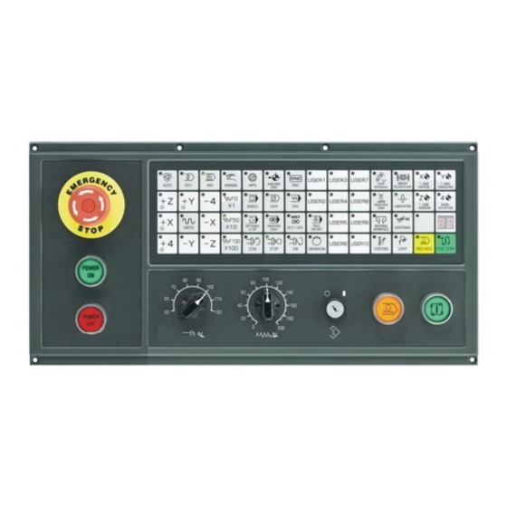
GSK GSK983Ma User Manual (373 pages)
Brand:
GSK
| Category:
Control Systems
| Size: 5 MB
Table of Contents
Table of Contents
7
Programming
13
Chapter One General
13
General
13
Chapter Two Specification
15
Manual
18
Chapter Three Programming
25
What Is Programming
25
Program Structure
25
Block
26
Program Word
26
Input Format
28
Decimal Point Programming
29
The Maximum Command Value
30
Program Number
31
Sequence Number
32
Skip to Optional Block
32
Dimension Word
33
Controlled Axis
33
Setting Unit
34
The Least Input Increment and the Least Movement Unit
34
Folds Input Unit
35
The Maximum Stroke
36
Program Origin and Coordinate System
36
The Coordinate System and the Machining Start Point
36
Workpiece Coordinate System
37
Reference (Position) Point
38
Absolute and Incremental Commands
38
Feed Function (Ffunction )
39
Rapid Traverse Rate
39
Cutting Feedrate
40
Feedrate Decelerates to 1/10
41
Synchronous Feed (Feed/Rev.)
41
F1-Digit Feed
42
Automatic Acceleration/Deceleration
42
Automatic Corner Modification
43
The Automatic Modification of Inner Corner
43
The Change of Inner Side Arc Cutting
46
Preparation Function (Gfunction )
47
Plain Selection (G17, G18, G19)
50
Positioning (G00)
50
Single Direction Positioning (G60)
51
Linear Interpolation (G01)
52
Circular Interpolation (G02, G03)
54
Circular Interpolation Without an Additional Axis
54
Arc Interpolation with Additional Axis
56
Sine Curve Interpolation
57
Thread Cutting (G33)
58
Automatic Reference Position Return (Reference Position G27~G30)
60
Reference Position Return Check (G27)
60
Automatically Return to the Reference Position (G28)
60
Return from the Reference Position Automatically (G29)
61
Nd , 3 Rd and 4 Th Reference Position Return (G30
63
Dwell (G04)
63
Exact Stop Check (G09)
64
Exact Stop Check (G60) and Cutting Mode (G64)
64
Coordinate System Setting (G92)
64
Workpiece Coordinate System (G54~G59)
65
Workpiece Coordinate System Changes by the Program Command
68
Automatic Coordinate System Setting
68
Inch/Metric Conversion (G20, G21)
69
Stored Stroke Limit (G22, G23)
69
Skip Function (G31)
72
Compensation Function
73
Tool Length Compensation (G43, G44, G49)
73
Tool Position Offset (G45~G48)
76
Cutter Compensation (G40~G42)
83
The Function of Cutter Compensation
83
Offset Value (D Code)
83
Offset Vector
83
Plane Selection and Vector
84
G40,G41 and G42
84
Details of Cutter Compensation C
86
Functions D and H
114
External Tool Offset
114
Enter Offset Value from the Program (G10)
115
Scaling (G50, G51)
115
Coordinate System Rotation (G68, G69)
117
Format
118
Relationships with Other Functions
120
Parameter
123
In the Case of the Command Repetition
124
The Function of Cycle Machining
125
The Function of the External Operation
125
Canned Cycle (G73, G74, G76, G80~G89)
125
The Repetition of the Canned Cycle
142
The Initial Point and Point R in the Canned Cycle (G98, G99)
147
Rigid Tapping Cycle (G180, G184)
148
Brief
148
Command Format
148
Explanation
150
Limitation
150
Examples
150
Spindle Function (S Function), Tool Function (T Function), Miscellaneous Function (M Function), the
151
Nd Miscellaneous Function
151
(B Function)
151
Spindle Function (S Function)
152
S2 Digit
152
S4 Digit
152
Constant Surface Speed Control
152
Command Method
152
Spindle Speed Rate
153
The Clamping of the Max. Spindle Speed
153
Rapid Feedrate (G00)
153
Tool Function (T Function)
154
Miscellaneous Function (M Function)
154
The 2Nd Miscellaneous Function (B Function)
155
Sub-Program
155
The Manufacture of the Sub-Program
155
The Performance of the Sub-Program
156
Special Usage
156
User Macro Program
158
General Brief
158
Variable
158
The Description of the Variable
159
The Notation of the Variable
159
Undefined Variable
159
The Display and Setting of the Variable Value
160
Type of the Variable
160
Local Variable # 1~# 33
161
Common Variable #100~ #149, #500~ #511
161
System Variable (It Is Used for the User Macro Program B)
161
Operation Command
170
The Define and Replacement of the Variable
171
The Add Operation
171
Multiply Operation (the Selection of the Macro B)
171
Function (Macro Program B)
171
Compound Operation
172
Operation Sequence Change by the [ ]
172
Accuracy
172
Some Cautions for Reducing the Accuracy
173
Control Command
173
Branch (GOTO)
173
Repeat the WHILE (Macro Program B)
174
The Compilation of the User Macro Program Body and Memory
177
The Compilation of the User Macro Program Body
177
The Memory of the User Macro Program Body
178
Macro Program Statement and NC Statement
178
Macro Call Command
180
Simple Call
180
Modal Call
185
Multiple Call
186
Multiple Modal Call
186
Macro Program Call by G Code
187
Call the Sub-Program by M Code
188
Call the Macro Program by M Code
189
Sub-Program Call by the T Code
189
Decimal Position of the Argument
189
M98 (Sub-Program Call) and G65 (Calling the Different between the Macro Program Bodies)
190
The Nesting and Local Variables of User Macro
190
The Relationships with Other Functions
191
Special Codes and Words Used in User Programs
192
Restrictions
193
The Description of the P/S Alarm
193
Examples of User Macro
194
Groove Machining
194
External Output Command
195
Open Command: POPEN
195
Data Output Instruction BPRNT DPRNT
195
Close Instruction PCLOS
197
Necessary Setting for Using the Function
197
Cautions
197
Macro Interruption Function (Macro B)
197
Tool Life Management
198
Setting of the Tool Groups
198
Specification in the Machining Process
199
Performance of the Tool Life Management
201
The Calculation of the Tool Life
201
The Signals both the Tool Change and Tool Change Reset
201
New Tool Selection Signal
201
Tool Skip Signal
201
The Display and Input of the Tool Data
201
The Display and Modification of the Tool Group Number
201
The Display of Tool Life Data During the Execution of Machine Program
202
Presetting of the Tool Life Counter
202
Other Cautions
202
The Indexing Function of the Index Worktable
203
Instruction Method
203
Input Unit
203
Absolute / Incremental Instruction
203
Concurrently Controlled Axes
203
The Minimum Movement Unit: 0.001 Degree/Pulse
203
Feedrate
203
The Clamping and Release of the Indexing Worktable
204
Jog/Step/Mpg
205
Other Cautions
205
Chapter Four Operation
207
Power On/Off
207
Power on
207
Power off
207
Program Lock
207
Related Operations to Machine Panel
208
Machine Panel
208
Emergency Stop (Red)
210
Mode Selection
210
Operations Related to Manual Operation
212
Jog Feed
212
Handle Feed (MPG)
213
Manual Absolute Value
214
Manual Reference Point Return (Reference Position)
219
Related Operations in Automatic Running
219
Start Automatic Running
219
Stop Automatic Running
220
Auto Mode
220
Storage Area Capacity of Executed Program in AUTO Mode
220
Transmit Machining Program of Program Storage in Auto Mode by USB Interface
220
Transit Related Parameter of Machining Program in Memory by USB Interface
220
Transmit Processing Program from U Disk to the Memory by USB Interface
221
Output Processing Program from Program Memory to U Disk by USB Interface
223
DNC Running
225
Capacity of DNC Storage Area and Related Parameter of USB Interface
225
Transmit Processing Program to DNC Storage Area by USB Interface
225
Select Processing Program in DNC Storage Area to Perform DNC Machining
227
Single Block
229
Restart after Feed Hold or Stop
229
Manual Operation in Automatic Running
229
MDI Operation in Automatic Running
230
Skip over a Block
230
Feedrate Override
230
Dry Run
231
Machione Lock
231
Lock Key
232
Display Lock
232
Mirror Image
232
Rapid Traverse Override
233
Retrieval Function of External Workpiece Number
233
MPG (Manual Pulse Generator) Interruption
235
MPG Interruption
235
Movement of Manual Insertion
235
Manual Spindle Function
236
Manual Auxiliary Function
238
Display and Operation of the Nc Unit with Lcd Character Displayer
238
State Display
242
Key Input
244
Display of Program Number and Sequence Numbers
245
Alarm Display (Functional Key ALARM )
246
Operation Information (the Content of External Alarm Message)
246
Current Position Display and Reset (Functional Key POSITION )
247
Display of Command Value (Functional Key COMMAND )
248
Setting (Functional Key SETTING )
249
Display and Setting of Input, Output, Etc
249
Display and Setting of User Macro Program Variables
252
MDI Operation (Functional Key COMMAND )
253
MDI Start and Running
254
Reset
254
Offset of the Tool Position
255
Setting and Display of Workpiece Origin Point Offset
256
The Method of Measuring Tool Length
257
Program Display (Functional Key PROGRAM)
257
Program Number Retrieving (Functional Key PROGRAM)
259
Input a Single Program File
259
Input Program File with Multiple Programs
260
Input Programs by Keys
260
Deletion of a Program
262
Deletion of All Programs
262
Output a Program
262
Output All Programs
262
Sequence Number Search
262
Restart the Program
263
Comparison and Stop Function for Block
266
Input Offset Value (any Functional Key)
267
Output Offset Value(Functional Key: OFFSET)
267
Display Parameter (Functional Key:parameter )
267
Program Edit (Functional Key:parameter )
267
Output of NC Parameter
287
Input of NC Parameter
287
Graphic Function
288
Display Type of the Graphic
288
Graphic Parameter Setting
288
The Meaning of Graphic Parameter
289
Program Name
289
Drafting, Tool Path
289
Coordinate System
289
Range (Maximum), (Minimum)
290
Scaling
291
Rotation Angle
293
Start Point
294
Drafting
294
Appendix
297
Appendix 1 System Version Display
297
Appendix 2 G Codes List
298
Appendix 3 Range of Command Values
300
Least Input Increment
300
Appendix 4 Nomographs
301
Appendix 5 Parameters
304
Appendix 6 Alarm List
344
Appendix 7 Status When Turning Power On, Reset and Cleared
353
Appendix 8 Stored Pitch Error Compensation Function
355
Appendix 9 Operation List
362
Appendix10 Program Lock
366
Appendix 11 USB Interface Parameter Transfer Operation
368
Appendix 12 System Clock Setting and PLC Programming
369
Advertisement
Advertisement
Related Products
GSK GSK980TDc
GSK GSK988TA
GSK GSK988TA1
GSK GSK988TB
GSK GSK983Ta-H
GSK GSK983Ta-V
GSK GSK983M-H
GSK GSK983M-V
GSK GSK928TEa
GSK GSK928TE
GSK Categories
Control Systems
Medical Equipment
Servo Drives
Engine
Controller
More GSK Manuals
Login
Sign In
OR
Sign in with Facebook
Sign in with Google
Upload manual
Upload from disk
Upload from URL