Table of Contents
Advertisement
Advertisement
Table of Contents

Related Manuals for GSK GSK928TE II


Summary of Contents for GSK GSK928TE II
- Page 1 GSK928TE II Turning Machine CNC System User Manual ...
- Page 2 Therefore, the operations not specified herein may be considered impractical or unavailable. This user manual is the property of GSK CNC Equipment Co., Ltd. All rights reserved. It is against the law for any organization or individual to publish or reprint this manual without the express written permission of GSK and the latter reserves the right to ascertain their legal liability.
- Page 3 Chinese version of all technical documents in Chinese and English languages is regarded as final. All specifications and designs are subject to change without notice. All rights reserved. We are full of heartfelt gratitude to you for supporting us in the use of GSK’s products.
-
Page 4: Table Of Contents
GSK928TEⅡ Turning CNC System User Manual Contents Suggestions for Safety ........................1 Operation............................7 Chapter One Overview ........................7 Chapter Two Technical Specifications..................8 Chapter Three Operator Panel ....................9 Chapter Four System Operation ....................14 4.1 System ON/OFF ........................14 4.2 CNC System Operating Mode ...................15 4.3 EDIT Mode.........................15 4.4 Manual Mode ........................28 4.5 AUTO Mode ........................47... - Page 5 Contents 4.1 Some Commands in One Block ..................121 4.2 Modal and Initial State of Commands ................121 4.3 Other Rules........................122 4.4 Programming Example ....................122 4.5 Alarm List.........................129 Appendix 1 GSKRS232 Communication Use................132 Appendix 2 C5.1 FLASH Chip Copy and Check ..............141 Connection.............................143 Chapter One Interface ......................143 1.1 Interface Layout .......................143...
-
Page 6: Suggestions For Safety
User Manual and the one from the machine manufacturer. The power supply of the system installed in the cabinet is exclusive to GSK’ CNC systems. Must not take the power supply as other uses, otherwise, there maybe cause great accidence! - Page 7 Safety Warning Ⅰ.Graphic symbol Operation against the instructions may cause the operator serious injuries. Caution Wrong operation may injure the operator and damage the system. Alarm Improper operation may result in damage to the machine, as well its products. Warning Important information Shield Earthing (PE)
- Page 8 GSK928TEⅡ Turning CNC System User Manual Ⅱ. Notes 1)Check before acceptance Warning ● The damaged or defect product must not be used. 2)Delivery and storage Warning ●Moistureproof measures are needed while the system is delivered and stored. Never climb the packing box, neither stand on it, nor place heavy items on it. Do not put over five packing boxes in piles.
- Page 9 Safety Warning 6)Operation Caution ●Only qualified operators can operate the system. ●Ensure the switch is OFF before connecting the power supply. Warning ●The operator can not leave the system to work alone. ●Do not switch on the system until making sure the connection is correct. ●The emergency stop button is able to disconnect all power supplies when the system breaks down.
- Page 10 GSK928TEⅡ Turning CNC System User Manual Ⅲ. Safety Suggestions for Programming 1)Setting a coordinate system Incorrect coordinate system may cause the machine not to work as expected even if the program is correct, which may injure the operator, and damage the machine as well as its tool and workpiece.
- Page 11 Safety Warning Ⅳ. Notes and Safety Suggestions for Operating Machine 1)Test the machine without workpieces or tools. Make sure that the machine runs well before it starts to work. 2)Check the input data of the system carefully before operating the machine. Incorrect input data may cause the machine to work improperly, so as to damage the workpiece and the tool, as well injure the operator.
-
Page 12: Operation
Operation Chapter One Overview With 480×240 lattice TFT color graphic LCD, GSK 928TEⅡ CNC system takes as key control the high-speed CPU and the complex programmable logic device of super-large-scale integrated circuits. ISO CNC code is used to write part programs. The system is characterized by μ-level precision control, a full screen editing, Chinese operation interface, real time demonstration of the machining process, and high cost-performance ratio. -
Page 13: Chapter Two Technical Specifications
Operation Chapter Two System Operator Panel Chapter Two Technical Specifications Controlled axes 2 (X, Z axis) Link axes 2 (X, Z axis) Min. setting unit 0.001 mm Min. motion unit X: 0.0005mm; Z: 0.001mm Max. dimension for programs ±8000.000 mm Max. -
Page 14: Chapter Three Operator Panel
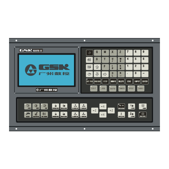
J O G PARAMETER OFFSET DIAGNOSIS A U TO Introduction of GSK 928TEⅡ Turning CNC System operator panel as follows: LCD display: CNC man-machine dialogue interface. Resolution 480×240 lattice TFT color LCD display. Digit key: input all kind: Input all kinds of data(0-9). - Page 15 Operation Chapter Two System Operator Panel REDUCING FEEDATE OVERRIDE: Reduce feedrate override in JOG mode and G01 feedrate override in AUTO mode. X PROGRAM REFERENCE POINT(PROGRAM ZERO) RETURN : It is valid in JOG/AUTO mode. Z PROGRAM REFERENCE POINT (PROGRAM ZERO) RETURN : It is valid in JOG/AUTO mode.
- Page 16 GSK928TEⅡ Turning CNC System User Manual OFFSET mode DIAGNOSIS mode 3.5 Edit/state key Switch the input method in EDIT mode—- INSERT/REWRITE . Delete a number, a letter, a block or a whole program. Cancel the current input all kind of data or escape from the current operation state. Input all kind of data or select the required or run program or create a new part program.
- Page 17 Operation Chapter Two System Operator Panel Start and pause programs in AUTO mode. CYCLE START: Start to run programs in AUTO mode. FEED HOLD: Motor reduces to pause in JOG or AUTO mode. 3.7 Manual axis control key The selected axis and its direction in JOG mode: X axis moves negatively in JOG mode.
- Page 18 GSK928TEⅡ Turning CNC System User Manual Spindle rotates counterclockwise. Spindle rotation (CCW) Spindle stops. Spindle stop Spindle rotates clockwise. Spindle rotation (CW) Cooling ON/OFF Cooling control Select the speed of each gear when the machine is equipped Spindle gear shifting with multi-gear (up to 16 gears) spindle motor and control loops.
-
Page 19: Chapter Four System Operation
2. Connect with the power switch of the CNC system. Press and the system displays GSK mark and caption, at the time, the system displays the software and hardware version number, delivery date by pressing other keys persistently except for the reset key. -
Page 20: Cnc System Operating Mode
GSK928TEⅡ Turning CNC System User Manual run efficiently and stably. Fig. 1 System initialization display 4.2 CNC System Operating Mode GSK928TEII CNC System uses operating mode keys to select directly the operating mode, which is helpful to directly change operating modes, easy, convenient and direct operations. After GSK928TE CNC System is switched on, the dynamic display window i s as Fig. - Page 21 GSK928TEⅡ Turning CNC System User Manual Fig. 2 EDIT operating mode Edit keys in EDIT mode cursor UP key The cursor moves to the first character behind the block number of the upper block when the key is pressed once. The key being pressed down, the cursor sequentially moves up till the first block of block or the key is released.
- Page 22 GSK928TEⅡ Turning CNC System User Manual DRY Run key (5) The cursor moves to the head of block or the head of first word of this block by pressing continuously. STEP/JOG mode (6) The cursor moves to the behind of the last character of this block. REWRITE key (7)...
- Page 23 GSK928TEⅡ Turning CNC System User Manual Fig. 3 Searching a part program catalog / creating, selecting and deleting part programs Most %00~%99 program names are displayed in each screen. When part programs in memory area are over 100, they are displayed by paging. Press to display the program number list of next page and press to display again the program number list of first page till the...
- Page 24 GSK928TEⅡ Turning CNC System User Manual Fig. 4 Inputting a program number Fig. 5 Creating a new part program 4.3.2.2 Deleting a Part Program (1) Press in the state of catalog search of part program. (2) Input the required deleted program number by keyboard. (3) Press and the system will display Confirm ?.
- Page 25 GSK928TEⅡ Turning CNC System User Manual Fig. 6 Deleting a part program 4.3.2.3 Selecting a Part Program (1) Press in the state of catalog search of part program. (2) Input the required selected program number by keyboard. (3) Press (4) The part program is selected completely and the system displays its content to enter EDIT mode.
- Page 26 GSK928TEⅡ Turning CNC System User Manual 4.3.2.4 Outputting a Part Program Output part programs from CNC system internal memory to the external computer. 1. Connect the communication cable between CNC system and the computer when power off. 1. After CNC powers on, select EDIT mode. 2.
- Page 27 GSK928TEⅡ Turning CNC System User Manual name to save. If the sent program name is the same as one in CNC system, the system cannot display the program name content of the sent program name, and will display it if the old one is deleted.
- Page 28 GSK928TEⅡ Turning CNC System User Manual 4.3.2.8 Copying a Part Program Copy the content of current program to another new one and consider it as the current one. Press , and the system displays ⑴ put a program name which does not exist in the program name list, and press ⑵...
- Page 29 GSK928TEⅡ Turning CNC System User Manual Fig. 8 automatically creating block number and inputting program content 4.3.3.2 Inputting Content of Program EDIT mode of the CNC system is employed with the full screen. Inputting content of program is executed in EDIT mode. (1) Create a new program according to the creating method of new part program.
- Page 30 GSK928TEⅡ Turning CNC System User Manual (1) Press to move the cursor to the first one of two blocks. (2) Press to move the cursor to the behind of last character, or press to move directly the cursor to the behind of last character. (3) Press , and the system will generate a new block number between two blocks (the increment of sequence number is 1/4 integral value of P23, and if there is not enough, the...
- Page 31 GSK928TEⅡ Turning CNC System User Manual Fig 9. Generating a new block number after is pressed Fig. 10 Input and end the insertion 4.3.3.4 Deleting a Block Delete all content in one block (including block number). (1) Press to move the cursor to the required block. (2) Press to move the cursor to the under of the address of required block.
- Page 32 GSK928TEⅡ Turning CNC System User Manual inserting position. (3) Input the inserting content. (4) Insert the content before the address character pointed by the cursor. between X and 0 of N0020 G0 X0.0 Z0.0. Move the cursor to Example:Insert 1 the under of O behind of X ,and input 1 .
-
Page 33: Manual Mode
GSK928TEⅡ Turning CNC System User Manual The end is :N0020 G0 U 0.0 Z0.0. 4.3.3.8 Skipping a Block before the block number N of block, and the system will skip the block to execute the next one when executing the program. (1) Switch to INSERT mode. - Page 34 GSK928TEⅡ Turning CNC System User Manual traverse along the selected axis and direction. The slider will stop once the key is released. The traverse speed will be executed according to the selected rapid traverse speed or feedrate. Meanings of manual feed direction keys in JOG mode are as follows: X negative key X positive key Z negative key...
- Page 35 GSK928TEⅡ Turning CNC System User Manual Its step width is divided into 6 grades: 0.001 0.01 0.1 1.0 10.0 50.0 Press to select each step width. The step width degrades one grade if it is pressed once. It returns to the first grade after the last one is selected. Note 1: In STEP mode, press to stop slider traversing.
- Page 36 GSK928TEⅡ Turning CNC System User Manual Note 1: The MPG speed of should be lower than 5 rev/s, otherwise the motor still moves even if the MPG has stopped, which causes the moving distance does not correspond with the scale. Note 2: In MPG mode, all the functions related to the axis moving including JOG, zero return, incremental/absolute movement are invalid, but S, M, T and other auxiliary functions are valid.
- Page 37 GSK928TEⅡ Turning CNC System User Manual 1000 1260 4.4.5 Manual Rapid Traverse Speed/Feedrate Select the rapid traverse speed/feedrate in JOG feed mode. The rapid traverse speed can be selected by rapid traverse override divided into four gears 25%, 50%, 75%, 100%. The actual feedrate is defined by the rapid traverse speed and the rapid traverse override: X actual rapid traverse speed = P06 ×rapid traverse override Z actual rapid traverse speed = P05 ×rapid traverse override...
- Page 38 GSK928TEⅡ Turning CNC System User Manual 4.4.6 Creating a Workpiece Coordinate GSK928TE CNC system uses a floating workpiece coordinate which is the benchmark of Ⅱ toolsetting and related dimension. After the system is installed, the workpiece coordinate must be created firstly. When the actual position is inconsistent with that of the workpiece coordinate, the coordinate is created again as follows: (1)...
- Page 39 GSK928TEⅡ Turning CNC System User Manual reference point return (G26, G27, G29) or pressing the reference point return keys, at the moment, cancel the tool compensation and the system offset. There are two methods to modify the tool offset values(absolute input and incremental input) as follows: The first method: Move the cursor to the required tool offset number, press to display...
- Page 40 GSK928TEⅡ Turning CNC System User Manual Example:X moves negatively 15.8 mm from the current position as follows: Press U – 1 5 . 8 , and the system displays Run ?; press , and X moves negatively 15.8 mm. 4.4.9 Absolute Movement of Coordinate Axis In “Manual”...
- Page 41 GSK928TEⅡ Turning CNC System User Manual M11 M32 M24. Omit it if the first digit of M code is zero. The function is the same that in AUTO mode. For the explanations of M codes, see Programming. When MDI is error, the system prompts “DATA INVALID” and disappears by pressing .
- Page 42 GSK928TEⅡ Turning CNC System User Manual 2) In level control mode,M3, M4, M5, MSP output time sequence M3 or M4 T1:In pulse control mode,M3, M4, M5 signal duration is set by P15; T2:Setting value: 0.2s; T3:The output duration of spindle braking signal MSP is set by P16. 4.4.12 Manual Spindle Speed Control For the machine with the multi-gear motor, press or directly input the spindle speed code...
- Page 43 GSK928TEⅡ Turning CNC System User Manual Input orderly S , and S8 signal is output with the displaying Prg. Speed S08. Besides, press to change the spindle speed. If it is pressed once, the spindle speed is output circularly S1, S2, S3, S4,(P11 bit 4=0) or S0~S15 ((P11 bit 4=1). The spindle speed switches from S2 to S1 by pressing three times when the spindle speed only has two-gear.
- Page 44 GSK928TEⅡ Turning CNC System User Manual Note 1: The spindle speed is controlled by P12 Bit0. When Bit0=0: it is the multi-gear control; when Bit0=1: it is 0-10V analog voltage control. Note 2: When P12 Bit0=1, P11 Bit4 is invalid, i.e. the spindle is always controlled by the converter. At the moment, the output point S1, S2, S3, S4 is controlled by M41, M42, M43, and the corresponding output point cannot be controlled by the spindle gear shifting key.
- Page 45 GSK928TEⅡ Turning CNC System User Manual Example: Input T22: switching to No. 2 tool and executing its compensation. Input T31: switching to No. 3 tool and executing its compensation. Input T40: switching to No. 4 tool and executing its compensation. Input T00: canceling the tool change and the tool compensation.
- Page 46 GSK928TEⅡ Turning CNC System User Manual offset. 3. Select any one tool after the workpiece is fixed on the machine (usually, the tool is the first one used in machining). 4. Start the spindle with the proper speed. Traverse the tool to cut a little sidestep on the workpiece in “Manual”...
- Page 47 GSK928TEⅡ Turning CNC System User Manual needed to tune. Firstly, cancel the tool compensation (T00) or execute program reference point return (program home) when the tool compensation cannot be input or the counting data is wrong. Fixed point toolsetting mode: Select anyone tool (usually it is the first one used in machining) as a reference tool after installing the trial cutting workpiece on the machine.
- Page 48 GSK928TEⅡ Turning CNC System User Manual When the fixed point toolsetting is executed by hand, X tool offset value sign related to the tool number is changed, i.e. “+” is changed into “-”and“-”into “+”. 4.4.16 Manual Program Reference Point Return X, Z zero return (program zero return, machine zero return) operations must be executed at the same time.
- Page 49 GSK928TEⅡ Turning CNC System User Manual Z machine zero return Press to move Z positively to the machine zero at the selected rapid traverse speed. Operations of machine zero return with the machine zero signal (P12 Bit4=0) are as follows: 1.
- Page 50 GSK928TEⅡ Turning CNC System User Manual Bit4=1:the hydraulic chuck control signal uses the pulse control; its width is defined by the time of P15; Bit3=0:the hydraulic chuck needs to receive the in-position feedback signal; Bit3=1:the hydraulic chuck does not need to receive the in-position feedback signal. In outside chuck mode: After M10 is executed, the system outputs the chuck clamping signal from X 7.19 (the output pulse or the level signal is selected by the parameter) and the chuck clamping operation ends without needing the in-position feedback signal;...
- Page 51 GSK928TEⅡ Turning CNC System User Manual the system prompts “Spindle Ready Failure” to stop executing the next block; when executing M3 or M4 in the state of chuck releasing, the system prompts: “Chuck Ready Failure” to stop executing the next block. 4.4.19 Hydraulic Tailstock Control Function When P25 Bit0 is 1, the system has the hydraulic tailstock control function.
-
Page 52: Auto Mode
GSK928TEⅡ Turning CNC System User Manual 4.5 AUTO Mode In AUTO mode, CNC system executes the selected part programs orderly to machine the qualified workpiece. Press to enter AUTO mode. Select the dry run or the machining run; select the single block machining run or the continuous machining run in AUTO mode. - Page 53 GSK928TEⅡ Turning CNC System User Manual In DRY RUN mode, the slider does not traverse and other auxiliary function controls are invalid when programs run. Select block number Select the required block by pressing and start to run from the selected block by pressing Program run key Execute one block in Single mode and one operation in cycle commands by pressing the key.
- Page 54 GSK928TEⅡ Turning CNC System User Manual 2. After selecting the required block and pressing , the system prompts “Run?” to wait the next execution. 3. After pressing with “Run ?”on the screen, the system will automatically traverse to the starting point of selected block and start to execute the block. The system escapes from the selected block and return to the first block after pressing Press to execute the program from the selected block.
- Page 55 GSK928TEⅡ Turning CNC System User Manual 4.5.2.4 Dry Run and Machining Run After editing a part program, ensure the coordinate data on the screen is the same that of the actual one and the relationship between blocks is right to avoid the bad effect caused by inputting mistake program data.
- Page 56 GSK928TEⅡ Turning CNC System User Manual Press to switch between the coordinates and the graphics display in AUTO mode. After switching from the coordinates display to the graphics display in run, the path of tool nose after switching is only displayed, the one before switching cannot be displayed. 4.5.3.2 Graphics Display in a Program Running When there is no program to run in AUTO mode, press to display the planar solid in...
- Page 57 GSK928TEⅡ Turning CNC System User Manual Fig. 20 Data definition of graphics display Length(LEN.): Total length of blank Unit:mm Diameter(DIA.): Max. outer diameter of blank Unit:mm Offset(OFFS.): Z offset between the programmed benchmark point and the starting point of blank, X programmed benchmark point is the center line of blank. Unit: mm Example:length of blank:100mm End face 2 End face 1...
- Page 58 GSK928TEⅡ Turning CNC System User Manual the cursor points to Scale . The scale is defined by the system: 4:1, 3:1, 2:1, 1:1, 1:2, 1:3 and 1:4. User can select the proper scale to realize the best view effect. After rewriting the data, press to return to AUTO mode, the system updates the displaying range of blank according to the set display data in the graphics display mode.
- Page 59 GSK928TEⅡ Turning CNC System User Manual Actual feedrate = F×feedrate override It has 16 gears from 0%-150% (increment of 10%). All the feedrate commands are controlled by feedrate override. When the feedrate override is 0, the programs stop. Rapid traverse override tune the rapid traverse speed (G00) X actual rapid traverse speed = P05×rapid traverse override Z actual rapid traverse speed = P06×rapid traverse override...
- Page 60 GSK928TEⅡ Turning CNC System User Manual : The operation of single block stop is valid when the program is running in AUTO Note (Continuous) Run mode, and pressing key is invalid when the program is running in AUTO Single mode. When executing the canned cycle commands, the operation of single block stop is valid after finishing each step of the canned cycle.
- Page 61 GSK928TEⅡ Turning CNC System User Manual display window of offset modification to execute the offset modification in PAUSE mode. ● Cooling ON/OFF Press to switch cooling ON/OFF. When the cooling is ON, the system displays Cooling ON and LED is ON in the top right corner; when the cooling is OFF, the system displays Cooling OFF on the screen and LED is OFF in the top right corner.
- Page 62 GSK928TEⅡ Turning CNC System User Manual Press the correspond keys to control the spindle starting/stopping when the feed hold knob is placed to the position 1 and 2; but the spindle cannot be started when it is placed to the position In AUTO Single mode When the knob is placed to the position 1, all commands run normally;...
-
Page 63: Parameter Setting
GSK928TEⅡ Turning CNC System User Manual 4.6 Parameter Setting There are 25 parameters ( P01~P25) in this system. Each parameter is defined to execute a certain operating mode of the CNC system and the machine, and so some parameters must be modified when the machine is installed and tuned. - Page 64 GSK928TEⅡ Turning CNC System User Manual traverse override. Unit: mm/min 4.6.1.4 P06—X Rapid Traverse Speed P06 defines X rapid traverse speed in “Manual” mode and G00. The actual rapid traverse speed is also controlled by the rapid traverse override. X actual rapid traverse speed = P05* rapid traverse override.
- Page 65 GSK928TEⅡ Turning CNC System User Manual Bit7 Bit6 Bit 5 Bit 4 Bit 3 Bit 2 Bit 1 Bit 0 Bit 7 0 in MPG mode, 0.1mm override is valid. 1 in MPG mode, 0.1mm override is invalid, enter the menu after the system has been ON for 15s.
- Page 66 GSK928TEⅡ Turning CNC System User Manual alarms ” Z drive unit alarm input signal(Zalm)being LOW, the system alarm “ Z drive alarms ” Bit 5 0 X drive unit alarm input signal(Xalm)being HIGH, the system alarm “ X drive alarms ” X drive unit alarm input signal(Xalm)being LOW, the system alarm “...
- Page 67 GSK928TEⅡ Turning CNC System User Manual P16 defines the duration of brake signal when the brake signal of spindle is output. Unit: 0.1 second. 4.6.1.13 P17—Z Lowest Initial Speed P17 defines Z lowest initial speed with G00 or in “Manual” mode. Unit: mm/min. When Z actual speed n is lower than the value of P17, there is no course of Z acceleration/deceleration The value of P17 must be tuned to the proper one according to the actual load of machine.
- Page 68 GSK928TEⅡ Turning CNC System User Manual Bit 7 Bit 6 Bit 5 Bit 4 Bit 3 Bit 2 Bit 1 Bit 0 Bit 7 0 decelerating to zero is valid. 1 not decelerating to zero is valid. The parameter decides that the connection method of two commands when the system executes continuously the block in AUTO mode.
- Page 69 GSK928TEⅡ Turning CNC System User Manual The parameter specifies which method is used when the system runs upon the hard limit. When it is set to 0, the system alarms and the motion axis decelerates because the system runs upon the hard limit; when it is set to 1, the system alarms and the motion axis stops suddenly and the coordinates are not same that of the actual position because the system runs upon the hard limit.
- Page 70 GSK928TEⅡ Turning CNC System User Manual Definition Unit Initial value Range Z positive limit value 8000.000 0~8000.000 -8000.000~0 Z negative limit value -8000.000 X positive limit value 8000.000 0~8000.000 -8000.000~0 X negative limit value -8000.000 Z max. traverse speed 6000 8~15000 8~15000 X max.
- Page 71 GSK928TEⅡ Turning CNC System User Manual time). Press to display the highlight. Input the parameter by keyboard. Press to delete the wrong input value and input it again. ● Press to confirm the input. Example :rewrite the value of P05 to 4500 as Fig. 22. :...
- Page 72 GSK928TEⅡ Turning CNC System User Manual : The input is invalid and the parameter content will not be changed if the input exceeds Note 2 the specified range. : Press after inputting the data, and the input is invalid. Note 3 :...
- Page 73 GSK928TEⅡ Turning CNC System User Manual highlight with its definition in English below the screen. ③ Press to move the cursor right or left to select the different bit, and the definition of selected bit will be changed along. After pressing , if is pressed, the system escapes from the bit search but the ④...
-
Page 74: Tool Offset Setting Mode
GSK928TEⅡ Turning CNC System User Manual 4.7 Tool Offset Setting Mode This system can define 8 groups tool offset value ( T1~T8). Each group offset has two data in X, Z direction. The offset group amount automatically generated by manual toolsetting is the same as the used tool ones. -
Page 75: Diagnosis
GSK928TEⅡ Turning CNC System User Manual ● Press to confirm the input, and store it into the parameter area of current selected offset number. Incremental input of offset data ● Select the offset setting mode. ● Press to move the cursor in highlight to the offset number to be modified (the selected offset number is displayed under the screen at the same time when moving the cursor). - Page 76 GSK928TEⅡ Turning CNC System User Manual Signal name Input interface diagnosis Z drive unit alarm X drive unit alarm No. 2 user input No. 1 user input X, Z negative travel limit X, Z positive travel limit Z zero X zero G31 check skip Input 2:...
- Page 77 GSK928TEⅡ Turning CNC System User Manual Signal name Output interface diagnosis Tool post CCW Tool post CW Spindle CW Spindle CCW Spindle stop Cooling ON M09/M79 Cooling OFF Spindle brake Alarm lamp red Output 2: Signal name Output interface diagnosis Workpiece clamped No.
- Page 78 GSK928TEⅡ Turning CNC System User Manual automatically. Press , the system starts to detect and display the spindle encoder lines. The course of detection will be circularly executed at the time before pressing the other keys to escape from the detection. Automatic detecting function of spindle encoder lines When “Diagnosis spindle encoder”...
-
Page 79: Alarm Of Emergency Stop And Overtravel
GSK928TEⅡ Turning CNC System User Manual 4.9 Alarm of Emergency Stop and Overtravel There is an integrated safeguard in this GSK928TE II CNC System to guard the operator’s safety and protect the machine from being damaged. 4.9.1 Emergency Stop There is an input terminal of external emergency stop in the input interface. User should connect Normally-closed contact of red mushroom emergency stop switch on the operator panel with the input terminal of emergency stop. -
Page 80: Drive Unit Switch Control
GSK928TEⅡ Turning CNC System User Manual 4.9.4 Other Alarms When there are other alarms, the system will prompt in English on the screen. Please deal with them correspondingly according to the prompt and the troubleshooting in the manual. 4.10 Drive Unit Switch Control In all non-running states, after pressing continuously twice, the drive unit is closed and the motor is released. -
Page 81: Programming
GSK928TEⅡ Turning CNC System User Manual Programming Chapter 1 Programming Fundamentals The automatic machining of CNC machine is the course of edited part programs automatically running. The programming is defined that the drawing and the technology of machining workpiece are described with CNC language and are edited to the part programs. Here describes the definition of command and the programming mode of CNC part programs. - Page 82 GSK928TEⅡ Turning CNC System User Manual system. For X axis, the system adopts the diameter programming (the dimension and the parameter in X direction are described in diameter). 1.3.1 Absolute Coordinate Values The absolute coordinate value is the distance to the coordinate origin, i.e. it is the coordinate value of the tool traversing to the end point as Fig.
-
Page 83: Workpiece Coordinate System
GSK928TEⅡ Turning CNC System User Manual applied, but the X ,U or Z ,W cannot be applied. For example, traverse the tool from A point to B point as Fig. 3, X axis is applied with the absolute coordinates and Z axis with the incremental coordinates as: X 5 0 W -4 0. -
Page 84: Chapter 2 Program Structure
GSK928TEⅡ Turning CNC System User Manual Chapter 2 Program Structure CNC command set edited according to the requirement of machine moving is named as program. According to the sequence of command, the tool traverses along the straight line and the circular arc, or the spindle starts/stops, cooling is ON/OFF. -
Page 85: Block Number
Programming Chapter Three Commands and Functions The invalid 0 of digital character string can be omitted. The leading zero of command can be omitted. For example: G00 can be written to G0. The positive sign can be omitted, but the negative sign must not be omitted. 2.3 Block Number A block number consists of the letter N and the following 4-digit integer. -
Page 86: Chapter 3 Commands And Their Functions
GSK928TEⅡ Turning CNC System User Manual Chapter 3 Commands and their Functions Here describes the function and the specification of all commands of GSK928TE CNC System. Ⅱ 3.1 G commands — Preparatory Function G commands are defined as the run mode of machine, composed of the character G and the following 2-digit as the following table. - Page 87 Programming Chapter Three Commands and Functions The tool rapid traverses to the specified position with G00. G00 X(U) Z(W) are the coordinate value of the specified point. Fig. 4 G00 rapid traverse Example:Traverse from A to B with G00 as Fig. 4: Absolute programming: N0010 G00 X18 Z0 ;...
- Page 88 GSK928TEⅡ Turning CNC System User Manual Fig. 5 G01 linear interpolation Traverse from A to B with G01 and its speed is 150 mm/min as Fig. 5. Absolute programming: N0100 G01 X45 Z-35 F150 ; Incremental programming: N0100 G01 U25 W-35 F150 ; G01 can define separately the motion of X or Z.
- Page 89 Programming Chapter Three Commands and Functions Fig. 6a G2/G03 Z negative direction Fig. 6b G02/G03 Z positive direction X, Z or U, W defines the end point of arc. It can be described with the absolute or the incremental coordinates. The incremental coordinate is the distance from the starting point to the end point of arc.
- Page 90 GSK928TEⅡ Turning CNC System User Manual N0110 G02 X60 Z40 I0 K-20 F100 ;Circle center programming. N0110 G02 X60 Z40 R20 F100 ;Radius programming or N0110 G02 U40 W-20 I0 K-20 F100 ; N0110 G02 U40 W-20 R20 F100 ; The feedrate of the counterclockwise interpolation from A to B is 100 mm/min.
- Page 91 Programming Chapter Three Commands and Functions I——it is X moving distance(diameter value) when executing the thread run-out. Unit: mm. When there is K and I is omitted, the system defaults I=2×K( 45° thread run-out) and I is not negative. D ——rotary machining depth.(unit: mm ) When G04 is with others, D is the delay time.
- Page 92 GSK928TEⅡ Turning CNC System User Manual G33 W-40 K3 I5 D4.4 P2; End point (Z60,X100.60) 3. G33 axial taper thread:(≤45°,U/2≤W) as Fig. 9-3 Starting point End point U sign decides the direction of the thread run-out; K sign is invalid; the machining cannot execute the rotary machining;...
- Page 93 Programming Chapter Three Commands and Functions Starting point End point K sign decide the direction of the thread run-out; when K is omitted, there is no the thread run-out; when there is no I, I=K/2. Example:G00 Z100 X20; G33 K3 I1.6 U20.7 P2; End point (Z101.60,X40.70) 6.
- Page 94 GSK928TEⅡ Turning CNC System User Manual the spindle encoder, and so the cutting points on the circle of machining workpiece are the same when repeating the thread cutting many times, the spindle speed must not be changed at the same time, otherwise there is the error of thread cutting. The feedrate of thread cutting and the spindle speed are comfortable.
- Page 95 Programming Chapter Three Commands and Functions Example: G33 W-20 P3;the system detects 1-turn signal when the thread cutting is executed. G33 W-30 P2; the system does not detect 1-turn signal when the thread cutting is executed. 3.1.5 G32 — Z Tapping Cycle Command format:G32 Z (W) P (E);...
- Page 96 GSK928TEⅡ Turning CNC System User Manual 3.1.6 G50 — Creating a Workpiece Coordinate System Command format: G50 X Z; G50 defines a coordinate system and confirms the current position of tool in the coordinate as X, Z coordinate value. The defined coordinate system by G50 is named as the workpiece coordinate system. The absolute coordinate in the following command must be in it after the workpiece coordinate system is set.
- Page 97 Programming Chapter Three Commands and Functions 3.1.7 G26 — Reference Point Return Command format:G26 ; The tool returns to the reference point( machining starting point) with G26, and the mode of the reference point return with G26 is the same that of G00. See Fig. 13: Fig.
- Page 98 GSK928TEⅡ Turning CNC System User Manual 3.1.9 G29 — Z Reference Point Return Command format:G29 ; After X returns to the reference point with G27 at the rapidest traverse speed controlled by the rapid traverse override, Z offsets of tool and system are cancelled. When X offset value is also 0, and the tool offset number is displayed to 0.
- Page 99 Programming Chapter Three Commands and Functions Do not execute the constant surface speed control in G96 if the system adopts the gear shifting spindle. Note 2: The constant surface speed control is valid only in AUTO mode and the system will automatically cancel the constant surface speed control after escaping from AUTO mode or resetting.
- Page 100 GSK928TEⅡ Turning CNC System User Manual When executing the taper surface cutting cycle, R sign is determined by the X from C to B. Rapid traverse Cutting feed Fig. 14 Inner/outer cylindrical (taper) surface turning cycle Relationships between the data behind U, W, R and the tool path are as follows: (1)U<0,W<0,R<0 (2)U<0,W<0,R>0 X from A to B is negative, so U<0;...
- Page 101 Programming Chapter Three Commands and Functions Example 1: Fig. 15a outer cylindrical surface: the first cutting feed= 5 mm, the second cutting feed= 2 mm, F=100 mm/min. N0010 G00 X47 Z62 ;rapidly position to A N0020 G90 X40 Z30 F100 ;cycle once A B C D A N0030 X35 ;the first tool infeed to cycle once A B1 C1 D A...
- Page 102 GSK928TEⅡ Turning CNC System User Manual Starting point of cutti ng E nd po in t o f cutting R ap id l y return t o sta rtin g p oint to exec ute the cycle c utting P is positive; K sign decodes the direction of the thread run-out; when K is omitted, there is no the thread run-out;...
- Page 103 Programming Chapter Three Commands and Functions Sta rting point of cutti ng End po int o f cutting P is negative; R sign decides the direction of the thread run-out; K sign is invalid; there is no the rotary machining; when there is no I, I=K/2. Example:G00 Z100 X10 G92 W-10 U60 R10 K3 I1.5 P-2 5.
- Page 104 GSK928TEⅡ Turning CNC System User Manual Example:G00 Z100 X10 G33 W-30 U80 K5 I2.5 D3 P-2 Starting point o f cuttin g End point o f cutting It is necessary to execute the cutting feed many times, at the moment, only rewrite X coordinate value of end point of cutting feed (or the increment value compared to the starting point).
- Page 105 Programming Chapter Three Commands and Functions (1)R<0 (2)R>0 Diameter difference between starting point B and end point C is Diameter difference between starting point B and end point C is negative, so R<0 positive, so R>0 (3)R=0,K>0 (4)R=0,K<0 K>0,the thread run-out is the positive of X. K<0,the thread run-out is the negative of X.
- Page 106 GSK928TEⅡ Turning CNC System User Manual The tool is still on A after executing the above-mentioned blocks. Example 2: Outer taper thread as Fig. 17 b (R1 : D=41.910, D2=40.431, D1=28.952, P=2.309, the valid length of thread is 19.1) N0010 G00 X45 Z5 ;rapidly position A N0020 M03 S600 ;spindle CW,600 rev/ min...
- Page 107 Programming Chapter Three Commands and Functions N0020 G94 X25 Z40 F80 ;the first cycle A B C D A N0030 Z35 ;tool infeed 5mm, the 2 cycle A B1 C1 D A N0040 Z33.5 ;tool infeed 1.5m, the 3 cycle A B2 C2 D A Example 2: Fig.
- Page 108 GSK928TEⅡ Turning CNC System User Manual X fro m B to C is n e g a tive , so U < 0; X fro m B to C is ne g a tive , so U < 0; X fro m A to B is n e ga tive , so W < 0; X fro m A to B is n e g a tive, so W <...
- Page 109 Programming Chapter Three Commands and Functions 1. Z feeds the distance I AT F speed. 1. Z retracts the distance K. 2. Z feeds the distance I+K at F speed. 3. Z repeats the above-mentioned steps 2 3 until feeding to B. ~...
- Page 110 GSK928TEⅡ Turning CNC System User Manual Cutting feed Rapid traverse Fig. 22 G74 cycle- deep hole drilling cycle (R≠0) 3.1.13.5 G75 — Grooving Cycle Command format:G75 X (U) Z (W) I K E F ;I / K is not negative value. X(U)Z(W)—end point coordinate of slot.
- Page 111 Programming Chapter Three Commands and Functions Fig. 24 grooving cycle: tool width= 5 mm,cutting feed once= 6 mm,retracting= 2mm once, offset= 5 mm once,F=150 mm/min. Fig. 24 Grooving cycle N0030 G0 X125 Z100 ;position to the starting point; N0040 G75 X80 Z35 I6 K2 E5 F150;grooving cycle. The width of tool is added to the end point coordinates.
- Page 112 GSK928TEⅡ Turning CNC System User Manual 2. Z cuts feed and its end point is defined automatically by the system. 3. X retracts the distance K at F speed. 4. Z rapidly retracts to the starting point. X feeds the distance I+K. 5.
- Page 113 Programming Chapter Three Commands and Functions N0030 G00 X83 ;X infeeds and approaches the workpiece N0040 G71 X0 I4 K2.5 L7 F60 ;define parameters of roughing cycle N0050 G01 Z145 ; N0060 X15 ; N0070 W-30 ; Define final path N0080 G02 X55 W-20 I0 K-20 (N0050-N0110)...
- Page 114 GSK928TEⅡ Turning CNC System User Manual final path. Note 3: Other cautions are the same those of G71. Fig. 27 G71 cutting Cutting as Fig. 27 : rod Φ82: cutting feed= 4 mm every time, retract=2.5 mm, F= 60mm/min N0000 G00 X180 Z50 ;position the starting point N0010 M3 S02 ;start the spindle, set to the speed 2 gear...
- Page 115 Programming Chapter Three Commands and Functions Cycle process: 1. G22 defines the starting of cycle body and L defines the cycle times. 2. Execute the cycle body program. 3. Cycle times L subtracts 1 when G80 cycle body ends. Execute the cycle body program again when L ≠0;...
- Page 116 GSK928TEⅡ Turning CNC System User Manual 3.1.16 G93 — System Offset Command format:G93 X (U) Z (W) ; X (U) -X offset value, U is the same that of X(the incremental coordinates and the absolute coordinates are the same). Z (W) -Z offset value, W is the same that of Z(the incremental coordinates and the absolute coordinates are the same).
- Page 117 Programming Chapter Three Commands and Functions G99 G01 X50,Z30 F0.2 ; G04 D2 ; G99 G01 X50,Z30 F0.2 ;...
-
Page 118: M Function -Miscellaneous Function
GSK928TEⅡ Turning CNC System User Manual 3.2 M function —Miscellaneous Function The M functions are used for the start/stop of machine and the run order of part program. M commands consist of address characters and the following 2-digit integer. All M functions of GSK928TEⅡ... - Page 119 Programming Chapter Three Commands and Functions 3.2.2 M02 —End of Program Command format: M02 End programs and return to the first block to wait. 3.2.3 M20 — End of Program and Machining Cycle Command format: M20 End programs and return to the first block to execute repeatedly with M 20, which is used for checking the system or the machine.
- Page 120 GSK928TEⅡ Turning CNC System User Manual M08, M09 can be set to the pulse or level mode. The pulse duration is defined by P15, and the mode of pulse or the level is determined by P12 Bit2. In the level mode, M09 output point outputs the level signal.
- Page 121 Programming Chapter Three Commands and Functions N0060 G01 U2 N0070 W-5 N0080 M99 N0090 M02 Does not execute directly N0060 but N0090 after executing N0050. 3.2.11 M98 M99 — Subprogram Call and Return Command format: M98 P**** L** ; P — block number of subprogram. It must be with 4-digit. L —...
- Page 122 GSK928TEⅡ Turning CNC System User Manual times, and then execute N0050,the program skips to N0130 at the moment and execute the following blocks. Method two :When executing N0040, call subprograms and execute N006 0-N0120 five times, and then execute blocks from N0050 to N007, and so the program ends. 3.2.12 M21 M22 M23 M24 —...
-
Page 123: S Function - Spindle Function
Programming Chapter Three Commands and Functions M91: check the state of No. 1 user. When the state is valid (input terminal connects with 0V), skip to the block specified by P, otherwise the next block is executed. M92: check the state of No. 1 user, when the state is invalid (input terminal cuts off 0V), skip to the block specified by P, otherwise the next block is executed. -
Page 124: T Function - Tool Function
GSK928TEⅡ Turning CNC System User Manual Command format: S **** ; ****is spindle speed . Unit: rev/min When the converter spindle is controlled by S function, and the corresponding highest speed with the output 10VDC is defined by P09, P10, P23 and the spindle gear control signal M41, M42, M43. -
Page 125: F Function - Feedrate Function
Programming Chapter Three Commands and Functions 3.4.1 Tool Offset Mode — Traverse the Slider of Machine P11 Bit6=0: the tool compensation mode is to traverse the slider of machine. In “Manual” mode, when executing ‘Tab’,execute the tool change of tool No.a, and then execute the tool compensation value b, at the moment, the slider actually traverses to the position which is the one by executing the compensation, and the system coordinates do not be changed. -
Page 126: Chapter Four Programming Rules
GSK928TEⅡ Turning CNC System User Manual Chapter Four Programming Rules 4.1 Some Commands in One Block It is defined that there are some commands in the same one block simultaneously, but only some commands in the same one block are as follows: G22, G80, G71, G72, G90, G94, M21, M22, M23, M24, M91, M92, M93, M94, M97, M98, M99 and so on. -
Page 127: Other Rules
Programming Chapter Four Programming Rules 4.3 Other Rules Without the repeat commands in a block The required data cannot be omitted in a block No.1 tool No.2 tool No.3 tool No.4 Have no the unrelated data with commands in a block When the first digit is zero in a command, it can be omitted. - Page 128 GSK928TEⅡ Turning CNC System User Manual N0120 G90 X56.5 Z35 F100 ; turn Φ45mm with cylindrical surface cycle command N0130 X52.5 ; tool infeed 4mm and cycle again N0140 X48.5 ; tool infeed 4mm and cycle again N0150 X45.5 ; tool infeed 3mm and cycle again N0155 G00 X45.5 ;...
- Page 129 Programming Chapter Four Programming Rules N0000 G00 X50 Z11 ; set a workpiece coordinate system N0010 M3 S2 ; start the spindle, set the spindle speed to No.2 gear N0020 M8 ; cooling ON N0030 T11 ; execute No. 1 tool change and execute its tool compensation N0040 G00 Z0 X35 ;...
- Page 130 GSK928TEⅡ Turning CNC System User Manual Fig. 35 Multiple threads cutting a(Metric multiple threads) : N0010 G00 X100 Z50 ;set a workpiece coordinate system N0020 M03 S600 ;Spindle rotates (CW) with 600 r/min N0030 T44 ;change No. 4 tool and execute its offset N0040 G00 X25 Z5 ;rapidly approach the workpiece N0050 G92 X19.5 Z-30 P4.5 L3 ;execute No.
- Page 131 Programming Chapter Four Programming Rules 1 45° 1 45° Blank appearance Reference point Fig. 36 Machining example N0000 G00 X150 Z250 ;set a workpice coordinate system N0010 M3 S01 ;start the spindle and set its speed to gear 1 N0020 M8 ;cooling ON N0030 T08 ;execute the tool compensation with machining allowance...
- Page 132 GSK928TEⅡ Turning CNC System User Manual N0240 W-22 ;finish outer Φ16 N0250 X37 ;finish the end face Φ40 N0260 X40 W-1.5 ;chamfer 1×45° N0270 W-61.5 ;finish outer Φ40 N0280 G02 X80 W-20 I0 K-20 ;finish convex circle N0290 G03 X120 W-20 I40 K0 ;finish concave circle N0300 G01 W-20 ;turn outer Φ120...
- Page 133 Programming Chapter Four Programming Rules Fig. 37 Machining drawing N0010 G00 X100 Z50 ;set a workpiece coordinate system N0020 M3 S600 ;spindle rotates(CW) with 600 rev/min N0030 T11 ;change No.1 tool and execute its offset N0040 M 8 ;cooling ON N0050 G00 X50 Z3 ;approach the workpiece N0060 G71 X0 I 3 K2 L 4 F50...
-
Page 134: Alarm List
GSK928TEⅡ Turning CNC System User Manual N0260 X43 Z-43 ;chamfer N0270 X30 ;traverse to X30 outer for finishing N0280 Z-50 ;turn outer Φ30 N0290 G00 X45 ;traverse to the chamfer position N0300 G01 Z-51 F50 N0310 X43 Z-50 ;chamfer N0320 G00 X46 ;position the cut point N0330 Z-62 N0340 G01 X42 Z--63 F50... - Page 135 Programming Chapter Four Programming Rules 4.5.1 Alarm Prompts in Programming Mode Alarm prompt Definition Troubleshooting REPEAT Repeat the same instruction in the block Delete the repeat one INSTRUCTION REPEAT Repeat the same parameter in the block Delete the repeat one PARAMETER INCOMPATIBLE Have two or many instructions which cannot be in the same...
- Page 136 GSK928TEⅡ Turning CNC System User Manual 4.5.2 Alarm Prompts in Manual, AUTO Mode Alarm prompt Definition Troubleshooting Cannot find the specified tool No. when Check the rotation tool post and NULL TOOL NO. executing the tool change the input interface X/Z negatively moves till the limit X/Z OVERTRAVEL X/Z positive travel switch is closed...
-
Page 137: Appendix 1 Gskrs232 Communication Use
Programming Appendix Appendix 1 GSKRS232 Communication Use 928TC series CNC, 928TE series CNC transmission specifications: 1. Select the transmission mode: The program has two transmission mode, separately used for 928TC series CNC, 928TE series CNC and 25T series. Firstly select “928TE/991 series” in the system selection menu when the program executes the transmission with 928TC series CNC, 928TE series CNC. - Page 138 GSK928TEⅡ Turning CNC System User Manual 2. Open the file illustration: Use the file open button to select the required sending file. Press the button and the system pops-up the file window box.
- Page 139 Programming Appendix Select the file in the file select box, and the file will display in the edit box of communication software as follows: At the time, edit files in the edit box of communication software.
- Page 140 GSK928TEⅡ Turning CNC System User Manual 3. Saving a file: Use the save file button to save the data in the edit box. Click SAVE FILE and the system pops-up a file save dialogue box,select the save position and file name to save the file to the computer.
- Page 141 Programming Appendix 4. Sending a file. Click the sending button and the software window become the unavailable state. At the time, CNC automatically the sending state after it starts. If CNC does not start within 2 minutes, the communication program pops-up the prompt dialogue box: CNC does not start and is needed to recover.
- Page 142 GSK928TEⅡ Turning CNC System User Manual CNC firstly executes the receiving, and also the communication software firstly executes the sending. When the sending is started, the progress degree of communication software has the corresponding display. When the sending is completed, the communication software pops-up a completion dialogue box.
- Page 143 Programming Appendix 5. Receiving a file The two transmission modes have the same order. i.e. we can firstly start CNC or communication software. After the receiving is clicked, CNC has no data within 2 minutes and automatically recovers, the receiving progress degree will be displayed. When the receiving is completed, a completion dialogue box pops-up.
- Page 144 GSK928TEⅡ Turning CNC System User Manual 6. Related transmission settings: Serial setting: the software supports USB serial line, and 1~255 serials. 7. Transmission rate setting: support 3 kinds of transmission rate, but 928 series and 25T only use 9600 transmission rate.
- Page 145 Programming Appendix 8. Transmission speed control: The transmission speed control is executed by the control bar in the under of the software as the follow figure: 9. Advanced protocol setting: general user need not use the function, it is for the maintenance and debugging personnel.
-
Page 146: Appendix 2 C5.1 Flash Chip Copy And Check
GSK928TEⅡ Turning CNC System User Manual Appendix 2 C5.1 FLASH Chip Copy and Check 1. FLASH Chip Copy Copy the content of the new software U6 to U7 1) When the system is turned off, the toggle switch is as Fig. 1, the chip with the new software is inserted into U6 socket. - Page 147 Programming Appendix 10) After the system is turned on, if it runs normally, FLASH chip is checked as the follow methods to check whether FLASH write is correct. If it wrong, you should check whether the write switch is correct. Copy the content of the software U7 to U6 When the system is turned off, the joggle switch is as Fig.
-
Page 148: Connection
GSK928TEⅡ Turning CNC System User Manual Connection Chapter One Interface 1.1 Interface Layout... -
Page 149: Total Frame
Connection Chapter One Interface Profile 1.2 Total Frame GSK928TEⅡ 回 机 Machine Z drive unit Spindle Power Converter Machine X drive unit Tool post encoder input signal output signal supply... -
Page 150: Total Connection Layout
GSK928TEⅡ Turning CNC System User Manual 1.3 Total Connection Layout Switching value Switching value Converter output input RS232 Encoder Tool post Drive unit Drive unit Motor Motor... -
Page 151: Chapter Two Interface Function
Connection Chapter Two Interface Function Chapter Two Interface Function 2.1 Specifications R S2 32 S p in d le To ol pos t Mot or I npu t Out put e n co d e r (1) X1 RS232 interface,DB9 male socket. (2)... -
Page 152: Interface Graph
GSK928TEⅡ Turning CNC System User Manual 2.2 Interface Graph X1 RS232(male socket) X6 input(male socket) +24V D E C X D E C Z +24V +24V +24V M P G (female socket) M91/M92 M93/M94 M3XZ2 M3XZ1 X3 Spindle encoder(male socket) P Z + X7 output(female socket) +24V... -
Page 153: Chapter Three Cnc Device Connection
Connection Chapter Three CNC Device Connection Chapter Three CNC Device Connection X1 Communication Interface GSK928TEⅡ CNC and the external PC(RS232 interface)or GSK928TEⅡ CNC(X1 interface) are connected by the communication interface(X1), and exchange or transmit the data. 3.1.1 X1 Signal P in Name Remark Direction... - Page 154 GSK928TEⅡ Turning CNC System User Manual CNC device CNC device Cable length<15m TXD 3 The communication cable length is less than 15m, otherwise, which will cause the skipping data distortion. To avoid RS232 interface being damaged by the static electricity, the shells of CNC and PC should be connected separately to the ground wire as follows: X 2 MPG Interface The external manual pulse generator (MPG) can be connected to GSK928TEⅡ...
-
Page 155: X3 Spindle Encoder Interface
Connection Chapter Three CNC Device Connection 3.2.1 Signal Pin No. Name Function 6:0V 1:+5V MPG pulse A + MPG pulse A - 2:MA+ 7:MB+ 8:MB- 3:MA- MPG pulse B + MPG pulse B + 3.2.2 Interface Graph 26LS32 CNC side 3.2.3 Connection Layout When the axis moving is controlled by MPG, the moving direction of MPG cannot be changed... - Page 156 GSK928TE Ⅱ Turning CNC System User Manual Pin No. Name Function 1:PA+ 6:PZ+ PA﹢ Encoder pulse A+ 2:0V 7:0V 3:+5V 8:PA- 4:PZ- PZ﹣ Encoder pulse Z- 9:PB+ PB﹣ Encoder pulse B- 5:PB- PZ﹢ Encoder pulse Z+ PA﹣ Encoder pulse A - PB﹢...
-
Page 157: X4 Tool Post Device Interface
Connection Chapter Three CNC Device Connection 3.3.4 Connection Layout S p in dle en coder < 1 5m sh ie ld cable C N C side The shield cable must be used between the system and the spindle encoder, and the shield must be connected with the shell of two-terminal socket. - Page 158 GSK928TE Ⅱ Turning CNC System User Manual Pin Name Remark Tool post (CCW) rotation to output signal 1:TL+ +24V 9:TL- 10:0V 2:+24 No.1 tool in-position signal 11:T2 3:T1 No.3 tool in-position signal 12:T4 4:T3 X zero input signal 13:Z0 5:X0 14:BKI1 24V power supply ground 6:0V...
-
Page 159: X5 Feed Drive Unit Interface
Connection Chapter Three CNC Device Connection Connecting: +24V +24V JZ(CCW) JF(CW) GSK 28TEⅡ T1(No.1 tool) Tool post controller T2(No. 2 tool) T3(No. 3 tool) T4(No. 4 tool) CNC side Machine side It is recommended that the tool post control line should be connected to CNC by the shield cable, and the shield and the shell of socket should be connected. -
Page 160: Pulse Signal
GSK928TE Ⅱ Turning CNC System User Manual 3.5.3 Equivalent circuit 3.5.3.1 Drive unit alarm signal TLP181 D rive unit CNC side 3.5.3.2 Enabling signal 3.5.3.3 Pulse signal 300Ω 26LS31 CNC side Drive unit side 3.5.4 GSK928TEⅡCNC and compound stepper motor drive unit connection... - Page 161 Connection Chapter Three CNC Device Connection Connection layout between GSK928TE ⅡCNC and GSK DY3 X connection layout: < m shield cable Single phase DY3 drive unit GSK928TE II Xpu+ AC220V Xpu- Xdir+ Dir+ Xdir- Dir- Xalm RDY1 RDY2 Metal Metal...
- Page 162 CNC system, the stepper drive unit and the stepper motor must be reliably connected with the earthing to avoid the motor stepper out because of the external interference. 3.5.5 Connecting ⅡCNC and the reaction stepper motor drive unit Connection layout between GSK928TE ⅡCNC and GSK DF3 X connection layout <...
- Page 163 Zpu- Zdir+ Zdir- /DIR FREE /FREE Zalm Alm.OUT OUT.COM Metal Metal shell shell Connection layout between GSK928TEⅡ CNC and GSK DF3: GSK928TEⅡ(X) DF3 drive unit Pulse(X+) Xpu+ Pulse (X-) Xpu- Direction (X+) Xdir+ Dir+ Direction (X-) Xdir- Dir- Enabling (X)
- Page 164 CNC system, the stepper drive unit and the stepper motor must be reliably connected with the earthing to avoid the motor stepping out because of the external interference. 3.5.6 Connecting GSK928TEⅡ CNC and AC Servo Drive Unit Connection layout between GSK928TEⅡ CNC and GSK DA98 AC servo drive unit X connection layout <...
- Page 165 Connection Chapter Three CNC Device Connection Connection layout between GSK928TE ⅡCNC and GSK DA98 AC servo drive unit GSK928TEⅡ(X) DA98 drive unit Pulse (X+) Xpu+ PULS Pluse (X-) Xpu- /PULS Direction (X+) Xdir+ SIGN Direction (X-) Xdir- /SIGN Enabling (X) +24V...
- Page 166 GSK928TE Ⅱ Turning CNC System User Manual X connection layout < Three- phase AC220V MINAS V GSK928TE II Xpu+ PULS1 Xpu- PULSZ Xdir+ SIGN1 Xdir- SIGN2 SRV-ON +24V COM+ Xalm CCWL COM- Metal shell Metal shell 23 CWL Z connection layout <...
- Page 167 Connection Chapter Three CNC Device Connection 3.5.8 Connecting GSK928TEⅡ CNC and Japanese Yaskawa Drive Unit X connection layout < Three- phase AC220V GSK928TE II Yaskawa drive unit Xpu+ PULS+ Xpu- PULS- Xdir+ SIGN+ Xdir- SIGN- /S-ON +24V +24V Xalm AlM+...
-
Page 168: Switching Value Input Interface
GSK928TE Ⅱ Turning CNC System User Manual 3.6 X Switching Value Input Interface GSK928TEⅡ CNC has 16 channels switching value input used with the photoelectric isolation. 3.6.1 Signal Pin No. Name Function 14:ST 1:+24 Stop 2:SP 15:ESP 3:0V Hydraulic chuck pedal switch 16:0V a input 4:SHL... - Page 169 Connection Chapter Three CNC Device Connection 3.6.2 Technology specification ● Photoelectric couple technology with max. isolation voltage 2500VRMS ● Supply voltage 24V 3.6.3 The normally open contact of mechanical contact switch or the electric proximity switch without the contact( the contact is proximal, it is the LOW) are used for DecX ,DecZ, -XZL, +XZL, X0, Z0, M91, M93, SHL, M3XZ1, M3XZ2.
-
Page 170: X7 Switching Value Output
GSK928TE Ⅱ Turning CNC System User Manual Connection example: : Note 1. When the signal is valid, the slider reaches the machine home or the machine table touches the limit switch. 2. When the transistor of electric switch is conducted, the output voltage is within 1V; when it is cut off, the output voltage exceeds 23V. - Page 171 Connection Chapter Three CNC Device Connection 3.7.2 Technology Specifications ● Photoelectric hookup technology with max. isolation voltage 2500VRMS ● Supply voltage: 24V. 3.7.3 Connection Method Connection Layout LM358 10Ω CNC side Machine side 1)CNC outputs the signal to control the relative operation of machine, its direction:CNC machine.
-
Page 172: X7 Spindle Converter Interface
GSK928TE Ⅱ Turning CNC System User Manual b) Level control mode: output sequence of M3, M4, M5, MSP as follows: M3 or M4 Note:T1:In the pulse control mode, the output duration of M3, M4, M5 is defined by P15; T2:Fixed value :0.2s; T3:The output duration of spindle braking signal MSP is defined by P16. - Page 173 Connection Chapter Three CNC Device Connection 3.8.1 Signal Pin No. Name Function Spindle speed 1/spindle low S1/M41 gear 1:+24 14:+24V Spindle speed spindle S2/M42 medium gear 2:+24V 15:0V Spindle speed 3/spindle high S3/M43 3:S1/M41 16:M21/M22/M79 gear Spindle speed 4 4:S2/M42 17:M23/M24/M78 Spindle brake 18:M11...
- Page 174 GSK928TE Ⅱ Turning CNC System User Manual 3.8.4 Interface Method of Analog Voltage LM358 10Ω CNC side Machine side The system is connected with the converter by the shield cable.
-
Page 175: Appendix 1 Gsk928Teⅱ Tool Post Controller Circuit Diagram
Appendix Connection Appendix 1 GSK928TEⅡ Tool post Controller Circuit Diagram D1 D2 D3 D4 D5 D6 D7 D8... -
Page 176: Appendix 2 Interface Circuit Diagram
GSK928TE Ⅱ Turning CNC System User Manual Appendix 2 Interface Circuit Diagram Interface circuit diagram 1 R100 O100 R101 O101 R102 O102 R116 O116 M3XZ2 R103 O103 R117 O117 M3XZ1 R104 O104 SALM R118 O118 R105 O105 R119 O119 R106 O106 DECX R120... - Page 177 Appendix Connection Interface circuit diagram 2 DO20 BKO0 O200 O216 M21/M22 DO21 BKO1 O201 O217 O202 24VGND M23/M24 O203 O204 M32/M33 O205 O206 M10/M11 24VGND O207 M21/M22 DO10 M23/M24 O208 M32/M33 DO11 M10/M11 O209 DO12 O210 DO13 BRAKE 24VGND O211 D4.BAKIN DO14 SALM...
- Page 178 GSK928TE Ⅱ Turning CNC System User Manual Interface circuit diagram 3 O300 XSON IO5V C312 IO5V C313 24VGND O301 IO5V C314 ZSON IO5V R322 24VGND IO5V R323 R332 IO5V R324 R333 IO5V R325 U300 IO5V R326 R308 IO5V R309 R327 R310 IO5V R311...
-
Page 179: Appendix 3 Machine Zero Return Mode
Appendix Connection Appendix 3 Machine Zero Return Mode... - Page 180 GSK928TE Ⅱ Turning CNC System User Manual...
- Page 181 Appendix Connection Appendix 4 External Control Connection Layout M P G E l e c t r i c a l a p p a r a t u s l o g i c a l d e v i c e F o r w a r d / b a c k w a r d c o n t r o l t e r m i n a l A n a l o g v o l t a g e...
-
Page 182: Appendix 5 Gsk928Teⅱ Integrated Wiring Table
GSK928TE Ⅱ Turning CNC System User Manual Appendix 5 GSK928TEⅡ Integrated Wiring Table 1. Machine control signal X6 Input signal Signal Pin No. Definition name Stop Hydraulic chuck pedal DecZ Deceleration signal of Z reference point return +24V X negative limit Z negative limit M93/M94 No. - Page 183 Appendix Connection X7 Output signal Pin No. Name Definition S1/M41 Spindle speed 1/spindle low gear S2/M42 Spindle sped 2/spindle medium gear S3/M43 Spindle seed 3/spindle high gear Spindle speed Spindle brake COOLING ON Spindle rotation9CCW) Hydraulic tailstock pedal signal input Converter control voltage M21/M22/M79 No.1 user output/tailstock backward...
- Page 184 GSK928TE Ⅱ Turning CNC System User Manual Pin No. Signal Definition Tool post(CCW) rotationrotaion to output signal +24V No.1 tool in-position signal No.3 tool in-position signal X zero input signal BKI2 Standby input 2 BKO2 Standby ouput 2 Tool post(CW) rotation to output siignal No.2 tool in-position signal No.4 tool in-position signal Z zero input signal...
- Page 185 Appendix Connection J3 1 AC220V J3 2...
-
Page 186: Appendix 6 Appearance Installation Dimension Of Gsk928Teⅱ Turning Cnc System
GSK928TE Ⅱ Turning CNC System User Manual Appendix 6 Appearance Installation Dimension of GSK928TEⅡ Turning CNC System... - Page 187 Add: No.52, 1 Street, Luochong North Road, Luochongwei, Guangzhou, 510165, China Website: http://www.gsk.com.cn E-mail: sale1@gsk.com.cn Tel: 86-20-81796410/81797922 Fax: 86-20-81993683 All specifications and designs are subject to change without notice. April 2009/Edition 3 Software version: V6.0 April 2009/Printing 2...
Need help?
Do you have a question about the GSK928TE II and is the answer not in the manual?
Questions and answers