Table of Contents
Advertisement
Quick Links
ENGINEERING COMPANY INC.
51 Winthrop Road
Chester, Connecticut 06412-0684
Phone: (860) 526-9504
Fax: (860) 526-4078
Internet: www.whelen.com
Sales e-mail: autosale@whelen.com
Canadian Sales e-mail: autocan@whelen.com
Customer Service e-mail: custserv@whelen.com
DANGER!
Sirens produces extremely loud emergency warning tones! Exposure to these
tones without proper and adequate hearing protection, could cause ear damage and/or hearing
loss! The Occupational Safety & Health Administration (www.osha.gov) provides information
necessary to determine safe exposure times in Occupational Noise Exposure Section 1910.95.
Until you have determined the safe exposure times for your specific application, operators and
anyone else in the immediate vicinity should be required to wear an approved hearing protection
device. FAILURE TO FOLLOW THIS RECOMMENDATION COULD CAUSE HEARING LOSS!
Safety First
This document provides all the necessary information to allow your Whelen product to be properly and safely installed.
Before beginning the installation and/or operation of your new product, the installation technician and operator must
read this manual completely. Important information is contained herein that could prevent serious injury or damage.
•
Proper installation of this product requires the installer to have a good understanding of automotive electronics,
systems and procedures.
•
If mounting this product requires drilling holes, the installer MUST be sure that no vehicle components or other
vital parts could be damaged by the drilling process. Check both sides of the mounting surface before drilling
begins. Also de-burr any holes and remove any metal shards or remnants. Install grommets into all wire
passage holes.
•
If this manual states that this product may be mounted with suction cups, magnets, tape or Velcro®, clean the
mounting surface with a 50/50 mix of isopropyl alcohol and water and dry thoroughly.
•
Do not install this product or route any wires in the deployment area of your air bag. Equipment mounted or
located in the air bag deployment area will damage or reduce the effectiveness of the air bag, or become a
projectile that could cause serious personal injury or death. Refer to your vehicle owner's manual for the air bag
deployment area. The User/Installer assumes full responsibility to determine proper mounting location, based
on providing ultimate safety to all passengers inside the vehicle.
•
For this product to operate at optimum efficiency, a good electrical connection to chassis ground must be
made. The recommended procedure requires the product ground wire to be connected directly to the NEGATIVE
(-) battery post.
•
If this product uses a remote device to activate or control this product, make sure this control is located in an
area that allows both the vehicle and the control to be operated safely in any driving condition. DO NOT
ATTEMPT TO ACTIVATE OR CONTROL THIS DEVICE IN A HAZARDOUS DRIVING SITUATION.
•
It is recommended that these instructions be stored in a safe place and
referred to when performing maintenance and/or reinstallation of this
product.
•
FAILURE
TO
FOLLOW
INSTRUCTIONS COULD RESULT IN DAMAGE TO THE PRODUCT OR
VEHICLE AND/OR SERIOUS INJURY TO YOU AND YOUR PASSENGERS!
For warranty information regarding this product, visit www.whelen.com/warranty
©2010 Whelen Engineering Company Inc.
Form No.14391B (102710)
®
THESE
SAFETY
PRECAUTIONS
Page 1
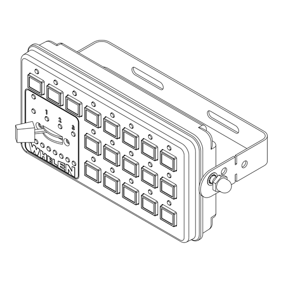
Installation/Operating Guide:
CanTrol™ Siren/Light Control System
ACTIVATION OF THIS
SIREN MAY DAMAGE
UNPROTECTED EARS!
AND
Wear
Protection!
(Basic)
CAUTION
Loud siren noise can cause
hearing damage and/or loss.
Refer to OSHA Section 1910.95 prior
to putting ANY siren into service!
Advertisement
Table of Contents

Subscribe to Our Youtube Channel
Related Manuals for Whelen Engineering Company CanTrol


Summary of Contents for Whelen Engineering Company CanTrol
- Page 1 ® ENGINEERING COMPANY INC. Installation/Operating Guide: 51 Winthrop Road Chester, Connecticut 06412-0684 CanTrol™ Siren/Light Control System Phone: (860) 526-9504 (Basic) Fax: (860) 526-4078 Internet: www.whelen.com Sales e-mail: autosale@whelen.com Canadian Sales e-mail: autocan@whelen.com Customer Service e-mail: custserv@whelen.com DANGER! Sirens produces extremely loud emergency warning tones! Exposure to these tones without proper and adequate hearing protection, could cause ear damage and/or hearing loss! The Occupational Safety &...
-
Page 2: Table Of Contents
Control Head with Priority Button ................... page 7 Hand-Held Control Head ....................page 7 Sample CanTrol System ......................page 12 CanTrol System Worksheet ....................page 13 CanTrol Installation Worksheet (J-4) ..................page 14 CanTrol Installation Worksheet (J-17) ................... page 15 Illustrations Bail Strap Mounting ....................... page 4 Hands-Free Transfer Relay .................... -
Page 3: Specifications
Specifications General Input Voltage 12.8 VDC ±20% Negative Ground Only Main Input Current 80 Amps Max. Main Input Fuse 2 Fuses @ 40 Amps ea. Standby Current (backlight off) Ign.On - 80mA (typ) / Ign.Off - 100 uA (typ) Operating Temperature -30°C to +60°C Storage Temperature -40°C to +70°C... -
Page 4: Amp/Relay Module
Check both A 1/4” port is provided on the CanTrol module for installation of the sides of the mounting surface before starting. If damage is microphone. -
Page 5: Wiring
Siren Speaker (Item 9) J17-6). Their input voltage may range from 0 to 12VDC. By default, these Route the ORG and BRN wires from the CanTrol module to the siren inputs are disabled and can be enabled as needed. speaker. -
Page 6: Public Address (Pa) Volume Adjustment
Locate the Radio Repeat adjustment potentiometer on the left #8 (Airhorn) - This button will broadcast the Airhorn tone as long as the side of the CanTrol module. Set the volume of the vehicle’s two-way radio button is pressed, over-riding other siren tones. -
Page 7: Control Head With Priority Button
Control Head with Priority Button This model operates the same as the standard control head except that Slide Switch 2 - Activates both front and rear warning lights. All vehicle the slide switch has been replaced with the Master Emergency Button. warning lights will flash in Synchronous Signal Alert 75 (Alternating). -
Page 8: Cantrol Module Identification
3 - LEDS2 This fuse (20 Amp) protects Outputs 9 thru 16. 11 - Diagnostic LEDs ERR (Error) LED 4 - Siren Speaker Steady CanTrol™ Controller Bus is set to Pos. Description OFF. Check Interface Box. Speaker (+) No Error. Not Used Single Flash Bad CanTrol™... -
Page 9: Wire Gage Calculation Chart
Wire Gauge Calculation Chart Maximum Current Draw Through The Wire 5 Amps 10 Amps 15 Amps 20 Amps 25 Amps 30 Amps 35 Amps 40 Amps 45 Amps 50 Amps 6 Feet 3 Feet Insufficient Insufficient Insufficient Insufficient Insufficient Insufficient Insufficient Insufficient 22 AWG... -
Page 10: System Wiring
CanTrol™ System Wiring Guide - 1 Horn Ring Transfer Relay TYCO-P&B P/N: VF4-45F11 (Not Included) From Vehicle Horn Relay ® LED OUTPUTS J4 (1-16) LC AUX 1,2,3 SIREN SPEAKERS To Vehicle LEDS LEDS SIREN FUSE J17-1 Car Horn J4-1 J - 1. -
Page 11: System Wiring
CanTrol™ System Wiring Guide - 2 Microphone Not For Use With The CanTrol™ Hand-Held Controller Justice WC Lightbar Shown For Reference ® Optional Microphone Extension PROGRAM ERR WC POW CTRL LOGIC INPUTS J17 HEAD LIGHTBAR PORT Cord Shown For Reference Only 1 2 3 Standard CanTrol™... -
Page 12: Sample Cantrol System
T he default wire assignments, as well as control head operations can easily be redefined using the CanTrol software . This flexibility makes it possible to design an almost limitless number of custom configurations based on your specific equipment. -
Page 13: Cantrol System Worksheet
CanTrol™ System Worksheet CanTrol Sys Wrksht J17-8 BLU - Radio Repeat J17-16 BLU - Radio Repeat This worksheet is provided to allow the installer to provide a visual record of what specific vehicle equipment is activated and/or controlled with specific inputs or outputs to the customer. -
Page 14: Cantrol Installation Worksheet (J-4)
CanTrol™Installation Worksheet (J-4) CanTrol Inst.Wrksht J- 10 1 1 12 13 14 15 16 6 7 8 HIGH CURRENT OUTPUTS J1 ® LED OUTPUTS J2 (17-32) TRAFFIC ADVISOR J10 LED OUTPUTS J4 (1-16) LC AUX 1,2,3 SIREN SPEAKERS LEDS LEDS... -
Page 15: Cantrol Installation Worksheet (J-17)
CanTrol™Installation Worksheet (J-17) CanTrol Wrksht J17 ® ERR WC POW CTRL PROGRAM LOGIC INPUTS J17 HEAD LIGHTBAR PORT 1 2 3 J-17 J17 - Logic Inputs Pos. Color Function J17-1 WHT/BRN _________________________________________________________________________________________________________________________________ J17-2 WHT/ _________________________________________________________________________________________________________________________________ J17-3 WHT/ _________________________________________________________________________________________________________________________________ J17-4 WHT/...
Need help?
Do you have a question about the CanTrol and is the answer not in the manual?
Questions and answers