Table of Contents
Advertisement
Quick Links
ENGINEERING COMPANY INC.
51 Winthrop Road
Chester, Connecticut 06412-0684
Phone: (860) 526-9504
Fax: (860) 526-4078
Internet: www.whelen.com
Sales e-mail: autosale@whelen.com
Canadian Sales e-mail: canadiansales@whelen.com
Customer Service e-mail: custserv@whelen.com
DANGER!
Sirens produce extremely loud emergency warning tones! Exposure to these tones without
proper and adequate hearing protection, could cause ear damage and/or hearing loss! The Occupational Safety &
Health Administration (www.osha.gov) provides information necessary to determine safe exposure times in
Occupational Noise Exposure Section 1910.95. Until you have determined the safe exposure times for your
specific application, operators and anyone else in the immediate vicinity should be required to wear an approved
hearing protection device. FAILURE TO FOLLOW THIS RECOMMENDATION COULD CAUSE HEARING LOSS!
Safety First
This document provides all the necessary information to allow your Whelen product to be properly and safely installed.
Before beginning the installation and/or operation of your new product, the installation technician and operator must
read this manual completely. Important information is contained herein that could prevent serious injury or damage.
•
Proper installation of this product requires the installer to have a good understanding of automotive electronics,
systems and procedures.
•
Whelen Engineering recommends the use of waterproof butt splices and/or connectors if that connector could be
exposed to moisture.
•
Failure to use specified installation parts and/or hardware will void the product warranty!
•
If mounting this product requires drilling holes, the installer MUST be sure that no vehicle components or other
vital parts could be damaged by the drilling process. Check both sides of the mounting surface before drilling
begins. Also de-burr any holes and remove any metal shards or remnants. Install grommets into all wire passage
holes.
•
If this manual states that this product may be mounted with suction cups, magnets, tape or Velcro®, clean the
mounting surface with a 50/50 mix of isopropyl alcohol and water and dry thoroughly.
•
Do not install this product or route any wires in the deployment area of your air bag. Equipment mounted or located
in the air bag deployment area will damage or reduce the effectiveness of the air bag, or become a projectile that
could cause serious personal injury or death. Refer to your vehicle owner's manual for the air bag deployment
area. The User/Installer assumes full responsibility to determine proper mounting location, based on providing
ultimate safety to all passengers inside the vehicle.
•
For this product to operate at optimum efficiency, a good electrical connection to chassis ground must be made.
The recommended procedure requires the product ground wire to be connected directly to the NEGATIVE (-)
battery post.
•
If this product uses a remote device to activate or control this product, make sure this control is located in an area
that allows both the vehicle and the control to be operated safely in any driving condition. DO NOT ATTEMPT TO
ACTIVATE OR CONTROL THIS DEVICE IN A HAZARDOUS DRIVING
SITUATION.
•
It is recommended that these instructions be stored in a safe place and
referred to when performing maintenance and/or reinstallation of this
product.
•
FAILURE TO FOLLOW THESE SAFETY PRECAUTIONS AND INSTRUCTIONS
COULD RESULT IN DAMAGE TO THE PRODUCT OR VEHICLE AND/OR
SERIOUS INJURY TO YOU AND YOUR PASSENGERS!
For warranty information regarding this product, visit www.whelen.com/warranty
©2013 Whelen Engineering Company Inc.
Form No.14624C (072413)
®
Page 1
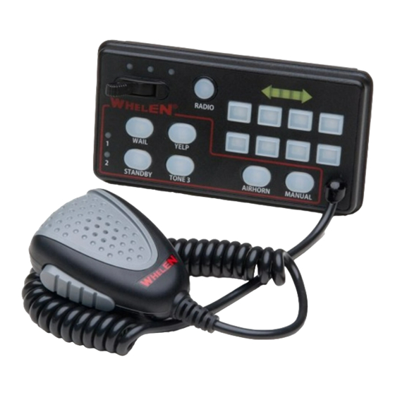
Installation Guide:
Dual Siren Control Center
Model 295SDA1
ACTIVATION OF THIS
SIREN MAY DAMAGE
UNPROTECTED EARS!
CAUTION
Loud siren noise can cause
hearing damage and/or loss.
Wear
Refer to OSHA Section 1910.95 prior
Protection!
to putting ANY siren into service!
Advertisement
Table of Contents

Subscribe to Our Youtube Channel
Related Manuals for Whelen Engineering Company 295SDA1


Summary of Contents for Whelen Engineering Company 295SDA1
- Page 1 Wear Refer to OSHA Section 1910.95 prior SERIOUS INJURY TO YOU AND YOUR PASSENGERS! Protection! to putting ANY siren into service! For warranty information regarding this product, visit www.whelen.com/warranty ©2013 Whelen Engineering Company Inc. Form No.14624C (072413) Page 1...
- Page 2 Route the control head cable (provided) from the amp/relay module to the designated There are two basic mounting brackets for the 295SDA1 control head. mounting location. Plug this cable securely One allows the control head to be mounted into your vehicle’s console (if into the rear of the control head.
- Page 3 To Horn BACKLIGHT (+) SPEAKER SPEAKER VEHICLE Button AUX INPUT (-) Wire Gage / AWG HORN SIREN DISABLE (+) SIREN DISABLE (-) 19.5 UNIT ENABLE (+) 15.5 24.5 10.5 16.5 41.5 RED/BLK WHT/VIO 12.5 19.5 15.5 WHT/GRN +12V 20.5 SPKR SPKR 17.5 CUT WIRE...
- Page 4 To change the settings, refer to When this button is pressed, the siren will produce a two out of sync. Programming the 295SDA1 for information on how to customize the combined Wail and yelp tones on both speakers. Pressing the TONE3 operation of the siren/lighting control center.
- Page 5 There are two programmable “Switch Types” associated with Traffic Advisor control, “Traffic Advisor Pattern Control” and “Traffic Advisor +VBAT FROM J4 Flash Control”. 295SDA1 AUX- A OUTPUT Normally Closed When a switch’s “Switch Type” has been programmed as “Traffic Advisor AUX-A OUTPUT Pattern Control”, this switch now takes control of designated Traffic...
- Page 6 J7, and pin 1 of J5 to (+) 12 volts only. 4. Store and activate the switch's “Switch Type”: The 295SDA1 has the ability to program both the siren switches and the • Press and release the RADIO switch.
- Page 7 To confirm that the factory defaults have To confirm entry into this configuration been restored, LED 3 on the Arrow indicator mode, LEDS 2 and 3 on the Arrow indicator will light up for two seconds. will light up. After the 2 seconds pass, all of the indicator lights will turn off and the AND…...
- Page 8 3. Add or delete momentary switches activated by the 5. Store and activate the configuration: selected switch: • Press and release the RADIO switch on both the “primary and secondary” units. • Press and release one of the 8 momentary switches to add or delete it from the selected switch’s configuration.
- Page 9 1. Put the unit into “indicator adjustment” Mode: 1. Put the unit into “Shutdown Delay adjustment” Mode: • Place the SLIDE SWITCH in the OFF position and turn all Momentary • Place the SLIDE SWITCH in the OFF position and turn all Momentary switches off.
- Page 10 • The other speaker will shut off for 2 seconds so that the new tone can Adjusting Radio Levels be clearly identified. • When the desired tone is generated, it is automatically saved as the To adjust RADIO or PA volume, override tone in that switch position for that speaker.
Need help?
Do you have a question about the 295SDA1 and is the answer not in the manual?
Questions and answers