Table of Contents
Advertisement
Quick Links
INSTRUCTION MANUAL
GENERATOR PROTECTIVE RELAY
1
2
3
4
6
7
8
Generator
Protective
Relay
SYNC-CHECK
U N D E R
O V E R
V O L T A G E
C U R R E N T
F R E Q U E N C Y
V O L T S
A M P S
36
37
38
39
40
41
42
43
FOR
BE3-GPR
9
10
11
12
13
16
18
PHASE
REACTIVE
GND-FAULT
DEAD-BUS
1 2
ANGLE
DELTA
TRIP
RESET
W A T T S
S E C O N D S
H E R T Z
D E G R E E S
44
45
46
47
48
49
50
51
52
53
20
22
24
26
R E V - P W R
Sync
TIME-DELAY
O N
O F F
54
55
56
57
58
59
60
61
62
63
Publication:
Revision:
31
32
33
34
35
BE3-GPR
Raise
Lower
Select
64
65
66
67
68
69
70
9 2782 00 990
F
01/2000
Advertisement
Table of Contents

Related Manuals for Basler BE3-GPR


Summary of Contents for Basler BE3-GPR
- Page 1 INSTRUCTION MANUAL GENERATOR PROTECTIVE RELAY BE3-GPR Generator Protective Relay BE3-GPR Raise SYNC-CHECK U N D E R O V E R PHASE REACTIVE GND-FAULT DEAD-BUS R E V - P W R Sync V O L T A G E...
- Page 2 INTRODUCTION This manual provides information concerning the operation and installation of BE3-GPR Generator Protective Relays. To accomplish this, the following is provided. • Specifications • Functional Description • Mounting Information • Communications • Testing Procedures WARNING TO AVOID PERSONAL INJURY OR EQUIPMENT DAMAGE, ONLY QUALIFIED PERSONNEL SHOULD PERFORM THE PROCEDURES PRESENTED IN THIS MANUAL.
- Page 3 First Printing: October 1996 Printed in USA © 1997, 1998, 2000 Basler Electric Co., Highland, IL 62249 January 2000 CONFIDENTIAL INFORMATION OF BASLER ELECTRIC COMPANY, HIGHLAND, IL. IT IS LOANED FOR CONFIDENTIAL USE, SUBJECT TO RETURN ON REQUEST, AND WITH THE MUTUAL UNDERSTANDING THAT IT WILL NOT BE USED IN ANY MANNER DETRIMENTAL TO THE INTEREST OF BASLER ELECTRIC COMPANY.
-
Page 4: Table Of Contents
CONTENTS SECTION 1 GENERAL INFORMATION ................1-1 Description....................1-1 Capabilities ....................1-1 Basic Stand-Alone Generator Version ........... 1-1 Basic Paralleled Generator Version............1-1 Optional Protective Functions ..............1-1 Control Enables..................1-1 Watchdog Timer..................1-1 Indicators ....................1-2 Communications ..................1-2 Outputs ...................... - Page 5 BE3-GPR Typical DC Control Circuit ..............4-6 BE3-GPR (NGF) S-2 With Single-Phase, Line-To-Line Sensing and Conditioning, and 5A CT .....................4-7 BE3-GPR (NGF) S-2 With Three-Phase, Line-To-Line Sensing and 1A CT..4-8 BE3-GPR (NGF) P-2 With Single-Phase, Line-To-Line Sensing and Conditioning, and 5A CTs ....................4-9 BE3-GPR (NGF) P-2 With Three-Phase, Three Wire, Line-To-Line Sensing and 5A CTs ......................4-10...
- Page 6 CONTENTS - Continued SECTION 5 NGF COMMUNICATIONS - Continued Metering.......................5-6 Enable Metering ....................5-6 Metering Screen....................5-7 Terminating Communications with the BE3-GPR..........5-8 SECTION 6 TOC COMMUNICATIONS ..................6-1 Introduction......................6-1 Installation ......................6-1 Operating Requirements ................6-1 Installing the Program on Your PC Using Windows 3.1 ......6-1 Installing the Program on Your PC Using Windows95.......6-1...
- Page 7 CONTENTS - Continued SECTION 7 TESTING - Continued Sync-Check....................7-4 Dead Bus ......................7-5 Contact Sensing ....................7-5 Trip Reset......................7-5 Failsafe Enable .....................7-6 Output Disable ....................7-6 Program Enable ....................7-6 SECTION 8 MAINTENANCE ....................8-1 General........................8-1 Troubleshooting....................8-1 SECTION 9 MANUAL CHANGE INFORMATION ..............9-1 Changes ......................9-1 Summary of Changes..................9-1 Introduction...
-
Page 8: Description
PTs and CTs are required. Optional protective features allow for customizing the BE3-GPRs to meet your system requirements. The BE3-GPR provides multiple functions in a single case -- a combination that yields significant savings in installation and setup. CAPABILITIES BE3-GPRs are packaged in metal cases for improved electromagnetic compatibility. -
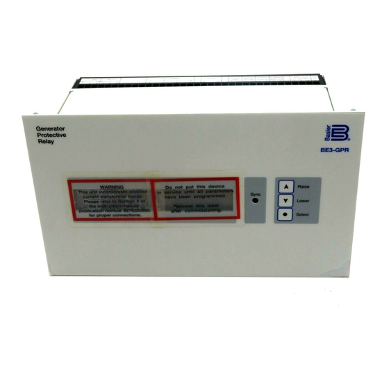
Page 9: Indicators
There are two indicators mounted on the front panel of the relay. The SYNC LED (present only in the BE3-GPR P units with the sync-check option) indicates that the generator and bus inputs are within the synchronization window set by the user. The liquid crystal display (LCD) is the main human-machine interface and has capabilities to show any and all information necessary for programming and interpreting relay actions. - Page 10 Phase angle is settable from 2 to 20 degrees in one degree steps, and Sync-Check With Dead Bus voltage difference is adjustable from 1 to 100 Vac in one volt steps. Both the time delay (which is variable from 0.2 to 2 seconds in 0.1 second steps), and the slip frequency (which is variable from 0.1 hertz to 1.0 hertz in 0.1 hertz steps) qualify the in-sync condition.
- Page 11 Timing Accuracy Within ±5% or 50 mSec, whichever is greater for time dial settings of D (51V Functions) greater than 0.1 and multiples of 2 to 40* times the pickup setting but not over 30 A for 5 A CT units or 6 A for 1 A CT units. * 3-40 times pickup for the A-curve.
-
Page 12: Contact Ratings
5 mAac or 1 mAdc RS-232 terminals 6 mAac or 1 mAdc Contact outputs 31 mAac or 1 mAdc Table 1-1. 51V Time Characteristic Curve Constants BE3-GPR Curve Curve BE Curve Name Trip Characteristic Constants Number Selection S1, Short Inverse 0.2663... -
Page 13: Style Chart
4 lb. STYLE CHART BE3-GPR relays are identified by a combination of letters and numbers that make up the style number and define the electrical characteristics and operational features. The model number, together with the style number, describe the options included in a specific device and appear on a relay side panel. - Page 14 BE3-GPR curves to existing electromechanical relay characteristics. Contact Customer Service Department of the Power Systems Group, Basler Electric, and request the drawing number to order a full-size (10 inch x 12 inch) Characteristic Curve graph on transparent paper (vellum).
- Page 15 General Information...
- Page 16 Figure 1-2. Time Characteristic Curve S1, Short Inverse, 99-1369, (Similar to ABB CO-2) General Information...
- Page 17 Figure 1-3. Time Characteristic Curve S2, Short Inverse, 99-1595 (Similar To GE IAC-55) 1-10 General Information...
- Page 18 Figure 1-4. Time Characteristic Curve L1, Long Inverse, 99-1369, (Similar to ABB CO-5) General Information 1-11...
- Page 19 1-12 General Information...
- Page 20 Figure 1-5. Time Characteristic Curve L2, Long Inverse, 99-1594, (Similar To GE IAC-66) General Information 1-13...
- Page 21 Figure 1-6. Time Characteristic Curve D, Definite Time, 99-1371, (Similar To ABB CO-6) 1-14 General Information...
- Page 22 Figure 1-7. Time Characteristic Curve M, Moderately Inverse, 99-1372, (Similar to ABB CO-7) General Information 1-15...
- Page 23 Figure 1-8. Time Characteristic Curve I1, Inverse Time, 99-1373 (Similar to ABB CO-8) 1-16 General Information...
- Page 24 Figure 1-9. Time Characteristic Curve I2, Inverse Time, 99-1597 (Similar to GE IAC-51) General Information 1-17...
- Page 25 Figure 1-10. Time Characteristic Curve V1, Very Inverse, 99-1374 (Similar to ABB CO-9) 1-18 General Information...
- Page 26 Figure 1-11. Time Characteristic Curve V2, Very Inverse, 99-1596 (Similar to GE IAC-53) General Information 1-19...
- Page 27 Figure 1-12. Time Characteristic Curve E1, Extremely Inverse, 99-1375 (Similar to GE IAC-11) 1-20 General Information...
- Page 28 Figure 1-13. Time Characteristic Curve E2, Extremely Inverse, 99-1598 (Similar to GE IAC-77) General Information 1-21...
- Page 29 Figure 1-14. Time Characteristic Curve A, Standard Inverse, 99-1621 1-22 General Information...
- Page 30 Figure 1-15. Time Characteristic Curve B, Very Inverse, 99-1376 General Information 1-23...
- Page 31 Figure 1-16. Time Characteristic Curve C, Extremely Inverse, 99-1377 1-24 General Information...
- Page 32 Figure 1-17. Time Characteristic Curve G, Long Time Inverse, 99-1622 General Information 1-25...
-
Page 33: Front Panel Display
Red LED illuminates for a sync or a deadbus condition and output contacts closed (Note: LED present only on the BE3-GPR P units with the sync-check feature). Pushbutton used to toggle the menu selections, scroll for setpoint adjustments, fast scroll by pressing for one second, and, when pressed after holding the SELECT pushbutton down, makes the menu selection sequence move in the forward direction. -
Page 34: Panel Connections
PANEL CONNECTIONS Figures 2-2 through 2-5 show the bottom and top panel connections for the BE3-GPR (NGF and TOC). Figure 2-2. BE3-GPR (NGF) Bottom Panel Figure 2-3. BE3-GPR (NGF) Top Panel Human-Machine Interface... - Page 35 Figure 2-4. BE3-GPR (TOC) Bottom Panel Figure 2-5. BE3-GPR (TOC) Top Panel Compression type terminal strips make wiring simple. These connections accept one #10 AWG wire or two #14 AWG wires. These operations are made even more simple by the user friendly labeling of the terminals.
-
Page 36: Functional Description
There are two basic BE3-GPR models: BE3-GPR S for standalone systems and BE3-GPR P for paralleled systems. Each model comprises a basic set of capabilities. This section describes the hardware and software functional descriptions for a BE3-GPR P with all available protective features. -
Page 37: Voltage Sensing And Conditioning
Voltage Sensing And Conditioning Monitored generator and bus voltages are sensed and scaled down to suitable internal circuit levels. Internal solid state analog switches select whether the generator voltage differential levels represent line- to-line or line-to-neutral values. The user determines these selections through menu options. The BE3- GPR requires a minimum sensing voltage of 10 volts to be applied for normal operation. - Page 38 For phase B and neutral ground fault current sensing: ∑ ∑ NGFn For phase A, B, and C current sensing: ∑ ∑ ∑ For single phase or 3 phase 3 wire sensing: ∑ ∑ ⋅ ⋅ For 3 phase 4 wire sensing: ∑...
-
Page 39: Output Relays
Timing Curves SOFTWARE Software embedded in the microprocessor controls all aspects of BE3-GPR functionality. This comprises power-up initialization, user front panel setup and configuration, hardware jumper input detection, protective function trip detection and annunciation, sync-check monitoring and annunciation, and remote RS-232 communications support. -
Page 40: Relay Setup And Configuration
Relay Setup And Configuration Function setup and system configuration is organized in a menu format on the front panel display. In order to scan through the current settings, the user must press the SELECT pushbutton. The user can only perform changes to these settings while the program enable hardware jumper is installed. (Note: The program enable hardware jumper is not required when using a personal computer to program relay settings.) Although the menu shown in Figures 3-3 through 3-8, shows only forward progression through the sequence, the user can adjust from this default at any of the function ON/OFF menus, by... - Page 41 If the function is enabled, the LCD displays the trip level for the function which the user can adjust through the use of the Raise and Lower keys. The incorporation of a fast scroll feature makes the adjustments less cumbersome; the user can access this feature by holding the Raise or Lower pushbutton for one second for each step of ten times the normal adjustment level.
- Page 42 Figure 3-3. Selection Menu ( Sheet 1 of 6) Functional Description...
- Page 43 Figure 3-4. Selection Menu (Sheet 2 of 6) Functional Description...
- Page 44 Figure 3-5. Selection Menu (Sheet 3 of 6) Functional Description...
- Page 45 Figure 3-6. Selection Menu (Sheet 4 of 6) 3-10 Functional Description...
- Page 46 Figure 3-7. Selection Menu (Sheet 5 of 6) 3-11 Functional Description...
- Page 47 Figure 3-8. Selection Menu (Sheet 6 of 6) 3-12 Functional Description...
-
Page 48: Remote Rs232 Communications And Support
REMOTE RS-232 COMMUNICATIONS AND SUPPORT Users can program the relay settings using a remote personal computer connected to the isolated terminal blocks. This allows the user to program the relay without directly accessing the buttons on the front panel. Remote programming does not interfere with normal operation. In order for remote pushbutton operations to begin, the personal computer must be running a terminal emulation program (e.g. - Page 49 Table 3-1. Available Commands Command Description V = d1 d1 = software version identification number (For Basler Electric Company use only) CFG = d1, d2, d3 (System d1 = auto reset: 0 (disabled) or 1(enabled) Configuration) d2 = CT Configuration: 1 (1A CT) or 5 (5A CT)
- Page 50 Table 3-1. Available Commands Command Description OC = d1, d2, d3, d4, d5, d6 (Overcurrent) d1 = overcurrent trip enable: 0 (disable) or 1 (enable) d2 = overcurrent trip level (Amps * 100) d3 = overcurrent reset level (Amps * 100) d4 = overcurrent time dial (seconds * 10) d5 = curve (Refer to Table 1-1) d6 =voltage restraint nominal: 0 (disable) or (volts)
-
Page 51: Default Settings
One, it provides a user friendly environment to change or make relay settings. Without the software, you must be familiar with the BE3-GPR terminal commands to program relay settings. With the software, on-screen displays guide you through the setting process. Two, the software provides a means to monitor the metering results through the communications interface. -
Page 52: Hardware Jumper Inputs
Hardware Jumper Inputs The software monitors the status of the hardware jumper terminal block inputs in order to determine what the required operations are for any given condition. Program Enable Software continuously reads this input to determine when the user may make changes to the settings. If installed, the relay settings may be altered as described in earlier in this section. -
Page 53: Section 4 Installation
Model and Style Number against the requisition and packaging list for agreement. Inspect for damage, and if there is evidence of such, immediately file a claim with the carrier and notify the Basler Electric Regional Sales Office, your Sales Representative or Sales Representative at Basler Electric, Highland, Illinois. -
Page 54: Installation
P R E S S E D - I N S T U D S ( 4 P L ) 9.450 (240.0) .250 8.950 (227.3) (6.35) 4.875 (123.9) 5.375 (136.5) .250 D2818-18 (6.35) 02-01-00 C U T O U T V I E W Figure 4-2. BE3-GPR Typical Overall Dimensions and Hole Locations (Semi-Flush Mounting) Installation... -
Page 55: General
MALE DB-9 R X D R X D D T R D T R SIG COMM SIG COMM BE3-GPR D S R D S R R Q S R Q S D2454-06 12-16-96 Figure 4-3. RS-232 Serial Communications Cable Connections... -
Page 56: System
System Figure 4-4 shows the connections for three-phase systems with either ABC rotation or ACB rotation. Unless otherwise noted, all connections shown in this manual assume ABC rotation. B U S G E N B U S B B U S A B E 3 - G P R C O N N E C T I O N S F O R T H R E E - P H A S E S Y S T E M S W I T H A B C R O T A T I O N . -
Page 57: Be3-Gpr, Ngf, Inputs And Outputs
The following figures show the BE3-GPR (NGF and TOC) relay unit connections. G E N SINGLE-PHASE L-L ONE PHASE L-L, THREE PHASE L-N, SINGLE-PHASE L-N OR THREE PHASE L-N GEN INPUT BUS INPUT G E N C B G R O U N D... -
Page 58: Be3-Gpr, Toc, Inputs And Outputs
81U#2 D.B. Figure 4-6. BE3-GPR, TOC, Inputs and Outputs T Y P I C A L B E 3 - G P R P R O T E C T I V E F U N C T I O N... -
Page 59: Be3-Gpr (Ngf) S-2 With Single-Phase, Line-To-Line Sensing And Conditioning, And 5A Ct
Figure 4-8. BE3-GPR (NGF) S-2 With Single-Phase, Line-To-Line Sensing and Conditioning, and 5A CT. Installation... -
Page 60: Be3-Gpr (Ngf) S-2 With Three-Phase, Line-To-Line Sensing And 1A Ct
Figure 4-9. BE3-GPR (NGF) S-2 With Three-Phase, Line-to-Line Sensing, and 1A CT Installation... -
Page 61: Be3-Gpr (Ngf) P-2 With Single-Phase, Line-To-Line Sensing And Conditioning, And 5A Cts
Figure 4-10. BE3-GPR (NGF) P-2 With Single-Phase, Line-to-Line Sensing and Conditioning, and 5A CTs. Installation... -
Page 62: Be3-Gpr (Ngf) P-2 With Three-Phase, Three Wire, Line-To-Line Sensing And 5A Cts
Figure 4-11. BE3-GPR (NGF) P-2 With Three-Phase, Three Wire, Line-to-Line Sensing, and 5A CTs 4-10 Installation... -
Page 63: Be3-Gpr (Ngf) P-2 With Three-Phase, Four Wire, Line-To-Neutral Sensing And Conditioning, And 5A Cts
Figure 4-12. BE3-GPR (NGF) P-2 With Three-Phase, Four Wire, Line-to-Neutral Sensing and Conditioning, and 5A CTs Installation 4-11... -
Page 64: Be3-Gpr (Toc) S-1 With Single-Phase, Line-To-Line Sensing And Conditioning, And 5A Ct
Figure 4-13. BE3-GPR (TOC) S-1 With Single-Phase, Line-To-Line Sensing and Conditioning, and 5A CT. 4-12 Installation... -
Page 65: Be3-Gpr (Toc) S-1 With Three-Phase, Line-To-Line Sensing And 1A Ct
Figure 4-14. BE3-GPR (TOC) S-1 With Three-Phase, Line-to-Line Sensing, and 1A CT Installation 4-13... -
Page 66: Be3-Gpr (Toc) P-1 With Single-Phase, Line-To-Line Sensing And Conditioning, And 5A Cts
Figure 4-15. BE3-GPR (TOC) P-1 With Single-Phase, Line-to-Line Sensing and Conditioning, and 5A CTs. 4-14 Installation... -
Page 67: Be3-Gpr (Toc) P-1 With Three-Phase, Three Wire, Line-To-Line Sensing And 5A Cts
Figure 4-16. BE3-GPR (TOC) P-1 With Three-Phase, Three Wire, Line-to-Line Sensing, and 5A CTs Installation 4-15... -
Page 68: Be3-Gpr (Toc) P-1 With Three-Phase, Four Wire, Line-To-Neutral Sensing And Conditioning, And 5A Cts
Figure 4-17. BE3-GPR (TOC) P-1 With Three-Phase, Four Wire, Line-to-Neutral Sensing and Conditioning, and 5A CTs 4-16 Installation... -
Page 69: Ngf Communications
INSTALLATION BE3-GPR Windows Software contains a setup utility that installs the program on your personal computer (PC). When it installs the program, an uninstall icon is created that you may use to uninstall (remove) the program from your PC. If your PC has the minimum operating requirements listed in the following paragraph, then choose either Installing The Program On Your PC Using Windows ... -
Page 70: Initializing Communications With The Be3-Gpr
Review what we have done up to this point. You have loaded the software on your computer and you have the Basler Electric directory with the BE3-GPR icon. You have also connected the BE3-GPR unit to the computer, the system, and supplied operating power. Now you are ready to initialize communications. - Page 71 Select a comm port (like Comm 1 in Figure 5-3) and Initialize it. This opens the communication port and returns the current settings from the BE3-GPR unit. You do not have to select the communication protocol parameters because the software application program does that for you. Figure 5-4 is a sample of the screen showing the settings returned from the BE3-GPR unit.
-
Page 72: Sending, Getting, And Displaying Data
Executing this communications command updates the BE3-GPR unit with the settings currently displayed on the settings screens. Get From Relay Executing this communications command retrieves the settings from the BE3-GPR unit and displays those settings on the settings screens. Display Data... -
Page 73: Saving, Printing, And Opening Files
File Save If you have changed the settings on a specific BE3-GPR unit, you may want to save those settings for reference or future use. For example, you make the changes to a unit that is in your test system and you want to save the file as Test1. -
Page 74: File Open
Suppose that after you reviewed either the BE3-GPR unit performance or the actual settings, you wanted to make a change in those settings but did not have the BE3-GPR unit available. Open the Test1 file using a word processor such as Windows NoteBook, WordPerfect, or Microsoft Word. -
Page 75: Metering Screen
10 volts. Metering screen status indicators are displayed only for neutral ground fault sensing BE3-GPR relays with Version 1.01 or later software. PT and CT ratios can be entered to correct for external Pts and Cts used on the system. PT ratios up to 100:1 and CT ratios up to 2000:1 are allowed. -
Page 76: Terminating Communications With The Be3-Gpr
TERMINATING COMMUNICATIONS WITH THE BE3-GPR Pull down the Communications menu and select Close (Figure 5-10). When you execute the Close command, the communications and the BE3-GPR Windows software are terminated. Figure 5-10. Terminating Communications NGF Communications... -
Page 77: Toc Communications
INSTALLATION BE3-GPR Windows Software contains a setup utility that installs the program on your personal computer (PC). When it installs the program, an uninstall icon is created that you may use to uninstall (remove) the program from your PC. If your PC has the minimum operating requirements listed in the following paragraph, then choose either Installing The Program On Your PC Using Windows ... -
Page 78: Initializing Communications With The Be3-Gpr
Review what we have done up to this point. You have loaded the software on your computer and you have the Basler Electric directory with the BE3-GPR icon. You have also connected the BE3-GPR unit to the computer, the system, and supplied operating power. Now you are ready to initialize communications. - Page 79 Select a comm port (like Comm 1 in Figure 6-3) and Initialize it. This opens the communication port and returns the current settings from the BE3-GPR unit. You do not have to select the communication protocol parameters because the software application program does that for you. Figure 6-4 is a sample of the screen showing the settings returned from the BE3-GPR unit.
-
Page 80: Sending, Getting, And Displaying Data
Executing this communications command updates the BE3-GPR unit with the settings currently displayed on the settings screens. Get From Relay Executing this communications command retrieves the settings from the BE3-GPR unit and displays those settings on the settings screens. Display Data... -
Page 81: Saving, Printing, And Opening Files
SAVING, PRINTING, AND OPENING FILES BE3-GPR software also allows the user to save setup configurations to a disk. This allows a user to save multiple setups for later use and saves setup time when configuring multiple units. These files may also be printed for a hard copy reference and opened in several different ways. -
Page 82: File Open
Suppose that after you reviewed either the BE3-GPR unit performance or the actual settings, you wanted to make a change in those settings but did not have the BE3-GPR unit available. Open the Test1 file using a word processor such as Windows NoteBook, WordPerfect, or Microsoft Word. Use normal editing techniques to change the settings values and then save the file with either the same name or a new name. -
Page 83: Metering Screen
Figure 6-9. Metering Screen TERMINATING COMMUNICATIONS WITH THE BE3-GPR Pull down the Communications menu and select Close (Figure 6-10). When you execute the Close command, the communications and the BE3-GPR Windows software are terminated. Figure 6-10. Terminating Communications TOC Communications... -
Page 84: Testing
SECTION 7 • • • • TESTING GENERAL This Section provides a simple test procedure for testing BE3-GPR relays. EQUIPMENT REQUIRED • Personal computer with RS-232-C serial link and running a terminal emulator program. • DC Power Supply: 12-24 VDC adjustable, 0.5A. -
Page 85: Undervoltage Trip
Undervoltage Trip Step 1. Monitor the UND VOLT output contacts, terminals 40 and 41, for the trip condition. Step 2. Reduce phase A, line-to-neutral voltage from 69.3 V to 50 V . The relay should be flashing the undervoltage tripped condition on the front panel LCD. Return the voltage to 69.3 V the LCD should return to the un-tripped ON display. -
Page 86: Overfrequency Trip (Line-To-Line Frequency Sensing)
Step 4. Increase phase B, line-to-neutral voltage from 69.3 V to 100 V . The relay should be flashing the overvoltage tripped condition on the front panel LCD. Return the voltage to 69.3 and the LCD should return to the un-tripped ON display. Step 5. -
Page 87: Reverse Power Trip (1A Ct B Current Sensing)
Step 3. Set AC current phase angle to 180° relative to phase B-to-Neutral voltage. Increase AC current from 0 to 0.5 Amps. The relay should be flashing the reverse power tripped condition on the front panel LCD. Return the current level to 0 Amps and the LCD should return to the un-tripped ON display. -
Page 88: Dead Bus
Step 5. Monitor the SYNC CHK output contacts, terminals 67 and 68, for the in-sync condition. Step 6. Use the front panel keypad to scroll though the LCD based setup menu and enable the Sync-Check function, but leave all sync related settings, including dead bus disabled, at their default levels. -
Page 89: Failsafe Enable
Failsafe Enable Step 1. Remove the toggle switch and connect it to the FAIL SF ENABLE input (terminals 10 and 11). With the toggle switch in the open position the monitored overvoltage trip contacts should also be open. Step 2. Close the toggle switch to enable the failsafe mode. -
Page 90: Maintenance
If the relay fails to function properly, follow the procedures in Table 8-1, Troubleshooting. If addition maintenance is required, consult the Customer Service Department of the Power Systems Group, Basler Electric, for a return authorization number prior to shipping. -
Page 91: Manual Change Information
SECTION 9 • • • • MANUAL CHANGE INFORMATION CHANGES Substantive changes in this manual to date are summarized in Table 9-1. Table 9-1. Summary of Changes Revision Summary of Changes ECA/ECO Date Minor clarifications and error corrections were made. 15953 02/97 Manual was revised to include patent information.
Need help?
Do you have a question about the BE3-GPR and is the answer not in the manual?
Questions and answers