Sign In
Upload
Manuals
Brands
YOKOGAWA Manuals
Test Equipment
DL9140 Series
YOKOGAWA DL9140 Series Oscilloscope Manuals
Manuals and User Guides for YOKOGAWA DL9140 Series Oscilloscope. We have
3
YOKOGAWA DL9140 Series Oscilloscope manuals available for free PDF download: User Manual, Operation Manual
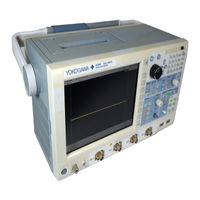
YOKOGAWA DL9140 Series User Manual (539 pages)
Digital Oscilloscope
Brand:
YOKOGAWA
| Category:
Test Equipment
| Size: 14 MB
Table of Contents
Checking the Contents of the Package
5
Safety Precautions
8
Waste Electrical and Electronic Equipment
10
Symbols and Notation Used in this Manual
11
Workflow
12
Table of Contents
13
Chapter 1 Names and Functions of Parts
18
Top Panel, Front Panel, and Rear Panel
18
Screen Display
23
Chapter 2 Explanation of Functions
25
Block Diagram
25
Channels and Displayed Waveforms
26
Vertical and Horizontal Axes
27
Triggers
32
Acquisition Conditions
40
Computation
48
Analyzing and Searching
50
Communications
56
Other Useful Functions
57
Chapter 3 Making Preparations for Measurements
61
Installing the Instrument
61
Connecting the Power
63
Connecting the Probe
66
Compensating the Probe (Phase Correction)
69
Setting the Date and Time
71
Chapter 4 Basic Operations
83
Performing Auto Setup
83
Storing and Recalling Setup Data
86
Performing Calibration
89
Chapter 5 Vertical and Horizontal Axes
91
Setting the Offset Voltage
91
Setting the Vertical Position of the Waveform
93
App
94
Setting the Input Coupling
94
Setting Bandwidth Limits
96
Setting the Probe Attenuation
97
Index
98
Setting Time Axis (T/DIV)
99
Using the Auto Scale Function
100
Canceling the Offset Value
101
Turning the Display of the Scale Value ON/OFF
103
Automatic Zero Adjustment of the Current Probe
105
Chapter 6 Triggering
107
Setting the Trigger Position
107
Setting the Trigger Delay
108
Setting the Hold-Off Time
111
Setting the Trigger Coupling, HF Rejection, Trigger Hysteresis, and Window Comparator
116
Activating an Edge Trigger
118
Activating a Conditional Edge Trigger
118
Activating a Trigger on a State Condition
122
Activating a Trigger on the or Logic of Multiple Edge Triggers
126
Activating a Trigger on a Pulse Width
128
Activating a Trigger on a Conditional Pulse Width
132
Activating a Trigger on a State Condition True Period
136
Setting the TV Trigger
140
Triggering on a Serial Pattern Signal
146
Triggering on an I C Bus Signal
153
Triggering on a CAN Bus Signal
161
Triggering on a LIN Bus Signal
163
Triggering on a SPI Bus Signal
174
Triggering on a UART Signal
178
Activating a Trigger on an Event Cycle, Delay, or Sequence
180
Chapter 7 Acquisition and Display
186
Setting the Acquisition Mode
186
Turning High Resolution Mode ON/OFF
188
Setting the Record Length
189
Turning Repetitive Sampling Mode ON/OFF
190
Turning Interleave Mode ON/OFF
191
Displaying Accumulated Waveforms
193
Setting the Action-On-Trigger Function
197
Activating the Action-On-Trigger Function Using GO/NO-GO Results
201
Setting Waveform Zone GO/NO-GO Determination Conditions
207
Setting Rectangular Zone GO/NO-GO Determination Conditions
213
Setting Polygonal Zone Go/No-Go Determination Conditions
217
Setting Waveform Parameter GO/NO-GO Determination Conditions
221
Setting FFT Parameter GO/NO-GO Determination Conditions
225
Setting X-Y Waveform Parameter GO/NO-GO Determination Conditions
229
Setting Telecom Test GO/NO-GO Determination Conditions
232
Chapter 8 Display
236
Zooming the Waveform
236
Changing the Display Format
241
Setting the Interpolation Method
243
Changing the Graticule
244
Adjusting the Backlight
245
Taking and Clearing Snapshots
247
Setting the Translucent Display, Waveform Display Colors, and Brightness
248
Chapter 9 Computation
254
Performing Linear Scaling
254
Performing Arithmetic Functions
256
Performing Integration
258
Shifting the Phase
260
Setting a Filter (IIR Filter)
262
Smoothing Waveforms (Using a Moving Average)
265
User-Defined Computation (Optional)
271
Chapter 10 Analysis and Search
291
Performing Automated Measurement of Waveform Parameters
291
Calculating Statistics on the Measured Waveform Parameter Values
300
Performing a Telecom Test (Mask Test and Eye Pattern Measurement)
304
Viewing the Phase between Measured Waveforms on the XY Display
311
Displaying a Histogram, Trend, or List of the Automatically Measured Waveform Parameters
320
Selecting the Search Type and Skip Mode, Executing the Search, and Displaying the Results
333
Searching Waveform Signals
338
Searching Serial Pattern Signals
343
Chapter 11 Displaying and Searching History Waveforms
361
Searching History Waveforms Using a Rectangular Zone (RECT History Search)
361
Searching History Waveforms Using a Polygonal Zone (POLYGON History Search)
364
Searching History Waveforms Using FFT Parameters (FFT History Search)
374
Chapter 12 Printing Screen Images
386
Printing Using the Built-In Printer (Optional)
386
Printing Using a USB Printer
387
Printing Using a Network Printer(Optional)
390
Chapter 13 Saving and Loading Measurement Data
391
Flash ATA Memory Card
391
Connecting a USB Storage Medium to the USB Port
392
Connecting to a Network Drive
393
Saving/Loading the Setup Data
394
Saving/Loading the Measurement Data
400
Saving and Loading Accumulated and Snapshot Waveforms
407
Saving/Loading Waveform Zones, Polygonal Zones, and Mask Patterns
411
Saving Screen Image Data
415
Saving Analysis Results
418
Changing the File Attributes and Deleting Files
422
Copying/Moving Files
425
Changing the Directory Name or File Name of the Storage Medium/Creating Directories
428
Connecting to a PC Using the USB Port
431
Chapter 14 Displaying Reference Waveforms
434
Displaying Stored Data as Reference Waveform
434
Displaying Waveforms Inverted
436
Saving Data
437
Displaying Scale Values and Labels
438
Displaying History Waveforms Automatically
439
Displaying the Acquisition Time of a Loaded Waveform
440
Chapter 15 Ethernet Communications (Optional)
441
Connecting the DL9000 to the Network
441
Setting the TCP/IP
443
Saving and Loading Measurement/Setup/Image Data on a Network Drive
453
Setting the Mail Transmission (SMTP Client Function)
456
Using SNTP to Set the Date and Time
460
Using a PC to Monitor the DL9000 and Change Its Settings (Web Server)
464
Setting the the Network Printer
470
Checking the Availability of the Ethernet Interface
472
Configuring A Firewall
473
Initializing All Ethernet Interface Settings (Only on Models with the LXI Option, /C9 and /C12)
475
Chapter 16 Rear Panel Input and Output
477
External Trigger Input (TRIG IN)
477
Trigger Output (TRIG OUT)
478
RGB Video Signal Output (RGB VIDEO OUT)
479
GO/NO-GO Signal Output
480
Trigger Comparator Signal Output
482
Chapter 17 Other Operations
483
Changing the Message Language, Menu Language, and Font Size, and Turning ON/OFF the Click Sound
483
Listing the Setup Data
485
Changing the USB Keyboard Language
486
Chapter 18 Troubleshooting, Maintenance, and Inspection
487
If a Problem Occurs
487
Messages and Corrective Actions
489
Carrying out a Self-Test
493
System Overview
496
Collectively Deleting the Data in the Internal Memory and Built-In Hard Disk
497
Formatting Internal Memory and Built-In Hard Disk
498
Recommended Replacement Parts
499
Chapter 19 Specifications
500
Models
500
Input Section
500
Trigger Section
501
Time Axis
503
Display Section
503
Functions
503
Built-In Printer (/B5 Option)
506
Auxiliary Inputs and Outputs
507
Storage
508
Computer Interfaces
509
General Specifications
510
External Dimensions
513
Appendix 1 Relationship between the Time Axis Setting, Sample Rate and Record Length
515
Appendix 2 How to Calculate the Area of a Waveform
527
Appendix 3 Key Assignments for the USB104 Keyboard
531
Appendix 4 Waveform Parameter Integrals and Derivatives
531
Appendix 5 ASCII Data File Format
531
Index
532
Advertisement
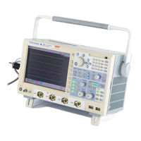
YOKOGAWA DL9140 Series User Manual (256 pages)
DL9040/DL9140/DL9240 Series Digital Oscilloscope Communication Interface
Brand:
YOKOGAWA
| Category:
Test Equipment
| Size: 4 MB
Table of Contents
How to Use this Manual
4
Table of Contents
7
Chapter 1 Overview of the USB Interface
9
Part Names and Functions
9
USB Interface Functions and Specifications
10
Connection Via the USB Interface
11
Setting the DL9000 (USB)
12
Chapter 2 Ethernet Interface
13
Part Names and Functions
13
Ethernet/VXI-11 Interface Features and Specifications
14
Connecting the Ethernet/VXI-11 Interface
16
Setting the DL9000 (Network)
17
Chapter 3 Overview of the GP-IB Interface
19
Part Names and Functions
19
Connecting the GP-IB Card
20
GP-IB Interface Functions
21
GP-IB Interface Specifications
22
Setting the DL9000 (GP-IB)
23
Responses to Interface Messages
24
Chapter 4 Before Programming
26
Messages
26
Commands
28
Response
30
Data
31
Synchronization with the Controller
33
Chapter 5 Commands
35
List of Commands
35
Acquire Group
68
Analysis Group
69
Asetup Group
99
Calibrate Group
100
Channel Group
101
Clear Group
103
Communicate Group
104
Cursor Group
106
Display Group
116
FILE Group
119
Gonogo Group
125
Hcopy Group
134
History Group
136
Image Group
146
Initialize Group
147
MATH Group
148
Measure Group
156
Reference Group
165
SNAP Group
171
Sstart Group
172
Start Group
173
Status Group
174
STOP Group
175
System Group
176
Telecomtest Group
177
Timebase Group
182
Trigger Group
183
Waveform Group
234
Common Command Group
238
Chapter 6 Status Reports
242
Overview of the Status Report
242
Status Byte
244
Standard Event Register
245
Extended Event Register
246
Output Queue and Error Queue
247
Appendix
248
Appendix 1 ASCII Character Codes
248
Error Messages
249
App
250
Appendix 3 Waveform Parameter Name Table
251
Appendix 4 Eye Pattern Parameter Name Table
252
YOKOGAWA DL9140 Series Operation Manual (29 pages)
Digital Oscilloscope
Brand:
YOKOGAWA
| Category:
Test Equipment
| Size: 2 MB
Table of Contents
Table of Contents
3
Flow of Operation
4
Names and Functions of Front Panel Controls
5
Parts of the Screen
8
Basic Key and Rotary Knob Operation
11
Introduction to Main Functions
13
Working with the DL9000
18
Preparing for an Observation
18
Displaying a Waveform on the Screen
20
Changing Waveform Display Conditions
21
Changing Trigger Settings
23
Measuring a Waveform
25
Zooming a Waveform
26
Printing and Saving a Waveform
27
Advertisement
Advertisement
Related Products
YOKOGAWA DL9040 Series
YOKOGAWA DL9040L
YOKOGAWA DL9140L
YOKOGAWA DL9240L
YOKOGAWA DL9000 Series
YOKOGAWA DL9240 Series
YOKOGAWA ScopeCorder DL950
YOKOGAWA DL 1520L
YOKOGAWA DLM3000
YOKOGAWA DL1720
YOKOGAWA Categories
Measuring Instruments
Test Equipment
Transmitter
Controller
Media Converter
More YOKOGAWA Manuals
Login
Sign In
OR
Sign in with Facebook
Sign in with Google
Upload manual
Upload from disk
Upload from URL