Table of Contents
Advertisement
Quick Links
Table of Contents
Pre-Delivery Manual
Read the operator's manual entirely. When you see this symbol, the subsequent
!
instructions and warnings are serious - follow without exception. Your life and
the lives of others depend on it!
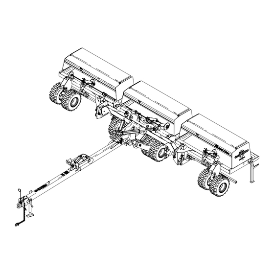
Cover illustration may show optional equipment not supplied with standard unit.
ORIGINAL INSTRUCTIONS
© Copyright 2019
Table of Contents
Three-Section Folding Drill
Manufacturing, Inc.
www.greatplainsmfg.com
Printed 4/25/19
3S-3000
15485
EN
195-144M
Advertisement
Table of Contents

Subscribe to Our Youtube Channel
Related Manuals for GREAT PLAINS 3S-3000 Series


Summary of Contents for GREAT PLAINS 3S-3000 Series
- Page 1 Table of Contents Pre-Delivery Manual 3S-3000 Three-Section Folding Drill Manufacturing, Inc. www.greatplainsmfg.com Read the operator’s manual entirely. When you see this symbol, the subsequent instructions and warnings are serious - follow without exception. Your life and the lives of others depend on it! 15485 Cover illustration may show optional equipment not supplied with standard unit.
- Page 2 Table of Contents Table of Contents...
-
Page 3: Table Of Contents
Great Plains Manufacturing, Inc. provides this publication “as is” without warranty of any kind, either expressed or implied. While every precaution has been taken in the preparation of this manual, Great Plains Manufacturing, Inc. assumes no responsibility for errors or omissions. Neither is any liability assumed for damages resulting from the use of the information contained herein. - Page 4 3S-3000 Table of Contents 4/25/19 Table of Contents 195-144M...
-
Page 5: Important Safety Information
3S-3000 Table of Contents Important Safety Information For your safety, thoroughly read Important Safety Information in the operator’s manuals before proceeding. Look for Safety Symbol The SAFETY ALERT SYMBOL indicates there is a potential hazard to personal safety involved and extra safety precaution must be taken. - Page 6 3S-3000 Table of Contents Important Safety Information Check for Overhead Lines Drill markers contacting overhead electrical lines can introduce lethal voltage levels on drill and tractor frames. A person touching almost any metal part can complete the circuit to ground, resulting in serious injury or death. ...
- Page 7 Keep all safety decals clean and legible. Replace all damaged or missing decals. Order new decals from your Great Plains dealer. Refer to this section for proper decal placement. When ordering new parts or components, also request corresponding safety decals.
-
Page 8: Introduction
Table of Contents Introduction Great Plains Manufacturing wants you to be satisfied with any new machine delivered by the Great Plains Trucking network. To ease the assembly task and produce a properly working machine, read this entire manual before assembling or setting up new equipment. -
Page 9: Using This Manual
For additional help with understanding these assembly instructions or for any other assembly or setup related questions, please contact our service department at the following address: Great Plains Service Department 1525 E. North St. P.O. Box 5060 Salina, KS 67402-5060 Or call us at (800) 270-9302 to speak over the phone with a service representative. -
Page 10: Preparation
3S-3000 Table of Contents Preparation Step-by-step instructions for assembling the implement begin in the next section of the manual. Before commencing work, review the Tools Required and Pre-Assembly Checklist to make sure you have all necessary parts and equipment. The implement is shipped via flat bed truck. It is the dealer’s responsibility to unload the new machine. -
Page 11: Before Unloading Truck
3S-3000 Table of Contents Preparation Before Unloading Truck Before unloading the drill from the truck, connect all opener springs (1) to the opener frames (2). Opener Damage Risk: To prevent damage to openers, make sure all openers are connected before unloading the drill. Overview of Work All fasteners and miscellaneous components are located in their assembly location, or in bags/cartons... -
Page 12: Assembly
3S-3000 Table of Contents Assembly Position for Assembly 1. Unload mainframe (standard load) or drill (wide load) from truck and place it in a location that allows for: • tow away depth: 28 feet (8.5m) plus length of tractor plus turning room •... - Page 13 3S-3000 Table of Contents Assembly Figure 4 15608 Tongue Installation and Hose Routing 4/25/19 Table of Contents 195-144M...
-
Page 14: Install Center Box On Frame
3S-3000 Table of Contents Assembly Install Center Box on Frame Refer to Figure 5 10. Pin the drill hitch to a tractor with a minimum of 100 horsepower to secure the drill frame for further assembly. 11. Center the center box frame assembly (1) behind the mainframe and bolt it in place with the eight ... -
Page 15: Install Wing Box Frames
3S-3000 Table of Contents Assembly Install Wing Box Frames Refer to Figure 6 12. Unfold the wing toolbars (1) until they contact the There are two cross holes so the slot in the nut center box frame. should align with a hole with less than additional rotation of the nut. -
Page 16: Installing Transfer Driveshaft
3S-3000 Table of Contents Assembly Installing Transfer Driveshaft Refer to Figure 7 19. Remove the transfer drive subassembly (1) from the drill seed box. The transfer drive assembles to the right side of the drill, and transfers the drive power to the center box assembly. -
Page 17: Connecting Opener Lift Hoses
3S-3000 Table of Contents Assembly Connecting Opener Lift Hoses Refer to Figure 8 end of the inner opener lift cylinder (3) of each wing 23. Connect the -inch hydraulic hoses (1) coming from frame. the back side of the wing pressure control valve to the base end tees (2) on the inner opener lift cylinder This is the hose which should extend beyond the (3) of each wing frame. -
Page 18: Install Press Wheels
3S-3000 Table of Contents Assembly Refer to Figure 9 26. Place all tees (8) which rest on the center box frame on the right side of the formed bracket (10) welded 8 14 to the center of the frame. This keeps them out of the clutch linkage which is left of center. -
Page 19: Install Ladder Mounts
3S-3000 Table of Contents Assembly Install Ladder Mounts Refer to Figure 12 or Figure 13 Location of the ladder mounts depends on whether the drill has the small seeds option. • For drills without the small seeds option, refer to Figure 12 as a reference. -
Page 20: Install Ladders
3S-3000 Table of Contents Assembly Install Ladders The ladders mount between the lugs (1) of the upper mounts. Flat washers are placed between ladder side frame and the lugs. Hex head bolts install from the inside, to minimize obstructions to foot movement during climbing. -
Page 21: Install Handles And Amber Lights
3S-3000 Table of Contents Assembly Install Handles and Amber Lights A handle and an amber light will need to be installed at the rear of each wing. Start with the right wing: Refer to Figure 16 1. At the ladder end of the right wing, install a handle (1) ... -
Page 22: Other Assembly Items
3S-3000 Table of Contents Assembly Other Assembly Items There are a few additional standard components, and several possible optional items, that are not factory installed. Some of these, which follow in this chapter, need to be installed prior to first hydraulic hookup. Others are installed after hookup, bleeding and leveling. -
Page 23: Open Center Conversion
3S-3000 Table of Contents Assembly Open Center Conversion If the drill was shipped with an Open Center kit, it is not factory-installed. Install it now. An installation manual is provided. Figure 20 18750 Open Center Conversion Point Row Option If the Point Row Option was ordered with the drill, the hydraulics and drill electrical lead are factory-installed. -
Page 24: Setup
3S-3000 Table of Contents Setup The assembly steps of the preceding chapter must be completed prior to setup. Setup steps consist of: 1. Hitch to suitable tractor. 2. Connect hydraulics. 3. Bleed hydraulics. 4. Level drill. 5. Install any options not factory-installed. Hitching You may be severely injured or killed by being crushed between the tractor and drill. - Page 25 3S-3000 Table of Contents Setup Refer to Figure 23 and Figure 24 To adjust the drill hitch to match your tractor-drawbar height, mount tongue jack on side of tongue. Use jack to raise drill tongue so lowest hitch hole is 18 inches (45.7cm) above ground level with drill lowered to FIELD position.
-
Page 26: Electrical Connections
3S-3000 Table of Contents Setup Electrical Connections Refer to Figure 26 Plug drill electrical lead into tractor seven-pin connector. Figure 26 26467 Lighting Connector Refer to Figure 27 If the drill is equipped with the optional shaft monitor, mate the connector for the cab display. Figure 27 34222 Shaft Monitor Connector... -
Page 27: Hydraulic Hose Hookup
Refer to Figure 29 Great Plains hydraulic hoses have color coded handle grips to help you hookup hoses to your tractor outlets. Hoses that go to the same remote valve are marked with the same color. -
Page 28: Bleeding Hydraulics
3S-3000 Table of Contents Setup Bleeding Hydraulics To function properly, the hydraulics must be free of air. If hydraulics have not been bled, they will operate with jerky, uneven motions and could cause wings to drop rapidly during folding or unfolding. If hydraulics were not bled during initial implement setup or if you replace a part in hydraulic system during the life of the drill, complete the following procedures. -
Page 29: Bleeding Fold Hydraulics
3S-3000 Table of Contents Setup Bleeding Fold Hydraulics Refer to Figure 30 1. Review warnings, bleeding notes and system 6. Slowly supply oil to base end of fold cylinders (4) information on page 24. until oil appears at loosened hose fitting. Tighten base end hose fitting and cycle fold cylinders in and 2. -
Page 30: Bleeding Opener Lift Hydraulics
3S-3000 Table of Contents Setup Bleeding Opener Lift Hydraulics Refer to Figure 31 1. Review warnings, bleeding notes and system 6. Slowly supply oil to top side of pressure-control information on page 24. valves until oil begins to appear at a loosened hose fitting. -
Page 31: Bleeding Transport Lift Hydraulics
3S-3000 Table of Contents Setup Bleeding Transport Lift Hydraulics Refer to Figure 32 1. Start with the transport axle in the lowered (field) position, and the box lift cylinder (at the middle of the tongue) completely retracted. Loosen the base end NEVER CRAWL UNDER THE DRILL IN THE RAISED hose fitting at the elbow on the left transport lift POSITON WITHOUT THE CYLINDER LOCK CHANNELS... -
Page 32: Bleeding Marker Hydraulics
3S-3000 Table of Contents Setup Bleeding Marker Hydraulics You may be injured if hit by a folding or unfolding marker. Markers may fall quickly and unexpectedly if the hydraulics fail. Never allow anyone near the drill when folding or unfolding markers. 1. -
Page 33: Leveling The Drill
3S-3000 Table of Contents Setup Leveling the Drill To perform leveling, the drill must be hitched to a tractor, with at least the hydraulics connected. Raising openers on unfolded, unhitched drill will cause drill tongue to rise suddenly, which could cause serious injury or death. -
Page 34: Wing Box Alignment
3S-3000 Table of Contents Setup Wing Box Alignment 1. Place a block ahead of the wing gauge wheels. Refer to Figure 36 2. Pull forward against blocks to rock wing frames back. Pull forward until stop bolts (3) are firmly against toolbars. -
Page 35: Align Transfer Drive Shaft
3S-3000 Table of Contents Setup Align Transfer Drive Shaft Refer to Figure 38 and Figure 39 After wing boxes are properly aligned, the transfer drive shaft must be aligned so the pair of break-away jaws (1) are fully engaged and are concentric. The -inch hex drive shafts holding the clutch jaws should not contact each other (2) when wing boxes are properly aligned and... - Page 36 3S-3000 Table of Contents Setup Refer to Figure 40 and Figure 41 3. To align the clutch jaws (1) vertically, loosen the two -inch bolts (5) at the bottom of the breakaway clutch bracket (6), and adjust the bracket as needed. 4.
-
Page 37: Toolbar Height
3S-3000 Table of Contents Setup Toolbar Height Refer to Figure 42 and Figure 43 Toolbar height (1) above ground level (2) is factory set and normally does not require adjustment. If you tear down the drill for repair, or if the tool bar is visibly not level, spacer washers (3) on vertical pivot pins allow for a small amount of tool bar-height adjustment. -
Page 38: Opener-Frame Clearance
3S-3000 Table of Contents Setup Opener-Frame Clearance Refer to Figure 44 When fully raised, top of opener mounts (1) should clear bottom of drill frame tube by at least inch (12.7mm). To adjust opener frames so all openers have the same clearance, loosen jam nut (2) on opener lift cylinders and turn adjustment nut. -
Page 39: Shaft Monitor
3S-3000 Table of Contents Setup Shaft Monitor Refer to Figure 46 If the drill was ordered with the optional shaft monitor, install the sensors and leads per the included installation manual. If the primary tractor is available, also install the display console in the cab. -
Page 40: Appendix
3S-3000 Table of Contents Appendix Specifications and Capacities 3S-3000-6006 3S-3000-4875 3S-3000-3610 Row Count Row Spacing 6 in (15.2 cm) 7.5 in (19.1 cm) 10 in (25.4 cm) Main Seed Box Capacity 92.7 bushels (3267 liters) Tractor Requirements 125 hp minimum Weight, standard HD model 12447 lbs (5646 kg) 12425 lbs (5636 kg) -
Page 41: Torque Values Chart
3S-3000 Table of Contents Appendix Torque Values Chart Bolt Head Identification Bolt Head Identification Bolt Bolt 10.9 Size Size Grade 2 Grade 5 Grade 8 Class 5.8 Class 8.8 Class 10.9 ft-lb ft-lb ft-lb ft-lb ft-lb in-tpi ft-lb mm x pitch ⁄... -
Page 42: Hydraulic Diagrams
3S-3000 Table of Contents Appendix Hydraulic Diagrams Transport Lift 15602 Fold 15602 4/25/19 Table of Contents 195-144M... -
Page 43: Dual Markers
3S-3000 Table of Contents Appendix Dual Markers 15605 Single Marker 15605 4/25/19 Table of Contents 195-144M... -
Page 44: Two Outlet Conversion
3S-3000 Table of Contents Appendix Two Outlet Conversion 15605 4/25/19 Table of Contents 195-144M... -
Page 45: Opener Lift: Standard Closed-Center
3S-3000 Table of Contents Appendix Opener Lift: Standard Closed-Center 22979 4/25/19 Table of Contents 195-144M... -
Page 46: Opener Lift: Optional Open-Center
3S-3000 Table of Contents Appendix Opener Lift: Optional Open-Center 22980 4/25/19 Table of Contents 195-144M... -
Page 47: Point-Row
3S-3000 Table of Contents Appendix Point-Row 22969 4/25/19 Table of Contents 195-144M... - Page 48 3S-3000 Table of Contents Appendix 4/25/19 Table of Contents 195-144M...
- Page 49 Table of Contents Table of Contents...
- Page 50 Great Plains, Mfg. 1525 E. North St. P.O. Box 5060 Salina, KS 67402...
Need help?
Do you have a question about the 3S-3000 Series and is the answer not in the manual?
Questions and answers