Advertisement
Quick Links
Table of Contents
Pre-Delivery Instructions
Read this manual entirely. When you see this symbol, the subsequent
instructions and warnings are serious - follow without exception.
Your life and the lives of others depend on it!
Illustrations may show optional equipment not supplied with standard unit.
ORIGINAL INSTRUCTIONS
© Copyright 2017
Table of Contents
End-Wheel, No-Till Drill
Manufacturing, Inc.
www.greatplainsmfg.com
Printed 12/03/2020
1206NT
EN
EN
150-166Q
Advertisement

Subscribe to Our Youtube Channel
Related Manuals for GREAT PLAINS 1206NT


Summary of Contents for GREAT PLAINS 1206NT
- Page 1 Table of Contents Pre-Delivery Instructions 1206NT End-Wheel, No-Till Drill Manufacturing, Inc. www.greatplainsmfg.com Read this manual entirely. When you see this symbol, the subsequent instructions and warnings are serious - follow without exception. Your life and the lives of others depend on it! Illustrations may show optional equipment not supplied with standard unit.
- Page 2 Table of Contents Table of Contents...
- Page 3 Great Plains Manufacturing, Inc. assumes no responsibility for errors or omissions. Neither is any liability assumed for damages resulting from the use of the information contained herein. Great Plains Manufacturing, Inc. reserves the right to revise and improve its products as it sees fit.
- Page 4 Cover Cover...
- Page 5 1206NT Table of Contents Important Safety Information Look for Safety Symbol The SAFETY ALERT SYMBOL indicates there is a potential hazard to personal safety involved and extra safety precaution must be taken. When you see this symbol, be alert and carefully read the message that follows it.
- Page 6 1206NT Table of Contents Important Safety Information Wear Protective Equipment Wear protective clothing and equipment. Wear clothing and equipment appropriate for the job. Avoid loose-fitting clothing. Because prolonged exposure to loud noise can cause hearing impairment or hearing loss, wear suitable hearing protection such as earmuffs or earplugs.
- Page 7 1206NT Table of Contents Important Safety Information Keep Riders Off Machinery Riders obstruct the operator’s view. Riders could be struck by foreign objects or thrown from the machine. Never allow children to operate equipment. Keep all bystanders away from machine during operation.
- Page 8 1206NT Table of Contents Important Safety Information Shutdown and Storage Lower drill, put tractor in park, turn off engine, and remove the key. Secure drill using blocks and supports provided. Detach and store drill in an area where children normally do not play.Use A Safety Chain...
- Page 9 Keep all safety decals clean and legible. Replace all damaged or missing decals. Order new decals from your Great Plains dealer. Refer to this section for proper decal placement. When ordering new parts or components, also request corresponding safety decals.To install new decals:...
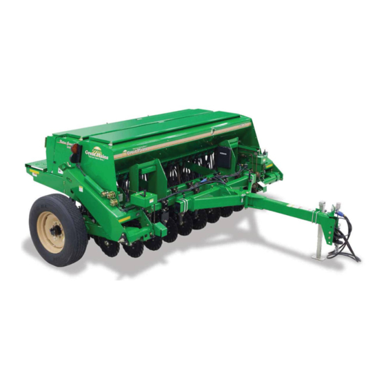
- Page 10 Description of Unit The 1206NT No-Till Drill is a 12' grain drill of end wheel design which couples Great Plains spring mounted coulter with a straight arm design of our solid stand opener to achieve no-till drilling capabilities.
- Page 11 For additional help with understanding these assembly instructions or for any other assembly or setup related questions, please contact our service department at the following address: Great Plains Service Department 1525 E. North St. P.O. Box 5060 Salina, KS 67402-5060 Or call us at (800) 270-9302 to speak over the phone with a service representative.
- Page 12 1206NT Table of Contents Preparation Step-by-step instructions for assembling the drill begin in the next section of the manual. Before commencing work, review the Tools Required and Pre-Assembly Checklist to make sure you have all necessary parts and equipment. The drill is shipped via flat bed truck. It is the dealer’s responsibility to unload the new machine.
- Page 13 1206NT Table of Contents Unloading the Truck Hoist drill from above. Do not fork-lift from beneath drill. There are no suitable lift points. Do not hoist via lugs after tongue is installed in the working position. Drill is not balanced at lugs with tongue installed.
- Page 14 1206NT Table of Contents Assembly The following headings are step-by-step instructions for assembling the drill. Begin with “Tools Required” and “Pre-Assembly Checklist” to make sure you have all necessary parts and equipment. Follow each step to make the job as quick and safe as possible and produce a properly working machine.
- Page 15 1206NT Table of Contents Assembly Removing Tongue, if Shipped Attached 1. Use hoist or lift to support the front of the drill while the tongue is being removed and installed. 2. Use hoist or lift to support the tongue (1).
- Page 16 1206NT Table of Contents Assembly Install Tongue The following instruction apply to both the standard and the folding tongue. 1. Remove the six mounting bolts and four U-bolts from the tongue. 2. Connect hoist lines (1) at available hitch holes (2), and around rear tongue tube (3), behind brace tubes (4).
- Page 17 1206NT Table of Contents Assembly Lighting and Hydraulic Hoses The hydraulic hoses are pre-installed on the drill and are tied to the hitch mounting plate. The lights may be assembled or may be shipped in the seed box or separately to prevent damage to the lighting system during transport and loading.
- Page 18 1206NT Table of Contents Assembly 6. Once hydraulic hoses are routed through the tongue, attach color-coded grips to the correct hydraulic hose. Retract grip and hose go to the rod end of the cylinder. Extend grip and hose go to the base end of the cylinder.
- Page 19 1206NT Table of Contents Setup Deferred Option Assembly Some optional drill features are not factory-installed, or may have been ordered for field installation. Although they are “assembly” items, they may require a hitched tractor, and/or that drill hydraulics be functioning (for drill lift/lower).
- Page 20 1206NT Table of Contents Setup Hitch Heights Clevis 24.0 in 21.0 in 61.0 cm 20.0 in 18.0 in 17.0 in 53.4 cm 50.8cm 14 in 45.7 cm 43.2 cm 35.6 cm Pintle 23.5 in 20.5 in 19.5 in 59.7 cm 17.5 in...
- Page 21 1206NT Table of Contents Setup Adjusting Either Hitch If the proposed hitch adjustment does not involve the hole used for the safety chain, skip step 2 and step 7. 1. Determine which tongue mounting holes and which hitch orientation provide the necessary height. See “Adjust Hitch Height”...
- Page 22 1206NT Table of Contents Setup Safety Chain Connect the safety chain around a suitable anchor location on the tractor. Take up enough chain slack so that no part of the safety chain touches the ground. Make sure there is enough chain slack for turning the tractor and the drill.
- Page 23 If an accident occurs, seek immediate medical attention from a physician familiar with this type of injury. Great Plains hydraulic hose connectors have color coded handle grips to help you hookup hoses to your tractor outlets. Hoses that go to the same remote valve are marked with the same color.
- Page 24 1206NT Table of Contents Setup Bleeding Hydraulics High Pressure Fluid Hazard: Relieve pressure before disconnecting hydraulic lines. Wear protective gloves and safety glasses or goggles when working with hydraulic systems. Escaping fluid under pressure can have sufficient pressure to penetrate the skin causing serious injury.
- Page 25 1206NT Table of Contents Setup Rephasing Cylinders The lift cylinders may, after a period of time, get out of time or phase. The effects of this can be seen when one side of the drill is running too low or too high because its lift cylinder is either over extended or not retracted compared to the other lift cylinder.
- Page 26 1206NT Table of Contents Appendix Tire Size and Pressure 295/75/R x 22.5”, 65 psi (4.5 bar) Torque Values Chart Bolt Head Identification Bolt Head Identification Bolt Bolt 10.9 Size Size Grade 2 Grade 5 Grade 8 Class 5.8 Class 8.8 Class 10.9...
- Page 27 1206NT Table of Contents Appendix Hydraulic Connectors and Torque Refer to Figure 127 (a hypothetical fitting) Leave any protective caps in place until immediately prior to making a connection. NPT - National Pipe Thread Note tapered threads, no cone/flare, and no O-ring. Apply liquid pipe sealant for hydraulic applications (do not use tape sealant, which can foul filters).
- Page 28 1206NT Table of Contents Appendix 2020-12-03 Table of Contents 150-166Q...
- Page 29 Table of Contents Table of Contents...
- Page 30 Great Plains, Mfg. 1525 E. North St. P.O. Box 5060 Salina, KS 67402...
Need help?
Do you have a question about the 1206NT and is the answer not in the manual?
Questions and answers