Qimarox PRORUNNER Mk5 User Manual
Hide thumbs
Also See for PRORUNNER Mk5:
- User manual (124 pages) ,
- User manual (90 pages) ,
- User manual (77 pages)
Table of Contents
Advertisement
Quick Links
Advertisement
Table of Contents

Related Manuals for Qimarox PRORUNNER Mk5


Summary of Contents for Qimarox PRORUNNER Mk5
- Page 1 User Manual PRORUNNER Mk5 Version1.2 / 26-06-2014...
- Page 2 The Netherlands Internet: www.Qimarox.com Copyright © Qimarox B.V. All rights reserved. No part of this publication may be reproduced, stored in a computer database or published in any form or in any way electronically, mechanically, by means of photocopying, recordings or in any manner without prior written permission from Qimarox.
-
Page 3: Table Of Contents
Table of contents About this manual Introduction..........................9 Product documentation ......................9 Source language ........................9 Symbols used in the manual ....................10 Terminology list ........................10 Further support and information ................... 11 General Machine identification ......................13 Machine layout drawing and specifications ................16 Warranty .......................... - Page 4 Horizontal transport ....................49 6.3.3 Vertical transport < 1400 kg ..................51 6.3.4 Vertical transport > 1400 kg ..................51 Preparations for a Qimarox supervised installation (optional) ..........52 Installing the machine......................52 6.5.1 Preparation....................... 52 6.5.2 Installing a pre-assembled machine................. 53 6.5.3...
- Page 5 7.7.1 How to measure the elongation on the chain ............64 7.7.2 How to tighten / loosen the chain ................65 Replace parts ........................66 7.8.1 Replace the trolley ....................66 7.8.2 Replace the wheel of the trolley ................71 7.8.3 Replace the product carrier ..................
- Page 6 10.2.3 Monthly maintenance ....................96 10.2.4 6-monthly maintenance .................... 96 10.3 Cleaning ..........................97 10.4 Check the slack on the driving drum bearings..............97 10.5 Replace parts ........................97 Maintenance gravity wheel conveyor 11.1 Specific safety regulations....................99 11.2 Preventive maintenance schedule, wheels of the gravity conveyor ........100 11.2.1 Daily maintenance....................
- Page 7 Exploded views of frame parts 15.1 Introduction......................... 121 15.2 Drive section........................122 15.2.1 Drive section parts list .................... 123 15.2.2 Drive section mounting materials ................124 15.3 Motor reductor section (option) ..................125 15.3.1 Motor reductor (option) section parts list ..............126 15.3.2 Motor reduction (option) section mounting materials ..........
- Page 8 16.9.2 Gravity wheel outfeed mounting materials ............. 173 Electrical circuit diagrams 17.1 Drives ..........................175 17.1.1 Lift drive type: SEW 3PH..................175 17.1.2 Lift drive type: Movimot ..................175 17.1.3 RollerDrive with DriveControl IP20................. 175 17.1.4 RollerDrive with DriveControl IP54................. 175 17.2 Signalling Column K ......................
-
Page 9: About This Manual
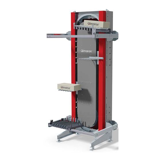
About this manual Introduction This manual provides information about the PRORUNNER Mk5 machine, that is used for the vertical movement of goods within a transport system. From here on in this manual, the PRORUNNER Mk5 is referred to as the “machine”. -
Page 10: Symbols Used In The Manual
To provide additional information to the user about a task or issue. A tip or point of attention for carrying out a task. Terminology list The table below explains common terms used by Qimarox for the machine. Term Definition supply conveyor The conveyor that delivers product to the infeed conveyor on the machine. -
Page 11: Further Support And Information
The outfeed conveyor puts products on the discharge conveyor. The out- feed conveyor is part of the machine. Further support and information Qimarox can supply additional expertise and support services, for: • Training • Global support •... - Page 12 About this manual UM-PRORUNNER_Mk5-1.2-EN-US...
-
Page 13: General
Serial number Order number Power supply Power (kW) PRORUNNER Mk5 Power (kW) conveyors Max. load (kg) per platform Max. load (kg) PRORUNNER Mk5 Weight PRORUNNER Mk5 (kg) Number of platforms Weight conveyors (kg) Nominal capacity (p/hour) : Total weight (kg) - Page 14 General Outfeed type: • Fixed outfeed conveyor • Bi-directional in- and outfeed conveyor • Pneumatic moveable outfeed conveyor • 3 Phase ~ motor moveable outfeed conveyor • Servo motor moveable outfeed conveyor Code Remark Possible Meaning of the value Type Refer to part value...
- Page 15 General Code Remark Possible Meaning of the value Type Refer to part value chapter Infeed drive type None / not supplied 24 VDC RollerDrive IP54 with DriveControl IP20 17.1 24 VDC RollerDrive IP54 with DriveControl IP54 17.1 3 Phase ~ 17.1 3 Phase ~ + TF 17.1...
-
Page 16: Machine Layout Drawing And Specifications
Inappropriate and/or modified use of the machine can result in dangerous safety issues and/or damage. You must obtain written confirmation from Qimarox before using the machine in a modified or unspecified manner. Qimarox cannot be held liable for any accidents and/or damages that may occur through inappropriate unauthorised use of the machine. -
Page 17: Warranty
The reader should consult Qimarox if errors are suspected. In no event shall Qimarox be liable for any damages arising out of or related to this user manual or the information contained in it.EXCEPT AS SPECIFIED HEREIN, QIMAROX MAKES... -
Page 18: Patent
General Patent Patent protection applies to parts of the machine. Consequently, other parties are not permitted to build this machine in this form, unless Qimarox B.V. has explicitly given permission for this. For further information about patents refer to mk5patents.Qimarox.com. -
Page 19: Safety
An electrical installer is only qualified if a person has attended appropriate training and/or attained appropriate industry standard recognized qualifications. Qimarox can provide training if required. Qimarox can also give advice about actions and tasks to be carried out on the machine. Safety instructions 3.3.1 General •... -
Page 20: Set Up
If changes and modifications are outside the scope of specifications given by Qimarox in this manual and Qimarox has not granted permission changes and modifications, then the changes and modifications will entirely be the responsibility of those persons responsible for carrying out the changes and modifications. - Page 21 Note Replace labels on the machine if they become unreadable or damaged. Qimarox requires a protection fenced area around the machine. Any access doors must be secured with (interlock) door switches. These switches must be included in the emergency stop and safety circuit. Refer to section 5.3 for information about how to set up the fenced area.
-
Page 22: Safety Symbols On The Machine
Safety Safety symbols on the machine Terminal 12 Nm UM-PRORUNNER_Mk5-1.2-EN-US... -
Page 23: Potential Risks
Switch off the machine. Potential risks The machine is intended to be integrated into a transport system. Qimarox has attempted to protect against as many hazards as possible. The following potential risks should be addressed before machine and assembled parts are put into operation: •... -
Page 24: Machine End Of Life And Environment Disposal
Sound level The sound level of the PRORUNNER Mk5 is 80.9 dB(A). To measure and calculate the sound level, refer to the standards ISO 3740 and ISO 3744. If necessary, you can ask Qimarox for a full report. -
Page 25: Description
Output conveyor (not supplied by Qimarox) Product carrier The PRORUNNER Mk5 is designed for the vertical transport of products. This vertical transport unit (or product lift) consists of a lift column, one or more product carriers and. depending on the purchased configuration, a dosing belt, output belt and shielding. - Page 26 Description The machine can consist of: • Mechanical construction. • Mechanical construction and electric sensors. • Mechanical construction, electric sensors and cabling to the terminal module. • Mechanical construction, electric sensors to the terminal module and a control box including control and software. UM-PRORUNNER_Mk5-1.2-EN-US...
-
Page 27: Motor
The infeed/outfeed conveyor may also have a motor fitted. For specifications, refer to the machine layout drawing. Working principle with fixed conveyors Supply conveyor sensor (not supplied by Qimarox) End of infeed conveyor sensor Product release sensor UM-PRORUNNER_Mk5-1.2-EN-US... -
Page 28: Product Infeed
The machine works according to a continuous principle in which the machine runs nonstop. However the machine can be used in start/stop mode. To set up the machine for start/stop mode you must consult Qimarox for the required specifications. The following sensors must be installed on the machine: Sensor... - Page 29 Description Preparing products for infeed to the machine Supply conveyor sensor End of infeed conveyor sensor Product The product is fed in onto the supply conveyor and monitored by sensor S1. The sensor is located on the end of the supply conveyor. The product (A) will wait at this position until the product release sensor B1 (not shown in this figure) sends a release signal to infeed the...
-
Page 30: Product Infeed Configurations
Description 4.2.2 Product infeed configurations There are various product infeed configurations that can be used, including mirrored configuration setups. Below are some examples. DANGER When the machine has 1 product carrier, the lift has a failure when: • There is a product on the outfeed conveyor AND •... -
Page 31: Product Transportation
Description Product infeed with 1 driven conveyor V2 > V1 4.2.3 Product transportation Chain system Product carrier The continuously circulating chain system (A) takes along one or more product carriers (B). These product carriers have a fork-like shape, allowing them to move between the infeed and outfeed conveyors. -
Page 32: Product Outfeed
Description Keeping the product carriers horizontal Rear side During transport, the product carriers are kept horizontal by a (patented) circulation system. Shaft Guide Wheels of the guide Guide bars The product carrier has been mounted to a shaft (A) that has been coupled to a guide (B) with 4 wheels (C). - Page 33 Description Monitoring of the passage of the product carrier Start time frame sensor Sensor for checking presence of product on the outfeed Sensor for checking if product has left the outfeed (on falling edge) Sensor B3 has been mounted into the machine.
-
Page 34: Specifications
When permitted weight and distance deviate from the specifications in the machine layout drawing, the machine must be adjusted to accommodate this. These type of adjustments may only carried out by Qimarox or after written permission from Qimarox has been obtained. -
Page 35: Specification Of Gap Between Conveyors
This calculation can be checked by Qimarox on request. 4.3.3... -
Page 36: Extra Support Of The Machine
4.3.4 Extra support of the machine The machine has to be supported with brackets (A) to the first floor or to other contruction if the heigth of the machine exceeds 4 meters. These brackets can be supplied by Qimarox. UM-PRORUNNER_Mk5-1.2-EN-US... -
Page 37: Machine Use Specifications
Description 4.3.5 Machine use specifications If Qimarox does not supply the product conveyors, the specifications below apply to the product conveyors. Specifications Value Maximum weight of infeed conveyor 75 kg Maximum weight of outfeed conveyor 75 kg Refer to the machine layout drawing for the correct specifications. - Page 38 Description UM-PRORUNNER_Mk5-1.2-EN-US...
-
Page 39: Application Information
Application information Application information The machine layout drawing gives application information for the machine. Layout options The machine can be set up in different configurations to work with the layout of the infeed and outfeed conveyors. This infeed and outfeed conveyor layout determines: •... -
Page 40: Driven Roller Conveyor
Application information Gravity wheel conveyor Tilting wheel conveyor The tilting wheel conveyor can be used to allow for infeed and outfeed at different levels. 5.2.2 Driven roller conveyor Make sure that the product carriers cannot touch anything during pickup and placement, as well as while they make their circular movement in the machine. - Page 41 Application information On 400 V with motor reductor On 24 V with drum motor On 24 V with drum motor Moveable roller conveyor to front side, electric UM-PRORUNNER_Mk5-1.2-EN-US...
- Page 42 Application information Moveable roller conveyor to front side, pneumatic Moveable roller conveyor to side, electric UM-PRORUNNER_Mk5-1.2-EN-US...
-
Page 43: Driven Belt Conveyor
Application information 5.2.3 Driven belt conveyor Make sure that the product carriers cannot touch anything during pickup and placement, as well as while they make their circular movement in the machine. A minimum distance of 5 mm is required between the moving and fixed parts. See the layout drawing for the pitch and the position of the fingers. -
Page 44: Fenced Area
Refer to 5.4.2. The maximum dimensions of the mesh of the fenced area is 40 x 40 mm (width x height). If Qimarox supplies the fenced area, the specifications will be included in the machine layout drawing. Control The control of the machine should be done from a central control system. -
Page 45: Safety Controls
Application information Sensors If the sensors are part of the delivery, they are connected to a central terminal box with cables. The central terminal box offers possibilities for connecting several sensors with M12 5-pole connections. Motor The motor can be connected directly or through an operating switch in the main power supply switch box. -
Page 46: Control Advice
Application information Check the circulation of the product carriers It is necessary to check the movement of the product carriers during normal operation by means of time monitoring in the software. When the time is exceeded, the machine must immediately stop to avoid damage. 5.4.3 Control advice The following are important points about the... -
Page 47: Installation
WARNING The machine should only be installed by qualified personnel. Unpacking Check the packing list when unpacking the machine. Immediately report damage or missing parts to Qimarox. Delivery The machine can be delivered pre-assembled or in parts. • A pre-assembled machine will be delivered in a horizontal position. - Page 48 Installation Machine pre-assembled Machine in two parts Machine in three or more parts UM-PRORUNNER_Mk5-1.2-EN-US...
-
Page 49: Transport
Installation Transport If the machine is delivered as a whole and in the horizontal position, it is packaged in cardboard. The forks of the fork-lift truck must be placed where cardboard has been applied (B). When the machine (A) is picked up at the places where cardboard has been applied, the centre of gravity is achieved. - Page 50 Installation Install the shaft (A) between the base plates (B). Transport Note This method of transport always applies when unloading the machine. Use a fork-lift truck for horizontal transport of the machine: Allowed pick-up points (A) indicated by the cardboard transport protection (B).
-
Page 51: Vertical Transport < 1400 Kg
Installation 6.3.3 Vertical transport < 1400 kg DANGER • The hoisting eyes (B) are suitable for a maximum weight of 1400 kg. Machines up to 7 - 8 m high can be moved using the hoisting eyes. • If the weight to be moved is more than 1400 kg, use a suitable lifting device (yoke). -
Page 52: Preparations For A Qimarox Supervised Installation (Optional)
All equipment listed below must be present before and during assembly. Indicate the contact person to whom Qimarox’s engineer must report when arriving or leaving before and after the assembly. This only applies when Qimarox supervises the assembly. -
Page 53: Installing A Pre-Assembled Machine
Anchor the machine (A). Note Use Fischer FBN II 12/100 bolts or equal. These are not by default delivered by Qimarox. See the bolts specifi- cations for information on the sup- plier. Disconnect the hoisting belt, the hoisting chain, or the yoke. -
Page 54: Installing A Machine Delivered In Parts
Installation 6.5.3 Installing a machine delivered in parts Set up the basis. Refer to section 6.5.2. Install the parts. Use the delivered coupling pieces (A, B, C, D). For the use of hoisting equipment refer to section 6.3.3 and 6.3.4. The machine can be installed from top to bottom (see 6.5.4) or from bottom to top (see 6.5.5). -
Page 55: Installing A Machine From Top To Bottom
Installation 6.5.4 Installing a machine from top to bottom Hoist up top section. Mount next section below top section. Hoist up and mount next section. Repeat step 3 until bottom section has been mounted. Mount the carriages and chain in bottom section. UM-PRORUNNER_Mk5-1.2-EN-US... -
Page 56: Installing A Machine From Bottom To Top
Installation Mount infeed and outfeed conveyors. 6.5.5 Installing a machine from bottom to top Place bottom section. DANGER • Fix the bottom section to the floor if the machine is installed in the final position • Support the machine during installation to prevent falling over if the machine is not in the final position Place next sections on top until top section has been placed. -
Page 57: Installing The Supply Conveyor
Procedure Determine the position of the conveyor to be installed. If the conveyor is supplied by Qimarox, the position can be found on the supplied drawings. If required, drill holes if the conveyor is to be installed outside the slotted holes already provided. - Page 58 Installation UM-PRORUNNER_Mk5-1.2-EN-US...
-
Page 59: Maintenance Vertical Conveyor
Adjust the maintenance frequency to the actual number of running hours per year. • If required, Qimarox can carry out the maintenance activities. Specific safety regulations For optimum functioning of the machine the various machine parts must be regularly maintained. -
Page 60: Preventive Maintenance Schedule, Machine Excluding The Carrier
Maintenance vertical conveyor Preventive maintenance schedule, machine excluding the carrier 7.2.1 Weekly maintenance during the first 8 weeks after putting into operation Item Task Action when required by the check Chain Tighten the chain. Refer to sec- tion 7.7. 7.2.2 Daily maintenance Item Task... -
Page 61: Monthly Maintenance
Maintenance vertical conveyor Item Task Action when required by the check Product carriers Check for damage. Replace the product carrier. Refer to section 7.8.3. Check if the fastening bolt on the carrying shaft is present and has been correctly fixed. Clean. -
Page 62: 6-Monthly Maintenance
Maintenance vertical conveyor Item Task Action when required by the check Clamping bush for drive Check if the socket screws are Tighten the socket screws to sprocket wheel fixed. the following torques: • shaft diameter ≤ 40 mm: 17 Nm •... -
Page 63: Cleaning
Switch off the machine. Secure the main power supply switch with a padlock. Remove deposit and dirt by hand. Report any damage to the technically responsible person or to Qimarox and make sure that any damage is remedied before restarting the machine. Lubrication 7.4.1... -
Page 64: Tighten/Slacken The Chain
Maintenance vertical conveyor Tighten/slacken the chain The chain will elongate by use. How fast this happens depends on the conditions of use. Chains elongate the most after the machine has been put into operation for the first time. • Too low chain tension results in the machine making a noise at the tensioning wheel and jerky product carrier movement. -
Page 65: How To Tighten / Loosen The Chain
Maintenance vertical conveyor 7.7.2 How to tighten / loosen the chain Remove the guard (A). Loosen the four bolts at the side of the tension block. Turn the tensioning bolt (A) to tighten or to 12 Nm slacken the chain: •... -
Page 66: Replace Parts
WARNING Replace parts only with parts supplied or recommended by Qimarox. If parts are not replaced with supplied or recommended Qimarox parts, the machine warranty becomes null and void. Refer to section 2.3. 7.8.1 Replace the trolley... - Page 67 Maintenance vertical conveyor Remove the product carrier (A). Remove the clamping ring (B) and the spacer (C). Remove the leveler (A) with the 4 wheels from the machine. WARNING Pay attention to ring (B). UM-PRORUNNER_Mk5-1.2-EN-US...
- Page 68 If the drive does not have a brake, the drive sprocket wheel must be clamped onto the frame. If the drive sprocket wheel can turn, this may cause injury. Therefore the auxiliary tool is required. You can order this auxiliary tool through Qimarox. Remove the guard (A). Note...
- Page 69 Maintenance vertical conveyor Uninstall the trolley - part 5 Remove the guard (A). Remove the curve plate (A). Remove the closing links (A, B, C) at both sides of the trolley. UM-PRORUNNER_Mk5-1.2-EN-US...
- Page 70 Maintenance vertical conveyor Remove the trolley (A). Uninstall the trolley - part 6 Check the parts for wear. Replace worn parts by new ones. Refer to section 7.8.2. Install the trolley Illustrations for installing: see the illustrations above for uninstalling. Place the trolley into the machine.
-
Page 71: Replace The Wheel Of The Trolley
Maintenance vertical conveyor 7.8.2 Replace the wheel of the trolley Remove the wheel Uninstall the trolley. Refer to section 7.8.1 and follow parts 1 - 5. Remove the locking ring (A). Remove the ring (B). Use a pulley puller to remove the wheel (C). -
Page 72: Replace The Slide Bearings Of The Leveler
Maintenance vertical conveyor Remove the bolt (B). Remove the product carrier (A). Install the product carrier Illustrations for installing: see the illustrations above for uninstalling. Install the product carrier. Before switching on the machine, move the product carrier to the upper sprocket wheel. - Page 73 Maintenance vertical conveyor Replace slide bearing - rear side Remove the leveler with the 4 wheels (A) from the machine. Remove the ring (B). WARNING Pay attention to ring (B). Remove the bearings (A) at front side and rear side. Install the guide Illustrations for installing: see the illustrations above for uninstalling.
-
Page 74: Replace The Wheel Of The Leveler
Maintenance vertical conveyor 7.8.5 Replace the wheel of the leveler Remove the guide. Refer to section 7.8.4. Loosen the bolt. Replace the wheel (A) of the leveler (B). Replace the bolt and tighten the bolt with a torque of 30 Nm. Note Pay attention to the torque. -
Page 75: Replace The Curve Plate - Upper Side
Maintenance vertical conveyor Install the curve plate Illustrations for installing: see the illustrations above for uninstalling. Install the curve plate. Install the side covers. 7.8.7 Replace the curve plate - upper side Uninstall the curve plate Remove the side covers (A). Remove the curve plate (A). -
Page 76: Replace The Chain
If the drive sprocket wheel can turn, this may cause injury. Therefore the auxiliary tool is required. You can order this auxiliary tool through www.Qimarox.com. • When replacing more than 1 chain section, lock the chain such that, from the top, it cannot fall. - Page 77 Maintenance vertical conveyor Uninstall a chain section - part 2 Slacken the chain by loosening the tensioning bolt. Refer to section 7.7.2. Remove the locking plates (C) on both sides of the chain. The end link (A) has been attached to the catch (B) by the locking plates.
-
Page 78: Replace The Sprocket Wheel - Tensioning Wheel
Maintenance vertical conveyor 7.8.9 Replace the sprocket wheel - tensioning wheel Also use this procedure for replacing the bearings of a sprocket wheel. Uninstall the sprocket wheel - part 1 Remove the trolley. Refer to section 7.8.1 and follow parts 1 - 5. Remove the chain section. -
Page 79: Replace The Sprocket Wheel - Drive Wheel
Maintenance vertical conveyor Install the sprocket wheel Illustrations for installing: see the illustrations above for uninstalling. Install the clamping ring and ring onto the sprocket wheel shaft. Install the sprocket wheel onto the shaft. Install the ring and the clamping ring onto the sprocket wheel shaft. - Page 80 Maintenance vertical conveyor Install the sprocket wheel Illustrations for installing: see the illustrations above for uninstalling. Install the sprocket wheel with clamping bush onto the shaft. Align the sprocket wheel. Use a ruler (A) to align the sprocket wheel with the side guides (B) of the chain.
-
Page 81: Replace The Drive - Helical Gear Unit
Before replacing the drive, the drive sprocket wheel must be clamped onto the frame. If the drive sprocket wheel can turn, this may cause injury. An auxiliary tool is required for this. You can order this auxiliary tool through Qimarox. See the illustration in the section 7.8.1. -
Page 82: Replace The Motor Reductor
Maintenance vertical conveyor 7.8.12 Replace the motor reductor Uninstall the motor reductor Remove the motor reductor (A) from the reactor bar (B). Remove the motor reductor (C) from the axle. Note Make sure that the key (D) does not fall. Uninstall the main shaft Remove the main shaft (A) from the bearing. - Page 83 Maintenance vertical conveyor Uninstall the bearings Remove the bearings (A) and plate washers (B). Install the motor reductor Illustrations for installing: see the illustrations above for uninstalling. Install the bearings and plate washers. Install the main shaft. Install the motor reductor. UM-PRORUNNER_Mk5-1.2-EN-US...
- Page 84 Maintenance vertical conveyor UM-PRORUNNER_Mk5-1.2-EN-US...
-
Page 85: Maintenance Rollerdrive Conveyor
Adjust the maintenance frequency to the actual number of running hours per year. • If required, Qimarox can carry out the maintenance activities. Specific safety regulations For optimum functioning of the machine the various machine parts must be regularly maintained. -
Page 86: Preventive Maintenance Schedule, Rollerdrive Conveyor
Maintenance RollerDrive conveyor Preventive maintenance schedule, RollerDrive conveyor 8.2.1 Daily maintenance Item Task Action when required by the check Guards and covers Check for visible damage. Replace damaged guards and / or covers. Check if the mounting materials Place the mounting materials or are present and have been cor- correct the way in which they rectly placed. -
Page 87: Monthly Maintenance
Maintenance RollerDrive conveyor 8.2.3 Monthly maintenance Item Task Action when required by the check Photocells Check for visible damage. Replace the photocell and the reflector if necessary. Refer to section 8.7. Check for loose parts. Fasten loose parts. Clean. Refer to section 8.3. Cabling Make sure that all cables are Connect the cables again if... -
Page 88: Cleaning
Secure the main power supply switch with a padlock. Remove deposit and dirt by hand. Report any damage to the technically responsible person or to Qimarox and make sure that any damage is remedied before restarting the machine. Check the drive roller Replace the drive roller if it is damaged or making running sounds. -
Page 89: Maintenance Belt Conveyor
Adjust the maintenance frequency to the actual number of running hours per year. • If required, Qimarox can carry out the maintenance activities. Specific safety regulations For optimum functioning of the machine the various machine parts must be regularly maintained. -
Page 90: Preventive Maintenance Schedule, Belt Carrier
Maintenance belt conveyor Preventive maintenance schedule, belt carrier 9.2.1 Daily maintenance Item Task Action when required by the check Guards and covers Check for visible damage. Replace damaged guards and / or covers. Check if the mounting materials Place the mounting materials or are present and have been cor- correct the way in which they rectly placed. -
Page 91: Monthly Maintenance
Maintenance belt conveyor 9.2.3 Monthly maintenance Item Task Action when required by the check Motor reductor Check the seals for leakage. Replace the seals. Follow the instructions in the Check for visible damage. Replace the damaged parts. manual of the manufacturer of Check for running sounds. -
Page 92: Cleaning
Switch off the machine. Secure the main power supply switch with a padlock. Remove deposit and dirt by hand. Report any damage to the technically responsible person or to Qimarox and make sure that any damage is remedied before restarting the machine. Lubrication 9.4.1... - Page 93 Maintenance belt conveyor WARNING Replace parts only with parts supplied or recommended by Qimarox. If parts are not replaced with supplied or recommended Qimarox parts, the machine warrantee becomes null and void. Refer to section 2.3. UM-PRORUNNER_Mk5-1.2-EN-US...
- Page 94 Maintenance belt conveyor UM-PRORUNNER_Mk5-1.2-EN-US...
-
Page 95: Maintenance Gravity Roller Conveyor
Adjust the maintenance frequency to the actual number of running hours per year. • If required, Qimarox can carry out the maintenance activities. 10.1 Specific safety regulations For optimum functioning of the machine the various machine parts must be regularly maintained. -
Page 96: Preventive Maintenance Schedule, Gravity Roller Conveyor
Maintenance gravity roller conveyor 10.2 Preventive maintenance schedule, gravity roller conveyor 10.2.1 Daily maintenance Item Task Action when required by the check Guards and covers Check for visible damage. Replace damaged guards and / or covers. Check if the mounting materials Place the mounting materials or are present and have been cor- correct the way in which they... -
Page 97: Cleaning
Switch off the machine. Secure the main power supply switch with a padlock. Remove deposit and dirt by hand. Report any damage to the technically responsible person or to Qimarox and make sure that any damage is remedied before restarting the machine. 10.4... - Page 98 Maintenance gravity roller conveyor UM-PRORUNNER_Mk5-1.2-EN-US...
-
Page 99: Maintenance Gravity Wheel Conveyor
Adjust the maintenance frequency to the actual number of running hours per year. • If required, Qimarox can carry out the maintenance activities. 11.1 Specific safety regulations For optimum functioning of the machine the various machine parts must be regularly maintained. -
Page 100: Preventive Maintenance Schedule, Wheels Of The Gravity Conveyor
Maintenance gravity wheel conveyor 11.2 Preventive maintenance schedule, wheels of the gravity conveyor 11.2.1 Daily maintenance Item Task Action when required by the check Guards and covers Check for visible damage. Replace damaged guards and / or covers. Check if the mounting materials Place the mounting materials or are present and have been cor- correct the way in which they... -
Page 101: 6-Monthly Maintenance
Maintenance gravity wheel conveyor 11.2.4 6-monthly maintenance Item Task Action when required by the check All bolt connections Check all bolt connections. Tighten bolts using the correct tool and torque. UM-PRORUNNER_Mk5-1.2-EN-US... -
Page 102: Cleaning
Switch off the machine. Secure the main power supply switch with a padlock. Remove deposit and dirt by hand. Report any damage to the technically responsible person or to Qimarox and make sure that any damage is remedied before restarting the machine. 11.4 Check the wheels for slack Replace the wheels in the wheel frame in case of abnormal sound or vibration. -
Page 103: Maintenance Driven Roller Conveyor
Adjust the maintenance frequency to the actual number of running hours per year. • If required, Qimarox can carry out the maintenance activities. 12.1 Specific safety regulations For optimum functioning of the machine the various machine parts must be regularly maintained. -
Page 104: Preventive Maintenance Schedule, Driven Roller Carriers
Maintenance driven roller conveyor 12.2 Preventive maintenance schedule, driven roller carriers 12.2.1 Weekly maintenance during the first 8 weeks after putting into operation Item Task Action when required by the check Conveyor belt Tighten the conveyor belt. Refer to section 12.9. 12.2.2 Daily maintenance Item... -
Page 105: Monthly Maintenance
Maintenance driven roller conveyor 12.2.4 Monthly maintenance Item Task Action when required by the check Motor reductor Check the seals for leakage. Replace the seals. Follow the instructions in the Check for visible damage. Replace the damaged parts. manual of the manufacturer of Check for running sounds. -
Page 106: Cleaning
Switch off the machine. Secure the main power supply switch with a padlock. Remove deposit and dirt by hand. Report any damage to the technically responsible person or to Qimarox and make sure that any damage is remedied before restarting the machine. 12.4 Lubrication 12.4.1... -
Page 107: Tightening/Loosening The Belt
Some machine parts are subject to wear. See the type plate and the exploded view for the specifications of the machine parts. WARNING Replace parts only with parts supplied or recommended by Qimarox. If parts are not replaced with supplied or recommended Qimarox parts, the machine warrantee becomes null and void. Refer to section 2.3. UM-PRORUNNER_Mk5-1.2-EN-US... - Page 108 Maintenance driven roller conveyor UM-PRORUNNER_Mk5-1.2-EN-US...
-
Page 109: Troubleshooting
Troubleshooting Troubleshooting 13.1 Vertical conveyor Problem Possible cause Solution Clamped product at conveyor Sensor defect. Go to manual control. Move the product carrier in the opposite direction to get the clamped product free. Remove the clamped product. The motor does not run. Electrical failure. - Page 110 Troubleshooting Problem Possible cause Solution The motor is overheated. The motor was designed for a Change the connection from tri- star connection but has been angle into star. connected in a triangle. Voltage and/or frequency devi- Connect the motor according to ates from the nominal value the data on the type plate.
- Page 111 Troubleshooting Problem Possible cause Solution The motor does not run. The operation or main power Set the operation/main power supply switch is on "OFF". supply switch to "ON". The door switch or emergency Make sure that the situation is stop is active. safe.
-
Page 112: Rollerdrive Conveyor
Troubleshooting 13.2 RollerDrive conveyor Problem Possible cause Solution The motor does not run. Electrical failure. Remedy the electrical failure. The operation or main power Set the operation/main power supply switch is on "OFF". supply switch to "ON". The door switch or emergency Release the emergency stop stop is active. - Page 113 Troubleshooting Problem Possible cause Solution The motor hums and does not The motor runs with 2 phases, Check the connections and the run properly. e.g. because of a faulty connec- cable. Dismount the motor for tion, broken cable or a defective repair.
- Page 114 Troubleshooting Problem Possible cause Solution Abnormal sounds, unusual Drive system clogged by dirt. Check the movement of the vibrations and swinging move- chain or drive belt and remove ments. dirt or deposit. Shorten the cleaning interval. Chains or drive belts are not Check if the drive shafts are running parallel.
-
Page 115: Belt Carrier
Investi- a humming sound". gate and remedy the cause of the increased use of energy. Transported product weight is Check maximum weight and above specifications. contact Qimarox to check if drive can be replaced with stronger version. UM-PRORUNNER_Mk5-1.2-EN-US... - Page 116 Troubleshooting Problem Possible cause Solution The motor overheats. The motor was designed for a Change the connection from star connection but has been triangle into star. connected in a triangle. Voltage and/or frequency devi- Connect the motor according to ates from the nominal value the data on the type plate.
-
Page 117: Gravity Roller Carrier
Troubleshooting Problem Possible cause Solution Use of energy (motor current) The drive belt has been ten- Lower the tension of the belt. too high and wear of drive belt. sioned too tightly. The drive belt does not run in Align the drive belt. line over the drive return wheels. -
Page 118: Error Signal On The Drivecontrol
Troubleshooting Problem Possible cause Solution DriveControl does not function No power supply. Check whether the output volt- or functions incorrectly. age of the power supply is within the specified voltage range. Inspect the connections and correct if necessary. Wrong position of the DIP Check and if necessary correct switches. -
Page 119: Ce Declaration Of Conformity
Technical Dossier for this machine and also declares that the machine: Name: PRORUNNER mk5 Function: Vertical transport Model/Type: Method of construction: according to layout drawing... - Page 120 CE declaration of conformity UM-PRORUNNER_Mk5-1.2-EN-US...
-
Page 121: Exploded Views Of Frame Parts
Exploded views of frame parts Exploded views of frame parts 15.1 Introduction The following pages show the exploded views, the parts lists and the mounting materials of the individual frame parts. UM-PRORUNNER_Mk5-1.2-EN-US... -
Page 122: Drive Section
Exploded views of frame parts 15.2 Drive section M8x16 (2x) M8 (2x) M8 (2x) M8 (4x) M8x25 (2x) M8x16 (4x) M8 (4x) M12x30 (8x) M8 (4x) M12x40 (8x) M12x45 (4x) M12 (8x) M8 (2x) M12 (8x) M8 (4x) M8x30 (2x) E/F/G M8x20 (2x) M8 (4x) -
Page 123: Drive Section Parts List
Exploded views of frame parts 15.2.1 Drive section parts list Drive section Package B-01 Item no. 1000143 Quan Item Description (parts) Notes tity number 100060 185 x 125 x 90 mm 1001346 Drive section L = 1475 mm 1001347 Drive section L = 1725 mm 1001348 Drive section... -
Page 124: Drive Section Mounting Materials
Exploded views of frame parts 15.2.2 Drive section mounting materials Drive section Package B-02 Item no.: 1000143 Quan- Article number Description (mounting mat.) Notes tity 1000148 Washer 1000174 Spring washer 1000172 Spring washer 1000175 Spring washer 1000149 Washer 1000050 Locknut 1000197 Hexagonal stud bolt M6 x 25... -
Page 125: Motor Reductor Section (Option)
Exploded views of frame parts 15.3 Motor reductor section (option) M16x70 (4x) M16 (4x) M16 (4x) M24 (1x) M10 (1x) M24x160 (1x) M24 (1x) M12x35 (6x) M12x35 (6x) M12 (6x) M12 (6x) UM-PRORUNNER_Mk5-1.2-EN-US... -
Page 126: Motor Reductor (Option) Section Parts List
Exploded views of frame parts 15.3.1 Motor reductor (option) section parts list Motor reductor section Package Item no. Quan Item Description (parts) Notes tity number 1001183 Moment arm support KA87 PRmk5 1001010 Nut plate moment arm KA87 PRmk5 1000976 Bearing block PASE 60N 1001007 Bearing block mounting Prmk5 1001008... -
Page 127: Tensioning Section 1/2
Exploded views of frame parts 15.4 Tensioning section 1/2 M10 (8x) M10 (8x) M10 (8x) M10x25 (8x) M6 (6x) M10x70 (8x) M6 (6x) M10x130 (8x) M6x25 (6x) M8x25 (6x) M8 (12x) M20x200 M8 (6x) M20 (1x) M10x25 (1x) M10 (1x) M8x16 (2x) M8 (2x) M12 (1x) -
Page 128: Tensioning Section Parts List 1/2
Exploded views of frame parts 15.4.1 Tensioning section parts list 1/2 Tensioning section Package A-01-1 Item no. 1000142 Quan- Item Description (parts) Notes tity number 1001606 600 x 350 x 120 mm 1000815 Tensioning section L = 1475 mm 1000818 Tensioning section L = 1725 mm 1000854... -
Page 129: Mounting Materials Tensioning Section 1/2
Exploded views of frame parts 15.4.2 Mounting materials tensioning section 1/2 Tensioning section Package A-02-1 Item no.: 1000142 Quantity Article number Description (mounting mat.) Notes 1000087 Hexagonal socket bolt M12 x 120 1000086 Hexagonal socket bolt M10 x 25 1000126 Hexagonal nut 1000206 Hexagonal nut... -
Page 130: Exploded View Tensioning Section 2/2
Exploded views of frame parts 15.4.3 Exploded view tensioning section 2/2 M8x20 (2x) M8 (4x) M8 (2x) M10 (8x) M10x30 (4x) M10 (8x) M10 (4x) M10 (8x) M10 (4x) M10 (4x) M6x16 (8x) M10 (4x) M10x20 (4x) M4 (3x) M4 (3x) M10 (8x) M4X16 (3x) M10x25 (8x) - Page 131 Exploded views of frame parts Tensioning section parts list 2/2 Tensioning section Package A-01-2 Item no. 1000142 Quan- Item Description (parts) Notes tity number 1000815 Tensioning section L = 1475 mm 1000818 Tensioning section L = 1725 mm 1000854 Tensioning section L = 1975 mm 1000103 Chain guide profile...
- Page 132 Exploded views of frame parts Mounting materials tensioning section 2/2 Tensioning section Package A-02-2 Item no.: 1000142 Quan- Article number Description (mounting mat.) Notes tity 1000134 Allen bolt M12 x 120 1000177 Hexagonal socket bolt M10 x 25 1000209 Hexagonal nut 1001175 Hexagonal nut 1000198...
-
Page 133: Centre Section
Exploded views of frame parts 15.5 Centre section M10 (8x) M10 (8x) M10x30 (4x) M10 (8x) M10 (4x) M10 (4x) M6 (6x) M8 (2x) M10 (4x) M6 (6x) M8 (4x) M8x20 (2x) M6x25 (6x) M10 (4x) M6x16 (8x) M10x20 (4x) M10x25 (8x) M10 (8x) M10x25 (8x) -
Page 134: Centre Section Parts List
Exploded views of frame parts 15.5.1 Centre section parts list Centre section Package C-01 Item no. 1000144 Quan Item Description (parts) Notes tity number 1001606 600 x 350 x 120 mm 1000800 Centre section L = 1250 mm 1000805 Centre section L = 1950 mm 1000810 Centre section... -
Page 135: Centre Section Mounting Materials
Exploded views of frame parts 15.5.2 Centre section mounting materials Centre section Package C-02 Item no.: 1000144 Quantity Article number Description (mounting mat.) Notes 1001606 600 x 350 x 120 mm 1000134 Pop rivet Al 6.4 x 12 1000197 Hexagonal stud bolt M6 x 25 1000148 Washer... -
Page 136: Assembly Sections
Exploded views of frame parts 15.6 Assembly sections M6x16 (4x) M6 (4x) M6x16 (8x) M6x16 (4x) M6 (4x) M6x16 (8x) M6x16 (4x) M6 (4x) M6x16 (8x) M12 (1x) M12x25 (1x) M12x25 (1x) M12 (1x) M12 (1x) M12x65 (1x) UM-PRORUNNER_Mk5-1.2-EN-US... -
Page 137: Assembly Section Parts List - 1
Exploded views of frame parts 15.6.1 Assembly section parts list - 1 Assembly Package C-01-1 Item no. 1000144 Article number Description (parts) Notes Drive section Tensioning section Centre section Trolley 1000097 Chain 1" 16B-1 7 links 1000702 Chain 1" 16B-1 1 link 1000154 Closing link 16B-1... -
Page 138: Assembly Section Parts List - 2
Exploded views of frame parts Assembly Package C-01-1 Item no. 1000144 Article number Description (parts) Notes 1001228 Gooseneck 150 mm 1001229 Gooseneck 100 mm 1001230 Gooseneck 75 mm 15.6.2 Assembly section parts list - 2 Assembly section - 2 Item no. 1000144 Article number Description (parts) Notes... - Page 139 Exploded views of frame parts Assembly section - 2 Item no. 1000144 Article number Description (parts) Notes 1001397 Cover PRmk5 rear 0.75 mm 789 x H 508, S235 SV RAL3020 1001398 Cover PRmk5 rear 0.75 mm 799 x H 521, S235 SV RAL3020 1001399 Cover PRmk5 rear 0.75 mm...
-
Page 140: Assembly Section Parts List - 3
Exploded views of frame parts Assembly section - 2 Item no. 1000144 Article number Description (parts) Notes 1001809 Cover PRmk5 rear 0.75 mm R77 793 x H 684, S235 SV RAL 9010 1000015 Cover PRmk5 front 8 mm sprocket 586 x H 758 plastic, grey 7036 1000963 Cover PRmk5 front 8 mm sprocket... - Page 141 Exploded views of frame parts Assembly section - 3 Item no. 1000144 Article number Description (parts) Notes 1000964 Cover PRmk5 front 8 mm A1250 586 x H 758 plastic, white 1000966 Cover PRmk5 front 8 mm S1725 586 x H 684 plastic, white 1001197 Cover PRmk5 front 8 mm 586 x H 677 plastic, grey...
-
Page 142: Assembly Sections Mounting Materials
Exploded views of frame parts Assembly section - 3 Item no. 1000144 Article number Description (parts) Notes 1000802 Cover PRmk5 side 0.8 mm L = 1250 steel RAL3020 1000807 Cover PRmk5 side 0.8 mm L = 1950 steel RAL3020 1000814 Cover PRmk5 side 0.8 mm L = 1350 steel, RAL3020 (shortened standard cover) -
Page 143: Guide
Exploded views of frame parts 15.7 Guide M12 (1x) M12x25 (1x) M12x40 (1x) M8 (4x) M8 / 10x30 (4x) UM-PRORUNNER_Mk5-1.2-EN-US... -
Page 144: Guide Parts List And Mounting Materials
Exploded views of frame parts 15.7.1 Guide parts list and mounting materials Guide Item no. Quan- Item Description (parts) Notes tity number 1000135 Guide PRmk5 galv. 1000190 Wheel PP 125x24/10-28G-SK 1000219 Fitted screw, steel (M8) ø10 x 30 1000220 Low hexagonal nut galv. 8 1000221 Spacer 1 mm steel ø10 * ø16... - Page 145 Exploded views of frame parts Guide stainless steel Item no. Quan- Item Description (parts) Notes tity number 1001222 Low hexagonal nut, stainless steel 1001225 Flat washer 1 mm, stainless steel 1000767 Clamp adjustment washer stainless ø30 steel 1000224 Spacer, stainless steel 0.5 mm ø35 * ø45 1001226 Hexagonal stud bolt, stainless steel...
-
Page 146: Trolley
Exploded views of frame parts 15.8 Trolley M6x12 (4x) M6 (4x) M8x16 (2x) M8 (2x) UM-PRORUNNER_Mk5-1.2-EN-US... -
Page 147: Trolley Parts List And Mounting Materials
Exploded views of frame parts 15.8.1 Trolley parts list and mounting materials Trolley Item no. Quan- Item Description (parts) Notes tity number 1000076 Frame trolley PRmk5 galv. 3 mm 1000043 Shaft trolley PRmk5 ø15 L = 81.4 mm 1000098 Trolley HD chain mounting 1000186 Spacer sleeve for closing link 1000672... - Page 148 Exploded views of frame parts Trolley HD Item no. Quan- Item Description (parts) Notes tity number 1000097 Chain 16B-1 RKK 7 link =177.8 mm 1000155 Closing link 16B-2 RKK 1000154 Closing link 16B-1 RKK 1000208 Hexagonal stud bolt 8.8 galv. M6 x 12 1000148 Flat washer galv.
-
Page 149: Exploded Views Of Product Conveyors
Exploded views of product conveyors Exploded views of product conveyors 16.1 Introduction The following pages show the exploded views, the parts lists and the mounting materials of the individual product conveyors. UM-PRORUNNER_Mk5-1.2-EN-US... -
Page 150: Rollerdrive Infeed
Exploded views of product conveyors 16.2 RollerDrive infeed M10 (2x) M10 (2x) M10x25 (2x) M8x16 (1x) M10x20 (2x) M8 (1x) M8x16 (1x) M10 (2x) M8 (1x) M5 (1x) M8x16 (7x) M8 (7x) M10x25 (2x) M5x10 (2x) M3x10 (2x) M3 (2x) M10 (2x) M10 (2x) M8 (1x) -
Page 151: Rollerdrive Infeed Parts List
Exploded views of product conveyors 16.2.1 RollerDrive infeed parts list Drive section Package B-01 Item no. 1003924 Quan Item Description (parts) Notes tity number 1003060 Conveyor bracket PRmk5 1003093 Basis conveyor frame PRmk5 1003072 Fastening reflector PRmk5 1002242 Reflector 1000968 ROL 50 ELVZ IL 560 1000707 RollerDrive EC310 16 : 1... -
Page 152: Rollerdrive Infeed Mounting Materials
Exploded views of product conveyors 16.2.2 RollerDrive infeed mounting materials Drive section Package B-02 Item no.: 1003931 Quan- Article number Description (mounting mat.) Notes tity 1000209 Hexagonal stud bolt 8.8Elvz M8 x 16 1002261 Hexagonal stud bolt 8.8Elvz M8 x 75 1000193 Hexagonal stud bolt 8.8Elvz M10 x 20... -
Page 153: Rollerdrive Outfeed
Exploded views of product conveyors 16.3 RollerDrive outfeed M10 (2x) M10 (2x) M10x25 (2x) M8 (1x) M10x20 (2x) M8x16 (1x) M10 (2x) M8x16 (7x) M8 (1x) M8 (7x) M8x16 (1x) M5 (1x) M5 (1x) M10x25 (2x) M5x10 (2x) M3x10 (2x) M3 (2x) M10 (2x) M10 (2x) -
Page 154: Rollerdrive Outfeed Parts List
Exploded views of product conveyors 16.3.1 RollerDrive outfeed parts list Drive section Package B-01 Item no. 1003924 Quan Item Description (parts) Notes tity number 1003060 Conveyor bracket PRmk5 1003093 Basis conveyor frame PRmk5 1003072 Fastening reflector PRmk5 1002242 Reflector 1000968 ROL 50 ELVZ IL 560 1000707 RollerDrive EC310 16 : 1... -
Page 155: Rollerdrive Outfeed Mounting Materials
Exploded views of product conveyors 16.3.2 RollerDrive outfeed mounting materials Drive section Package B-02 Item no.: 1003931 Quan- Article number Description (mounting mat.) Notes tity 1000209 Hexagonal stud bolt 8.8Elvz M8 x 16 1002261 Hexagonal stud bolt 8.8Elvz M8 x 75 1000193 Hexagonal stud bolt 8.8Elvz M10 x 20... -
Page 156: Gravity Roller Infeed
Exploded views of product conveyors 16.4 Gravity roller infeed M8 (1x) M5 (1x) M8x16 (1x) M3x10 (2x) M8x16 (2x) M8 (8x) M3 (2x) M8 (2x) M8x16 (8x) M10 (2x) M10 (2x) M8x16 (1x) M8 (1x) M10x20 (2x) M6x12 (1x) M10 (2x) M6 (1x) M8x16 (1x) M8 (1x) -
Page 157: Gravity Roller Infeed Parts List
Exploded views of product conveyors 16.4.1 Gravity roller infeed parts list Drive section Package B-01 Item no. 1003925 Quan Item Description (parts) Notes tity number 1003060 Conveyor bracket PRmk5 1003064 Arm t.b.v. rol PRmk5 1003072 Fastening reflector PRmk5 1002242 Reflector 1003106 ROL 40 KUN IL 500 1003065... -
Page 158: Gravity Roller Infeed Mounting Materials
Exploded views of product conveyors 16.4.2 Gravity roller infeed mounting materials Drive section Package B-02 Item no.: 1003999 Quan- Article number Description (mounting mat.) Notes tity 1000208 Hexagonal stud bolt 8.8Elvz M6 x 12 1000209 Hexagonal stud bolt 8.8Elvz M8 x 16 1001332 Hexagonal stud bolt 8.8Elvz M8 x 60... -
Page 159: Gravity Roller Outfeed
Exploded views of product conveyors 16.5 Gravity roller outfeed M5 (1x) M8 (1x) M8x16 (1x) M3x10 (2x) M8x16 (2x) M8 (8x) M3 (2x) M8 (2x) M8x16 (8x) M10 (2x) M8x16 (1x) M10 (2x) M8 (1x) M3 (2x) M10x20 (2x) M6x12 (1x) M10 (2x) M6 (1x) M8 (2x) -
Page 160: Gravity Roller Outfeed Parts List
Exploded views of product conveyors 16.5.1 Gravity roller outfeed parts list Drive section Package B-01 Item no. 1003926 Quan Item Description (parts) Notes tity number 1003060 Conveyor bracket PRmk5 1003064 Arm t.b.v. rol PRmk5 1003072 Fastening reflector PRmk5 1002242 Reflector 1003106 ROL 40 KUN IL 500 1003065... -
Page 161: Gravity Roller Outfeed Mounting Materials
Exploded views of product conveyors 16.5.2 Gravity roller outfeed mounting materials Drive section Package B-02 Item no.: 1003999 Quan- Article number Description (mounting mat.) Notes tity 1000208 Hexagonal stud bolt 8.8Elvz M6 x 12 1000209 Hexagonal stud bolt 8.8Elvz M8 x 16 1001332 Hexagonal stud bolt 8.8Elvz M8 x 60... -
Page 162: Multi Belt Infeed
Exploded views of product conveyors 16.6 Multi belt infeed M8 (2x) M10 (2x) M10x25 (2x) J28 (28x) J12 (56x) M10x20 (4x) M10 (4x) M6x12 (14x) M5 (2x) M6x12 (56x) 8x7x25 (3x) M10x25 (2x) M3x10 (2x) J28 (6x) M3 (2x) M10x25 (4x) M5x10 (3x) M10 (4x) M6 (4x) -
Page 163: Multi Belt Infeed Parts List
Exploded views of product conveyors 16.6.1 Multi belt infeed parts list Drive section Package B-01 Item no. 1003930 Quan Item Description (parts) Notes tity number 1003060 Conveyor bracket PRmk5 1003058 Support standard 1004269 Support MK5-XL 1004305 Conveyor supports PRmk5 400 1003087 Fastening photocell PRmk5 1002097... -
Page 164: Multi Belt Infeed Mounting Materials
Exploded views of product conveyors 16.6.2 Multi belt infeed mounting materials Drive section Package B-02 Item no.: 1004000 Quan- Article number Description (mounting mat.) Notes tity 1000897 Hexagonal stud bolt 8.8Elvz M6 x 20 1000209 Hexagonal stud bolt 8.8Elvz M8 x 16 1002261 Hexagonal stud bolt 8.8Elvz M8 x 75... -
Page 165: Multi Belt Outfeed
Exploded views of product conveyors 16.7 Multi belt outfeed M8 (2x) M10 (2x) M10x25 (2x) M10x20 (4x) M10 (4x) J12 (56x) J28 (28x) M5 (2x) 8x7x25 (3x) M6x12 (56x) M10x25 (2x) M3x10 (2x) J28 (6x) M3 (2x) M10x25 (4x) M3x10 (2x) M5x10 (3x) M3 (2x) M10 (4x) -
Page 166: Multi Belt Outfeed Parts List
Exploded views of product conveyors 16.7.1 Multi belt outfeed parts list Drive section Package B-01 Item no. 1003930 Quan Item Description (parts) Notes tity number 1003060 Conveyor bracket PRmk5 1003058 Support standard 1004269 Support MK5-XL 1004305 Conveyor supports PRmk5 400 1003087 Fastening photocell PRmk5 1002097... -
Page 167: Multi Belt Outfeed Mounting Materials
Exploded views of product conveyors 16.7.2 Multi belt outfeed mounting materials Drive section Package B-02 Item no.: 1004000 Quan- Article number Description (mounting mat.) Notes tity 1000897 Hexagonal stud bolt 8.8Elvz M6 x 20 1000209 Hexagonal stud bolt 8.8Elvz M8 x 16 1002261 Hexagonal stud bolt 8.8Elvz M8 x 75... -
Page 168: Gravity Wheel Infeed
Exploded views of product conveyors 16.8 Gravity wheel infeed M5x10 (21x) M10 (24x) M5 (21x) M10 (24x) M10x25 (2x) M10x20 (2x) M10 (2x) M8 (14x) M5 (2x) M8 (14x) M8x16 (14x) M10x25 (2x) M3x10 (2x) M3 (2x) M4x20 (1x) M4 (1x) M10 (2x) M8 (2x) M8 (2x) -
Page 169: Gravity Wheel Infeed Parts List
Exploded views of product conveyors 16.8.1 Gravity wheel infeed parts list Drive section Package B-01 Item no. 1003929 Quan Item Description (parts) Notes tity number 1003060 Conveyor bracket PRmk5 1003058 Support standard 1004269 Support MK5-XL 1004305 Conveyor supports PRmk5 400 1003087 Fastening photocell PRmk5 1002097... -
Page 170: Gravity Wheel Infeed Mounting Materials
Exploded views of product conveyors 16.8.2 Gravity wheel infeed mounting materials Drive section Package B-02 Item no.: 1004001 Quan- Article number Description (mounting mat.) Notes tity 1000209 Hexagonal stud bolt 8.8Elvz M8 x 16 1002261 Hexagonal stud bolt 8.8Elvz M8 x 75 1000193 Hexagonal stud bolt 8.8Elvz M10 x 20... -
Page 171: Gravity Wheel Outfeed
Exploded views of product conveyors 16.9 Gravity wheel outfeed M10 (24x) M10 (24x) M10x25 (2x) M5x10 (21x) M10x20 (2x) M5 (21x) M10 (2x) M5 (2x) M10x25 (2x) M5 (2x) M3x10 (2x) M3 (2x) M3x10 (2x) M3 (2x) M4x20 (1x) M4 (1x) M10 (2x) M8 (2x) M8 (2x) -
Page 172: Gravity Wheel Outfeed Parts List
Exploded views of product conveyors 16.9.1 Gravity wheel outfeed parts list Drive section Package B-01 Item no. 1003929 Quan Item Description (parts) Notes tity number 1003060 Conveyor bracket PRmk5 1003058 Support standard 1004269 Support MK5-XL 1004305 Conveyor supports PRmk5 400 1003087 Fastening photocell PRmk5 1002097... -
Page 173: Gravity Wheel Outfeed Mounting Materials
Exploded views of product conveyors 16.9.2 Gravity wheel outfeed mounting materials Drive section Package B-02 Item no.: 1004001 Quan- Article number Description (mounting mat.) Notes tity 1000209 Hexagonal stud bolt 8.8Elvz M8 x 16 1002261 Hexagonal stud bolt 8.8Elvz M8 x 75 1000193 Hexagonal stud bolt 8.8Elvz M10 x 20... - Page 174 Exploded views of product conveyors UM-PRORUNNER_Mk5-1.2-EN-US...
-
Page 175: Electrical Circuit Diagrams
Electrical circuit diagrams Electrical circuit diagrams 17.1 Drives 17.1.1 Lift drive type: SEW 3PH Connection main power: http://www.productliften.nl/media/text/240/247/680010306.pdf Connection TF: http://www.productliften.nl/media/text/240/247/681510306.pdf Connection BR: http://www.productliften.nl/media/text/240/247/69001006.pdf Other connection diagrams DR: http://www.productliften.nl/media/text/240/247/9pd0058us.pdf 17.1.2 Lift drive type: Movimot Connections Movimot: http://www.productliften.nl/media/text/240/247/17000017.pdf http://www.productliften.nl/media/text/240/247/16742419en.pdf 17.1.3 RollerDrive with DriveControl IP20 RollerDrive: http://www.productliften.nl/media/text/240/247/ec310_ip66.pdf DriveControl:... -
Page 176: Signalling Column K
Electrical circuit diagrams 17.2 Signalling Column K 17.2.1 Type KS IME18-08BPSZC0K =I1+IV/500.0 =U1+UV/500.0 4 2 3 1 4 2 3 1 4 2 3 1 4 2 3 1 EXTERN Spare Spare Spare Spare Spare Spare Spare Shift register Sensor (only with multiple in/outfeed) UM-PRORUNNER_Mk5-1.2-EN-US... - Page 177 Electrical circuit diagrams Position Name Amount Article number Discription Shift register 1000932 Inductive proximity switch, IME18- sensor 08BPSZC0K -B6-W1 1001601 Cable, PVC, 1 meter, M12 male 90° + M12 female 90°, 4-pole Connection unit 1 1003309 Exact12, 8-way, 5-pole, M12 UM-PRORUNNER_Mk5-1.2-EN-US...
- Page 178 Exact12, 8-voudig, 5-polig, M12 8000-88550-0000000 Murrelektronic Exact12 8xM12 5-p EXTERN RESERVE RESERVE RESERVE RESERVE RESERVE RESERVE RESERVE RESERVE AANSLUIT UNIT TAKT VORK PRORUNNER MK5 BENADERING BEVEILIGING /500.0 AANSLUIT UNIT PRORUNNER MK5 EXTERN RESERVE RESERVE RESERVE RESERVE RESERVE RESERVE RESERVE RESERVE UM-PRORUNNER_Mk5-1.2-EN-US...
- Page 179 Electrical circuit diagrams Position Name Amount Article number Discription Connection unit 1 1003309 Exact12, 8-way, 5-pole, M12 UM-PRORUNNER_Mk5-1.2-EN-US...
-
Page 180: Infeed Conveyors Ix
Electrical circuit diagrams 17.3 Infeed conveyors IX 17.3.1 Type IV C42-2 IME18-08BPSZC0K WL100-P4400 -U20 T-Coupler 5p Male M12 / 2x 4p Female M12 7000-41121-0000000 T-Coupler Murrelektronic =K+KS-U1 =K+KS/500.0 EXTERN Spare Spare End of infeed Product conveyor release UM-PRORUNNER_Mk5-1.2-EN-US... - Page 181 Electrical circuit diagrams Position Name Amount Article number Discription Product 1000932 Inductive proximity switch, IME18- release 08BPSZC0K -B1-W1 1001601 Cable, PVC, 1 meter, M12 male 90°+ M12 female 90°, 4-pole End of infeed 1002097 Photoelectric retro-reflex sensor, WL100- conveyor P4400 1002242 Reflector, C42-2 -B7-W1...
-
Page 182: Type Ib
Electrical circuit diagrams 17.3.2 Type IB C42-2 C42-2 WL100-P4400 WL100-P4400 IME18-08BPSZC0K IME18-08BPSZC0K -U20 T-Coupler 5p Male M12 / 2x 4p Female M12 7000-41121-0000000 Murrelektronic T-Coupler =K+KB-U1 =K+KB/500.0 Connection unit EXTERN XX XX End of infeed Product left Product release Start time frame conveyor outfeed / product... -
Page 183: Type Ip
Electrical circuit diagrams 17.3.3 Type IP C42-2 WL100-P4400 IME18-08BPSZC0K IME18-08BPSZC0K -B11 -U20 4 2 3 1 4 2 3 1 T-Coupler 5p Male M12 / 2x 4p Female M12 7000-41121-0000000 Murrelektronic T-Coupler 5 4 2 3 1 /501.0 4 2 3 1 4 2 3 1 4 2 3 1 4 2 3 1... - Page 184 Electrical circuit diagrams Position Name Amount Article number Discription Product release 1 1000932 Inductive proximity switch, IME18- 08BPSZC0K -B1-W1 1001601 Cable, PVC, 1 meter, M12 male 90°+ M12 female 90°, 4-pole End of infeed 1002097 Photoelectric retro-reflex sensor, WL100- conveyor P4400 1002242 Reflector, C42-2...
-
Page 185: Type Im
Electrical circuit diagrams 17.3.4 Type IM IME18-08BPSZC0K IME18-08BPSZC0K IME18-08BPSZC0K IME18-08BPSZC0K -B12 -B13 -B14 -B15 /500.0 EXTERN Connection Infeed out Spare Infeed out Spare Infeed out Spare Infeed out Spare unit infeed position position low position position low speed speed C42-2 WL100-P4400 IME18-08BPSZC0K IME18-08BPSZC0K... - Page 186 Electrical circuit diagrams Position Name Amount Article number Discription Product release 1 1000932 Inductive proximity switch, IME18- 08BPSZC0K -B1-W1 1001601 Cable, PVC, 1 meter, M12 male 90°+ M12 female 90°, 4-pole End of infeed 1002097 Photoelectric retro-reflex sensor, WL100- conveyor P4400 1002242 Reflector, C42-2...
-
Page 187: Type Is
Electrical circuit diagrams 17.3.5 Type IS C42-2 WL100-P4400 IME18-08BPSZC0K IME18-08BPSZC0K -B11 -U20 T-Coupler 5p Male M12 / 2x 4p Female M12 7000-41121-0000000 Murrelektronic T-Coupler /501.0 EXTERN XX XX End of Spare Product Spare Carrier Spare Spare Spare Connection infeed conveyor release past infeed unit infeed... - Page 188 Electrical circuit diagrams Position Name Amount Article number Discription Product release 1 1000932 Inductive proximity switch, IME18- 08BPSZC0K -B1-W1 1001601 Cable, PVC, 1 meter, M12 male 90°+ M12 female 90°, 4-pole End of infeed 1002097 Photoelectric retro-reflex sensor, WL100- conveyor P4400 1002242 Reflector, C42-2...
-
Page 189: Outfeed Conveyors (Ux)
Electrical circuit diagrams 17.4 Outfeed conveyors (UX) 17.4.1 Type UV C42-2 C42-2 IME18-08BPSZC0K WL100-P4400 WL100-P4400 -U21 T-Coupler 5p Male M12 / 2x 4p Female M12 7000-41121-0000000 Murrelektronic T-Coupler =K+KS-U1 =K+KS/500.0 EXTERN Spare Connection unit Start time Product Product frame on outfeed left outfeed UM-PRORUNNER_Mk5-1.2-EN-US... - Page 190 Electrical circuit diagrams Position Name Amount Article number Discription Start time frame 1 1000932 Inductive proximity switch, IME18- 08BPSZC0K -B3-W1 1001601 Cable, PVC, 1 meter, M12 male 90°+ M12 female 90°, 4-pole Product on out- 1002097 Photoelectric retro-reflex sensor, WL100- feed P4400 1002242...
-
Page 191: Type Ub
Electrical circuit diagrams 17.4.2 Type UB C42-2 C42-2 WL100-P4400 WL100-P4400 IME18-08BPSZC0K IME18-08BPSZC0K -U20 T-Coupler 5p Male M12 / 2x 4p Female M12 7000-41121-0000000 Murrelektronic T-Coupler =K+KB-U1 =K+KB/500.0 EXTERN Connection unit End of infeed Product left Product release Start time frame conveyor outfeed / product on outfeed... - Page 192 Electrical circuit diagrams 17.4.3 Type UP C42-2 C42-2 WL100-P4400 WL100-P4400 IME18-08BPSZC0K IME18-08BPSZC0K -B16 -U21 T-Coupler 5p Male M12 / 2x 4p Female M12 7000-41121-0000000 Murrelektronic T-Coupler /501.0 EXTERN XX XX Connection Product on Product left Spare Spare Time frame/ Spare Carrier past Spare unit outfeed...
- Page 193 Electrical circuit diagrams Position Name Amount Article number Discription Start time frame 1 1000932 Inductive proximity switch, IME18- 08BPSZC0K -B3-W1 1001601 Cable, PVC, 1 meter, M12 male 90°+ M12 female 90°, 4-pole Product on out- 1002097 Photoelectric retro-reflex sensor, WL100- feed P4400 1002242...
-
Page 194: Type Um
Electrical circuit diagrams 17.4.4 Type UM C42-2 C42-2 WL100-P4400 WL100-P4400 IME18-08BPSZC0K IME18-08BPSZC0K -B16 -U21 T-Coupler 5p Male M12 / 2x 4p Female M12 7000-41121-0000000 T-Coupler Murrelektronic /501.0 EXTERN XX XX Connection Product Product Spare Spare Time frame/ Spare Carrier Spare unit outfeed on outfeed Left outfeed... - Page 195 Electrical circuit diagrams Position Name Amount Article number Discription Start time frame 1 1000932 Inductive proximity switch, IME18- 08BPSZC0K -B3-W1 1001601 Cable, PVC, 1 meter, M12 male 90°+ M12 female 90°, 4-pole Product on out- 1002097 Photoelectric retro-reflex sensor, WL100- feed P4400 1002242...
-
Page 196: Type Us
Electrical circuit diagrams 17.4.5 Type US C42-2 C42-2 WL100-P4400 WL100-P4400 IME18-08BPSZC0K IME18-08BPSZC0K -B16 -U21 T-Coupler 5p Male M12 / 2x 4p Female M12 7000-41121-0000000 T-Coupler Murrelektronic /501.0 EXTERN XX XX Spare Spare Spare Spare Connection Product Product Time frame/ Carrier unit outfeed on outfeed left outfeed... - Page 197 Electrical circuit diagrams Position Name Amount Article number Discription Start time frame 1 1000932 Inductive proximity switch, IME18- 08BPSZC0K -B3-W1 1001601 Cable, PVC, 1 meter, M12 male 90°+ M12 female 90°, 4-pole Product on out- 1002097 Photoelectric retro-reflex sensor, WL100- feed P4400 1002242...
- Page 198 Electrical circuit diagrams UM-PRORUNNER_Mk5-1.2-EN-US...
-
Page 199: Assembly Instruction
Assembly instruction Assembly instruction 18.1 Assembly instruction Qimarox delivers the assembly instruction separately. UM-PRORUNNER_Mk5-1.2-EN-US... - Page 200 Assembly instruction UM-PRORUNNER_Mk5-1.2-EN-US...
-
Page 201: Appendix
Appendix Appendix 19.1 Product registration form Fill in this form and send it to support@qimarox.com for correct product registration. Machine type * Mk 1 Mk 5 Mk 9 Order number Qimarox Serial number Integrated by Order number integrator Installation date... - Page 202 Nobelstraat 43 3846 CE Harderwijk Tel: +31 341 436 700 Fax: +31 341 436 701 E-mail: info@Qimarox.com Internet: www.Qimarox.com...
Need help?
Do you have a question about the PRORUNNER Mk5 and is the answer not in the manual?
Questions and answers