Table of Contents
Advertisement
Quick Links
Advertisement
Table of Contents

Related Manuals for Qimarox Prorunner 12


Summary of Contents for Qimarox Prorunner 12
- Page 1 User Manual Prorunner 12 Version 2.1 - 09/02/2022...
- Page 2 All rights reserved. No part of this publication may be reproduced, stored in a computer database or published in any form or in any way electronically, mechanically, by means of photocopying, recordings or in any manner without prior written permission from Qimarox. UM Prorunner PR12 v2.1 EN...
-
Page 3: Table Of Contents
Delivery ......................... 24 Possible installations ..................... 24 Unpacking ........................25 Location ........................25 On-site transport ......................25 Preparations for a Qimarox installation (optional) ............26 Installing the machine ....................26 Maintenance Specific safety regulations ..................... 33 Preventive maintenance ....................33 Cleaning ........................ -
Page 4: About This Manual
1 About this manual Introduction This manual gives information about the vertical conveyor Prorunner 12. From here on, the Prorunner 12 is referred to as the 'machine'. The function of the machine is vertical movement of products or AGV’s within an automated transport system. -
Page 5: Symbols Used In The Manual
Area around the machine that unauthorized personnel cannot enter Fenced area for safety reasons. Transport Combination of machines that is used to transport products system Further support and information Qimarox can supply additional expertise and support services, for: • Training Global support • • Service contracts For more information please contact Qimarox. -
Page 6: General
General 2 General Machine identification The machine identification is given on the type plate. For the location, refer to Chapter 9. Refer to the Specifications document of the machine for the specifications and for the applicable products. Machine layout drawing and specifications After a machine order is placed, a Machine layout drawing and Specifications document is handed over for approval. -
Page 7: Warranty
The reader should consult Qimarox if errors are suspected. In no event shall Qimarox be liable for any damages arising out of or related to this user manual or the information contained in it. Except as specified herein, Qimarox makes no warranties, express or implied, and expressly disclaims any warranty of non-infringement, merchantability or fitness for a particular purpose. -
Page 8: Ce Declaration Of Conformity
General CE Declaration of Conformity The CE declaration can be found in the User manual of the complete system. This manual is provided by the system integrator. UM Prorunner PR12 v2.1 EN... -
Page 9: Safety
Before any person operates, sets up, electrically installs or maintains the machine, permission to carry out these tasks must be obtained from Qimarox. Qimarox determines if the person is qualified for carrying out the given task. The machine should only be operated by qualified personnel. -
Page 10: Safety Instructions
Safety Safety instructions General Comply with the safety regulations given in this manual. Deviation from these regulations • can lead to unacceptable risks. Never close doors (if present) in the fenced area of the machine, when a person is inside •... -
Page 11: Safety Provisions
If changes and modifications are outside the scope of specifications given by Qimarox in • this manual and Qimarox has not granted permission changes and modifications, then the changes and modifications will entirely be the responsibility of those persons responsible for carrying out the changes and modifications. - Page 12 All machines in the fenced off area must stop if the safety control system is triggered due to unsafe access. If Qimarox supplies the safety fencing, a layout drawing of the safety fencing will be provided. WARNING If the carrier moves the through a floor to another level, apply safety measures to all levels.
-
Page 13: Sound Level
Safety Sound level The A-weighted emission sound pressure level at workstations does not exceed 70dB(A). Note The sound pressure level applies to typical products and AGV’s. Different products or AGV’s can increase the sound level. Personal safety For your own safety use personal protective equipment. Always wear proper personal protective equipment when working with, on or near the machine. -
Page 14: Potential Risks
Potential risks The machine is intended to be integrated into a transport system. Qimarox has attempted to protect against as many hazards as possible. The following potential risks should be addressed before machine and assembled parts are... -
Page 15: Machine End Of Life And Disposal
Safety Machine end of life and disposal Proper use and maintenance of the machine will not involve any environmental risks. When the machine is no longer useable, the machine should be dismantled and disposed of in an environmentally responsible manner. WARNING Observe all relevant legislation, regulations, instructions and precautions with regard to health and safety when dismantling the machine. -
Page 16: Description
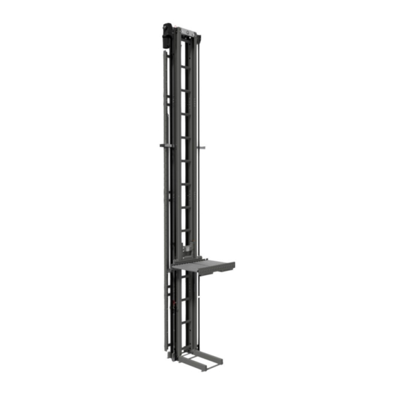
Description 4 Description The machine is designed to transport products or AGV’s vertically from one level to another. The machine must be installed as part of a larger transport system in which the products or AGV’s are automatically moved on and off the machine. General overview The machine consists of a column (A) on which a gearmotor (B) is mounted. -
Page 17: Working Principle
Description Working principle Reference procedure Before starting the machine make sure the machine is empty. When starting the machine, a reference procedure is needed. During this procedure the carrier moves down to the reference sensor. When this sensor detects the carrier, the resolver value is set and the machine is ready to run. -
Page 18: Sensors
Description Permission for movement Once the reference procedure is completed and stopping levels are programmed, the machine is ready to receive an product or AGV. Once the carrier is in position the product or AGV can move onto the platform. The product or AGV needs to be completely on the platform and preferably with its centre of gravity in the centre on the platform. - Page 19 Description Top limit switches (TCA-S1 & TCB-S1) The top limit switches prevent the carrier from moving out of its allowed range. When one of these limit switches is triggered, the machine must stop. Make sure that the limit switches give a signal when the lever is in the horizontal position. Resolver (TCA-E1 &...
- Page 20 Description Contour of carrier On the edges of the platform or carrier a photoelectric sensor with reflector monitors the transition from carrier to surroundings. If one of the sensors is covered an object is protruding and the carrier may not move. Top to bottom thru-beam (on request) The corners of each carrier are monitored by 4 thru- beam contour sensors.
- Page 21 Description Connection unit The sensors in the column are wired through the column to the connection units at the top (TCA & TCB) and bottom (BCA & BCB) of the column. TCB and BCB are only present when a carrier is mounted on two sides of the column.
-
Page 22: Motor
(please consult your frequency inverter supplier since it depends on the inverter brand). Control An example of the software is supplied by Qimarox. For information refer to the applicable software blocks and functional description. UM Prorunner PR12 v2.1 EN... -
Page 23: Specifications
Refer to the Machine layout drawing. When the specifications for the surrounding area deviate from the table above, the machine must be adjusted to this. Such adjustments shall always be carried out by Qimarox or after written permission from Qimarox. -
Page 24: Installation
Installation 5 Installation This chapter describes installation instructions. Refer to the user manual of the complete transport system for installation instructions of the machine within the transport system. WARNING The machine should only be installed by qualified personnel. Delivery The machine is delivered in segments. The carrier is lowered in the bottom frame and all parts will be packed on a pallet or in a crate for further assembly. -
Page 25: Unpacking
The combined lifting eyes and top plate are suitable for a maximum weight of 1000 kg. If the machine exceeds this weight, consult with Qimarox. Up to 5700 mm, a fully assembled machine can be tilted to the upright position. -
Page 26: Preparations For A Qimarox Installation (Optional)
The preparations given below will need to be done before Qimarox can assemble the machine on site. All equipment listed below must be present before and during assembly. 1. Indicate the contact person to whom the mechanic of Qimarox must report when arriving or leaving before and after the installation. - Page 27 Installation Installing the machine from top to bottom WARNING Do not work directly under the load. 1. Hoist the top section 2. Mount the coupling set to the top section Coupling set 3. Attach the next section below the top section 4.
- Page 28 Note Use Fischer FBN II 12/100 bolts or equal. These bolts are not provided by Qimarox. For the specifications of the bolts, see the information of the supplier, 11. Mount the lifting platform or product conveyor 12. Install the lateral support brackets if needed 13.
- Page 29 Installation Installing the machine from bottom to top WARNING Do not work directly under the load. 1. Place the bottom section 2. Make sure that the carrier is installed in the bottom section before connecting a next section 3. Mount the coupling set to the bottom section 4.
- Page 30 Note Use Fischer FBN II 12/100 bolts or equal. These bolts are not provided by Qimarox. For the specifications of the bolts, see the information of the supplier. 11. Mount the lifting platform or product conveyor 12. Install the lateral support brackets if needed 13.
- Page 31 Installation Tensioning the belts To ensure smooth running of the machine, the belts need to be tensioned correctly. The belt tensioners are located at both sides of the carrier. To tension one belt: 1. Loosen 2x M8 bolt (A) 2. Tension using tensioning M10 nut (B) while holding tensioning bolt (C) 3.
- Page 32 Installation Levelling the carrier When the belts are on the correct tension, check that the carrier is levelled. If the carrier is not levelled, this can be adjusted using the setting bolts at both sides of the carrier. To tension one belt: 1.
-
Page 33: Maintenance
Adjust the maintenance frequency to the actual number of running hours per year. If required, Qimarox can carry out the maintenance activities. Specific safety regulations For the proper functioning of the machine the various machine parts must be regularly maintained. - Page 34 Maintenance Weekly maintenance Item Definition Action when required Wheels of the Check for visible damage of the Replace the wheels. carrier running surface and bearings. Clean. Refer to section 6.3. Check for running sounds. Replace the wheels. Cabling Check the cables for visible Replace the cable(s).
-
Page 35: Cleaning
Secure the main power supply switch with a padlock. Remove deposit and dirt by hand. Report any damage to the technically responsible person or to Qimarox. Make sure that any damage is remedied before restarting the machine. UM Prorunner PR12 v2.1 EN... -
Page 36: Removing The Carrier
Maintenance Removing the carrier CAUTION Replace parts only with parts supplied or recommended by Qimarox. If parts are not replaced with supplied or recommended Qimarox parts, the warranty will become null and void. Make sure that the carrier is placed at the bottom of the column. - Page 37 Maintenance Carefully remove the 5x M8 bolts on each side of the carrier Once the middle plate has come loose, both the left and right side M8x16 of the carrier can be removed from the column. With the carrier removed inspect the wheels and other parts of the carrier If necessary replace parts of the carrier 10.
-
Page 38: Troubleshooting
Troubleshooting 7 Troubleshooting Problem Possible cause Solution The motor does not run. Electrical failure. Remedy the electrical failure. The operation or main switch Set the operation/main switch to is on "OFF". "ON". The door switch or emergency Release the emergency stop stop is active. - Page 39 Troubleshooting Too high use of energy. Check the weight of the load according to the data on the type plate. Check that the motor can move freely. The settings of the frequency Adjust the settings. inverter are incorrect. The motor hums and The power has been Connect the power in the does not run properly.
-
Page 40: Ce Declaration Of Conformity
CE declaration of conformity 8 CE declaration of conformity The CE declaration can be found in the User manual of the complete system. This manual is provided by the system integrator. UM Prorunner PR12 v2.1 EN... -
Page 41: Labels
Labels 9 Labels The same set of stickers is applied on the back side of the machine. UM Prorunner PR12 v2.1 EN... -
Page 42: Electrical Drawings
Inverter - MDX61B with encoder card resolver DER11B: https://download.sew-eurodrive.com/download/pdf/11697415.pdf Prefab cables: SB11 Brakemotor cable: 13354345 / 4x1.5mm2 + 2x1mm2 RH1M Resolver cable: 01994875 / 4x2x0.25mm2 + 2x0.5mm2 Note Use of other hardware will reduce the level of support Qimarox can provide. UM Prorunner PR12 v2.1 EN... - Page 43 Electrical drawings Nobelstraat 43 3846 CE Harderwijk Tel: +31 341 436 700 Fax: +31 341 436 701 E-mail: info@qimarox.com Internet: www.qimarox.com UM Prorunner PR12 v2.1 EN...
Need help?
Do you have a question about the Prorunner 12 and is the answer not in the manual?
Questions and answers