Table of Contents
Advertisement
Advertisement
Table of Contents

Related Manuals for Hytera DS-9300


Summary of Contents for Hytera DS-9300
- Page 1 User Manual...
- Page 2 Copyright Information Hytera is the trademark or registered trademark of Hytera Communications Corporation Limited (the Company) in PRC and/or other countries or areas. The Company retains the ownership of its trademarks and product names. All other trademarks and/or product names that may be used in this manual are properties of their respective owners.
- Page 3 FCC Statement This is A 90.219 CLASS A DEVICE. This equipment has been tested and found to comply with the limits for a Class B digital device, pursuant to part 15 of FCC Rules. These limits are designed to provide reasonable protection against harmful interference in a residential installation.
- Page 4 Compliance with RF Exposure Standards Hytera's radio complies with the following RF energy exposure standards and guidelines: général / Incontrôlée. United States Federal Communications Commission, Code of Federal Regulations; 47 CFR § 1.1307, 1.1310 and 2.1091 American National Standards Institute (ANSI) / Institute of Electrical and Electronic Engineers (IEEE) C95.
-
Page 5: Table Of Contents
User Manual Contents Contents Documentation Information ........................1 1. Introduction ............................3 1.1 Product Description ........................... 3 1.2 Highlights ............................3 1.3 System Architecture ........................... 3 1.3.1 Star Topology ........................... 4 1.3.2 Chain Topology ........................5 1.3.3 Ring Topology .......................... 5 1.3.4 Hybrid Topology ........................ - Page 6 Contents User Manual 5. Power On and Power Off ........................36 5.1 Powering On ............................ 36 5.2 Powering Off ............................ 36 6. Debugging ............................37 6.1 Preparation ............................37 6.2 Procedure ............................37 6.2.1 Querying Parameters ......................39 6.2.2 Setting Parameters ........................ 39 6.2.3 Upgrade ..........................
-
Page 7: Documentation Information
User Manual Documentation Information Documentation Information This section describes the audiences, conventions and revision history of this document. Intended Audience This document is intended to be read by: Sales engineers Common users Documentation Conventions Icon Conventions Icon Description Indicates information that can help you make better use of your product. - Page 8 Documentation Information User Manual Item Description Example folder names, and parameter values. Open "PDT_PSS.exe". Go to "D:/opt/local". In the Port text box, enter "22". Directs you to access a multi-level menu. Go to File > New. > For details about using the DWS, refer Denotes document titles.
-
Page 9: Introduction
SDR Technology. It supports multiple network topologies such as star, chain, ring and hybrid topologies. Effective mechanical design DS-9300 is compact and portable with effective heat dissipation and resistance to water, dust and salt spray. Various installation methods are available for DS-9300 including wall-mounting, pole-mounting and etc. -
Page 10: Star Topology
BS. The remote unit is installed away from the donor unit over a fiber link. The following figure shows the networking of DS-9300 and the Various topologies are available for networking between the donor and the remote units, including star, chain, ring and hybrid topologies. -
Page 11: Chain Topology
User Manual Introduction Remote Remote Remote Unit Unit Unit Remote Unit Donor Unit Donor Unit Remote Unit Remote Unit High Configuration For high configuration of star topology, each SFP port of the donor unit can connect to up to eight remote units, while one donor unit can connect to at most 16 remote units (N≤16). -
Page 12: Hybrid Topology
Introduction User Manual High Configuration For high configuration of ring topology, at most two rings can be formed on the donor unit, with each ring can connect to up to eight remote units (N≤8). 1.3.4 Hybrid Topology Low Configuration For low configuration of hybrid topology, each SFP port of the donor unit can connect up to four remote units, while one donor unit can connect to at most four remote units. - Page 13 User Manual Introduction Specifications Item Downlink Uplink 5 MHz (operating bandwidth) Channel Bandwidth 25 kHz Channel Capacity 1–8 Max. Output Power Cable-access: 45 Cable-access: 50 dB±3 dB±3 dB Max. Gain Wireless-access: 90 Wireless-access: 95 dB± 3 dB dB±3 dB Gain Adjustment Range/Step 30 dB/1 dB...
- Page 14 Introduction User Manual Specifications Item Downlink Uplink band edge ≤–40 dBc@RBW3 kHz 8 CH 75 kHz Carrier Spacing In-band ≤–45 dBc@RBW3 kHz Intermodulation 2 CH 75 kHz Carrier Spacing Attenuation Out-of-band (2.5 ≤–36 dBm/100 kHz@9 kHz to 1 GHz MHz away from the ≤–30 dBm/1 MHz@1 GHz to 12.75 GHz band edge)
- Page 15 User Manual Introduction Specifications Item Downlink Uplink Donor Unit: LC/UPC Fiber Connector Remote Unit: LC/UPC Power Supply Donor Unit /Remote Unit: 90 V to 264 V AC Cable-access: ≤30 W Donor Unit Power Wireless-access: ≤100 W Consumption Remote Unit ≤100 W ...
-
Page 16: Packing List
Packing List User Manual 2. Packing List Please unpack carefully and check that all items listed below are received. If any item is missing or damaged, please contact us or your dealer. Cable-access Donor Unit Item Qty. Item Qty. Main Unit Cable Kit Packing material for 19-inch Rack Optical Cable Kit... -
Page 17: Getting Started
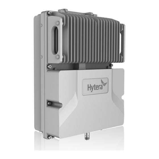
3. Getting Started Appearance DS-9300 adopts modular design. For the wireless-access donor unit and the remote unit, its LED indicators and connectors are provided on the front and rear panels of the rack. The following figure shows the appearance of the remote unit. -
Page 18: Donor Unit Interfaces
Getting Started User Manual Donor Unit Interfaces 3.2.1 Cable-access Donor Unit... -
Page 19: Wireless-Access Donor Unit
User Manual Getting Started 3.2.2 Wireless-access Donor Unit 3 12 13 14 Remote Unit Interfaces 7 8 9... -
Page 20: Interface Description
Getting Started User Manual Interface Description Label Meaning Connector Description LED indicators See "3.6". Single-pole-doubl POWER Power switch e-throw switch Modem antenna MANT SMA-F Reserved. connector ANT port of the Connected to the ANT port of the BS/TX duplexer, or TX duplexer, or connected to the TX port of port of the BS the BS if the duplexer does not exist. -
Page 21: Interface Definition
User Manual Getting Started Label Meaning Connector Description location change electric connector (generates an alarm upon illegal and door entry location change). Remote Unit: Monitors location change and the optical bypass switch. RF interface Connected to the donor antenna. RF interface Connected to the service antenna. -
Page 22: Led Indicators
Getting Started User Manual Pin No. Signal Name Definition Remarks Ground Pin No. Signal Name Definition Remarks Data transmission Output. Data receiving Input. Ground LED Indicators The LED indicators on the donor and the remote units indicate the running status. Color Status Description... - Page 23 User Manual Getting Started Color Status Description Indicator Flashing or off Optical synchronization error.
-
Page 24: Installation
Installation User Manual 4. Installation Safety Information Before performing any operation, read the following precautions and operation instructions carefully to ward off potential risks. Local Laws and Regulations When installing a device, comply with the local safety laws and regulations. Power Supply Danger Direct contact or indirect contact (through moist objects) with the high voltage or mains... -
Page 25: Installation Flow
Handle and use all devices and tools with care to avoid falling. Do not play or sleep on the aerial work platform. Personnel Installation and maintenance personnel must be trained to perform operations correctly and safely. Installation Flow Install DS-9300 device by following the installation flow below. Preparation... -
Page 26: Environment
Installation User Manual 4.3.1 Environment Space Requirements It is recommended that the space of at least 200 mm be left between the product top and the ceiling, and 500 mm between the product bottom and the ground. For product installed at its back, the space of at least 500 mm should be left at the right side, and 200 mm at the left side of product;... -
Page 27: Instruments And Tools
User Manual Installation The devices should be installed far away from electromagnetic interferences such as large electric devices. Outdoor Installation and Maintenance If the devices are installed outdoor, do not perform maintenance on extreme weathers such as storm, extreme temperature or high humidity. Grounding Requirements ... -
Page 28: Installation Parts
Installation User Manual 4.4.1 Installation Parts The following figure shows the parts needed for installation, including the auxiliary fixture, back panel, latches and M6 screws. Auxiliary Fixture Captive Screw Back Panel M6 Screw Bolt 4.4.2 Installing the Product Installation on Pole You can install the product at its back or at its left side. The pole diameter should be between 60 mm to 114 Installing at Back 1. - Page 29 User Manual Installation 4. Insert the back panel into the auxiliary fixture and tighten the captive fasteners on the back panel of the product. Installing at Left Side Installing the product at left side and installing the product at back are almost the same. The only difference is that the back panel is secured to the left side rather than back of the product.
- Page 30 Installation User Manual Installation on Wall You can install the product on a wall at the back or left side of the product. Installing at Back 1. Place the auxiliary fixture on the wall at the installation position and then mark the anchor points by using a marking pen.
- Page 31 User Manual Installation 4. Secure the back panel onto the back of the product using four M6 screws. 5. Insert the back panel into the auxiliary fixture and tighten the captive fasteners on the back panel of the product.
- Page 32 Installation User Manual Installing at Left Side Installing the product at left side and installing the product at back are almost the same. The only difference is that the back panel is secured to the left side rather than back of the product. The following figure shows the product installed at its left side.
-
Page 33: Cabling
User Manual Installation 4.4.3 Cabling Cabling Requirements Lay out cables according to requirements to reduce interference between them. Safety Requirements Lay out cables away from sharp objects or jagged walls, or protect cables using conduit. Lay out cables away from heat sources, or add heat-insulation materials between cables and heat sources. - Page 34 Installation User Manual Cover idle optical fiber connectors with protective caps. Cable List Cable-access Donor Unit Cable List One end (at DS-9300 device) Other end Cable Connector Connected to …… Connected to …… Grounding Ring Terminal Ground Terminal Grounding Bar...
- Page 35 User Manual Installation One end (at DS-9300 device) Other end Cable Connector Connected to …… Connected to …… Round Electric Power Cable AC Interfaces External Power Supply Connector Optical Fiber SFP/SFP+ CPRI 0–1 Interfaces Optical Fiber Network Monitoring 8-pin/1-pin Aviation...
- Page 36 Installation User Manual Wireless-access Donor Unit Remote Unit Installing the Grounding Cable 1. According to the route, make a grounding cable with proper length, and install ring terminals at both ends of the cable.
- Page 37 Installation The metal wires must be completely sealed, as shown in the figure below. 2. Connect one end of the cable to the ground connector at bottom of DS-9300 and the other end to the grounding bar. 3. Attach labels or tags to the installed cable.
- Page 38 Power cable delivered with DS-9300 device is 3*18 AWG cable. 1. Connect one end of the power cable to the PWR connector of DS-9300 device and the other end to the external power supply. Lay out the cable according to design requirements and fix the cable with cable ties.
- Page 39 Installation Procedure of installing the optical fiber is described as follows: 1. Connect the optical module to the SFP connector of DS-9300 device, as shown in the following figure. Note DS-9300 device adopts a dual-fiber single mode optical module with a transfer rate of 1.25 Gbps, a wavelength of 1,310 nm and a communication distance of 20 km.
-
Page 40: Post-Installation Check
Connectors of all cables are complete, intact, and tightly connected. The cables are not damaged or broken. Labels on cables, feeders and jumpers are clear and correct. 4.5.2 Checking the Device with Power On After the installation is complete, observe indicators on DS-9300 device to determine the system running status. - Page 41 User Manual Installation If the RUN indicator flashes green and the ALM indicator is off, the status of DS-9300 device is normal.
-
Page 42: Power On And Power Off
User Manual 5. Power On and Power Off Powering On Toggle the power switch on DS-9300 device to the ON position to power it on. Wait a few minutes and check the status of LED indicators. Powering Off Toggle the power switch on DS-9300 device to the OFF position to power it off. -
Page 43: Debugging
User Manual Debugging 6. Debugging Use the Product Support Software (PSS) to configure and upgrade the DS-9300 device. Preparation Before debugging, prepare the PSS tool, and connect the device to the computer. You can debug the device either locally through the cable or IP connection, or remotely through IP connection. The default IP address of the device is 192.168.1.100;... - Page 44 Debugging User Manual 2. Click Project, select DS_9300_CUSTOMER and click Lock. A message indicating locking database succeeded will appear in the message pane. 3. Select Ethernet tab, set the Destination and Port and click Connect. Note For debugging through the serial cable, select the Serial tab, set the Serial and Baudrate (115200) and click Connect.
-
Page 45: Querying Parameters
User Manual Debugging 6.2.1 Querying Parameters To manually query parameters of the selected device, click Query Parameter. If you click Auto Query, PSS will query all the parameters of the selected device every two seconds. In the Scan list, click on the device and check Select All. Click Query Parameter, the parameter values will be displayed in Status. - Page 46 Debugging User Manual Note For remote units, set the Downlink Output Under-power Threshold 10 dBm less than the actual output power in most cases. b. Select Real-time Sampling tab, and view the Downlink Input Power Level. The value of this parameter should be around -13 dBm for a cable-access donor unit, and -58 dBm for a wireless-access donor unit.
-
Page 47: Upgrade
User Manual Debugging d. Select the Alarm Status tab, and turn on all switches if a repeater management system (RMS) is configured. When an alarm is generated, it will be alerted in red font and needs handling. 2. Click Setting, the result will be displayed in the message pane. Note To restore the factory settings, click Factory Reset. -
Page 48: Exporting The Logs
Debugging User Manual Note If the upgrade fails or you want to roll back to the former version, perform the upgrade using the old upgrade file. 6.2.4 Exporting the Logs PSS allows you to export the operation logs. 1. In the Log area, click Path. 2. -
Page 49: System Maintenance
User Manual System Maintenance 7. System Maintenance Care and Cleaning To guarantee optimal performance as well as a long service life of the product, please follow the tips below. Caution Be sure to turn off the product before cleaning. Product Care ... -
Page 50: Alarm Handling
System Maintenance User Manual Regularly check and record the working status and main parameters such as receiving signal level, output noise level, and downlink output power. Check whether the coverage meets the requirements. Check whether the monitoring system works properly. ... -
Page 51: Troubleshooting
User Manual System Maintenance Alarm Information Solution downlink output power) Troubleshooting Phenomena Possible Cause Solution Connect the power cable The device fails to be The power cable is not connected, or the properly and ensure good powered on. contact with the socket is loose. contact. -
Page 52: Appendix: Parameters
Appendix: Parameters User Manual 8. Appendix: Parameters Take the donor unit as example. Device Information Parameter Configuration Remarks Electronic Serial Number Enter up to 10 characters, including digits Serial number of the device. (ESN) and letters. Monitor Version Keep the default value unchanged. Version of the monitor board. - Page 53 1 to 16. The range is 0 to 255. Manufacturer ID 1: Hytera 2: Reserved The range is 1 to 13. 1: DCCD 2: DCR 3: DICR ...
- Page 54 Appendix: Parameters User Manual Latitude or West Longitude. This parameter is subject to actual requirements. Device Latitude Negative number represents South Latitude or West Longitude. The range is 0 to 2. Communication Method for 1: SNMP Reporting Alarms 2: Reserved This parameter is subject to actual IP address of the RMS Monitor Monitor Center IP Address...
- Page 55 User Manual Appendix: Parameters Actual number of channels the Actual Number of Carriers The range is 0 to 32. device has opened. Downlink Input Power Level The range is –110 to 10. (dBm) Uplink Output Power Level The range is –110 to 50. (dBm) ...
- Page 56 Appendix: Parameters User Manual 1: Report Inspection Report 0: Do not report 1: Report Troubleshooting Report 0: Do not report 1: Report Configuration Change Report 0: Do not report Downlink PA Over-current The range is 0 to 65535. threshold Uplink/Downlink Squelch The range is –110 to 50.
- Page 57 User Manual Appendix: Parameters 0: Disable Channel Switch 1: Enable Alarm Status Parameter Configuration 0: Disable Master-Slave Monitoring Link Fault Alarm Enable 1: Enable 0: Disable Power Supply Disconnection Alarm Enable 1: Enable 0: Disable Power Supply Fault Alarm Enable ...
- Page 58 Appendix: Parameters User Manual 1: Enable 0: Normal Master-Slave Monitoring Link Fault Alarm 1: Fault 0: Normal Power Supply Disconnection Alarm 1: Fault 0: Normal Power Supply Fault Alarm 1: Fault 0: Normal Downlink Input Over-power Alarm ...
Need help?
Do you have a question about the DS-9300 and is the answer not in the manual?
Questions and answers