Table of Contents
Advertisement
Quick Links
Advertisement
Table of Contents

Related Manuals for Cobra IG20SI


Summary of Contents for Cobra IG20SI
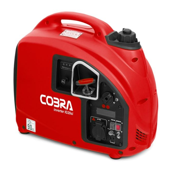
- Page 1 INVERTER GENERATOR USER MANUAL Model:IG20SI 4-Stroke Engine...
-
Page 2: Important Safety Notice
Correct and safe operation will guarantee your safety and extend the working life of generator. ● Cobra will continuously innovate and develop its products both in design and quality. The content of this manual may have minor difference from the updated product. Please contact your supplier for further support. - Page 3 CONTENT Hourmeter...
-
Page 4: Safety Information
1.SAFETY INFORMATION distance with constructions and other electrical appliances at least. • Place the generator on the leveled surface, in To ensure personal and property safety, please order to avoid overturning or spilling fuel. carefully read the following information. • Children and pets should be keep away the operation area. -
Page 5: Safety Label
SAFETY LABEL: <<05>>... - Page 6 2. SAFETY LABLE LOCATIONS <<06>>...
- Page 7 3. C OMPONENTS IDENTIFICATION CHOKE KNOB SPARK PLUG FUEL CAP MAINTENANCE VENT LEVER COVER MUFFLER FUEL CAP CONTROL PANEL STARTER GRIP AIR CLEANER MAINTENANCE COVER FUEL SWITCH ECON. SW ENGINE SWITCH <<07>>...
-
Page 8: Control Panel
3.1) Control Panel 3.2) ECON. SW (Economy control switch): “ON”( • When the economy control switch is turned to “ON”( ),the engine keeps running at idle state automatically when the electrical appliance is disconnected,and it will return to the proper speed with the requirement of electrical load. - Page 9 NOTE will be off, and output indicator light (green) • When a high load electrical appliance is will be on. connected instantaneously, in order to reduce • Under the non-overloading condition, the voltage change, turn the economy control switch "RESET" is supposed to be ineffective. to the ( )position.
-
Page 10: Pre-Operation Check
4. PRE- OPERATION CHECK NOTE • Using non-detergent or 2-stroke oil could shorten the engine’s working life. • Using the high quality engine oil with strong WARNING detergents Be sure the generator is on the leveled surface and • Using 4-stroke engine oil, certified to meet or the generator is stopped. -
Page 11: Check F Uel Level
FUEL CAP NOTE OPEN UPPER LIMIT MARK • Before the engine oil reduces below the safety margin, low oil alert system will close the engine automatically The oil alert indicator light red will be on. • To avoid the inconvenience caused by unexpected stopping,it is still advisable to Fuel Capacity: 3.6L check the engine oil level regularly. -
Page 12: Check Air Cleaner
4.3) Check Air Cleaner Check the air cleaner element to be sure it is clean AIR CLEANER ELEMENT and in good condition. a.Loosen three screws of the air cleaner AIR CLEANER maintenance cover, and remove the cover. COVER COVER SCREW COVER SCREW COVER SCREW c. -
Page 13: Starting The Engine
5. STARTING THE ENGINE NOTE When transporting generator, turn the fuel cap vent lever to the position. “OFF” NOTE 5.2) Turn fuel switch to the position. “ON” Before starting engine, disconnect load with receptacle. FUEL SWITCH 5.1) Turn the fuel cap vent lever to the “ON”... -
Page 14: Starter Grip
5.4) Pull the choke knob fully out. STARTER GRIP CHOKE KNOB NOTE NOTE Return the starter grip slowly by hand. Do not make Do not pull out the choke knob, when engine is hot or the starter grip spring back quickly. ambient temperature is high. - Page 15 1000 meters contact an authorized Cobra service CHOKE KNOB dealer to modify the carburetor. Generator output power should be modified according to the altitude and ambient temperature. The correction factor refers to 13.2 WARNING If the carburetor has been modified for high altitude operation, the air-fuel mixture will be too lean for low altitude use.
-
Page 16: Generator Use
6. GENERATOR USE WARNING • For continuous operation, do not exceed the rated out-put power of generator. WARNING • Do not make parallel connection with other generators. • Be sure to ground the generator when the • Do not connect an extension to the exhaust pipe. connected electrical appliance is grounded. -
Page 17: Charging Cable
6.1) DC Application The DC receptacle, 15-30V under no load condition, may be used for charging 12V battery only. NOTE In DC operation, turn the to the ECON SW “OFF” ( ) position. 6.1.1) Disconnect the vehicle battery ground cable CHARGING CABLE from the negative battery terminals. - Page 18 circuit protector, remove load firstly, and 4)Reconnect the vehicle battery ground cable. then reset the protector after a few minutes. WARNING • The battery can release the explosive gases • Keep the battery away from spark/fire. Charge RECEPTACLE the battery in ventilated condition. •...
-
Page 19: Overload Indicator Light(Red)
OUTPUT INDICATOR indicator light (red) is on. The AC power will be LIGHT (GREEN) switched off, but engine is still running. If the overload indicator light (red) is on, disconnect the electrical appliances firstly, press and hold the rest button 1s. If the overload indicator light (red) is OFF and the output indicator light (green) is on, reconnect the electrical appliances. -
Page 20: Oil Alert System
7. STOPPING THE ENGINE 6.4) Oil alert system The oil alert system is designed to prevent engine To stop the engine in an damage caused by an insufficient amount of oil emergency, turn the engine in the crankcase. Before the oil level in the switch to the position. - Page 21 7.3) Turn the fuel switch to the position. NOTE “OFF” Be sure the fuel cap vent lever and engine switch locate the “OFF” position, when stopping, transporting and storing the generator. FUEL SWITCH 7.4) Turn the fuel cap vent lever to the “OFF” position.
-
Page 22: Maintenance
If the engine must run, be sure the dealer, unless you have the proper tools and are area is well ventilated. The exhaust contains mechanically proficient. Refer to Cobra manual for poisonous carbon monoxide gas. service procedures. Use genuine Cobra or equivalent quality (3) For commercial use, long hours of operation to components to replace the wear components. -
Page 23: Air Cleaner Service
OIL POT 8.1.3) Drain dirty oil into a container thoroughly. 8.1.4) Refill the recommended oil and check the oil OIL FILLER level. UPPER LEVEL 8.1.5) Reinstall the oil filler cap. 8.1.6) Reinstall the maintenance cover and tighten Oil Capacity: 0.41L the cover screws. - Page 24 WARNING Do not use Petrol or low ignition point solvents for AIR CLEANER ELEMENT cleaning. They are flammable and explosive under certain conditions. AIR CLEANER COVER NOTE Never run the generator without the air cleaner, rapid damage to the engine will occur. 8.2.1) Loosen three screws of the air cleaner maintenance cover, and remove the cover.
-
Page 25: Spark Plug Service
HANDLE BAR 8.2.5)Reinstall the air cleaner element and cover. 8.2.6)Reinstall the maintenance cover, and tighten SPARK PLUG CAP the screws. 8.3) Spark Plug Service Recommendation spark plug: E6RTC Check the spark plug gap and clean the carbon deposition at the bottom of the spark plug. 8.3.1) Remove the spark plug maintenance cover 8.3.4) Take off the spark plug with the spark plug SPARK PLUG... -
Page 26: Spark Arrester Maintenance
8.4) Spark Arrester Maintenance 8.3.6) Measure the spark plug gap with a feeler WARNING gauge. The normal value:0.6-0.7mm(0.024- 0.028in). Adjust the gap by bend one of the The spark arrester must be maintained every electrode carefully. 100h service. 8.3.7) Reinstall the spark plug carefully, by hand, 8.4.1)Remove the six screws, and remove the to avoid cross-threading. - Page 27 8.4.2)Take off the spark arrester from the muffle 8.4.4)Reinstall the spark arrester and muffle after the engine cool down. guard. 8.4.3)Use a brush to remove carbon deposits from the spark arrester . If the spark arrester is wear, replace it. <<27>>...
- Page 28 9.TRANSPORTING/STORING Storing for a long period: 9.1) Make sure the storage area without excessive humidity and dust. 9.2) Drain off the fuel. Avoid fuel spilling during transporting or temporary storing, both the engine switch and the fuel cap vent lever should turn to “OFF’ position, WARNING and the generator should place in normal operating position.
- Page 29 STARTER GRIP b. Turn the engine switch to “ON” position, and loosen the carburetor drain screw to discharge Petrol inside of carburetor. 9.3) Change the engine oil. 9.4) Remove the spark plug, and pour a tablespoon of clean engine oil(10~20ml)into the cylinder.
-
Page 30: Troubleshooting
Is the DC circuit Push the DC circuit Replace it if necessary protector OFF? protector ON. If the engine still does not start, contact with an Contact with an authorized Cobra dealer authorized Cobra dealer <<30>>... -
Page 31: Technical Specifications
11. TECHNICAL SPECIFICATIONS Specifications Parameters DC Output 12V/5A Model Fuel Tank Volume 3.6L DJ148F 4-stroke, overhead valve, Continuous Running Time 3.9h Type single cylinder, forced-air cooling Fuel Consumption 550g/kW.h Engine Displacement 79cm Bore*Stroke Working Ambient Temperature -20 ~40 48.6mm*43.0mm Compression Ratio Max. - Page 32 Hourmeter To Reset Aux. Winding DC Receptacle Receptacle Main Winding Stepter Motor ECON.SW Reset Spark plug Generator Engine Switch Ignition Sensor <<32>>...
- Page 33 13. APPENDIX NOTE: Relative humidity 60% correction factorC- 13.1) Environment Correction 0.01; The standard condition of rated power output: Relative humidity 80% correction factorC - 0.02; Altitude:0m Relative humidity 90% correction factorC- 0.03; Ambient temperature:25 C Relative humidity 100% correctionfactorC- Relative humidity:30% 0.04;...
- Page 34 13.2) Noise and Access Noise emission measure according to ISO 8528-10, EN ISO 3744, European Directive 2000/14/EC with amendment 2005/88/EC Model of generator set: IG20SI Sound Pressure Level: 68 dB(A) Guaranteed Sound Power Lever 90dB(A) Measurement Uncertainty K: 1.7 dB(A) The quoted figures are emission levels and are not necessarily safe working levels.
-
Page 35: Ec Declaration Of Conformity
EC DECLARATION OF CONFORMITY We herewith declare, Cobra Garden Machinery Henton & Chattell Ltd, London Road, Nottingham NG2 3HW United Kingdom that the following machine complies with the appropriate basic safety and health requirements of the EC Directive based on its design and type, as brought into circulation by us. -
Page 36: Consumer Information
Please contact your retailer for any service related issues in the first instance. As appropriate you may be referred to another Cobra dealer who is professionally trained to complete service work as necessary. The Cobra dealer list is available at cobragarden.co.uk or contact 0115 986 2161 for assistance. - Page 37 Cobra Garden Machinery Henton and Chattell Ltd, London Road, Nottingham NG2 3HW UK...
Need help?
Do you have a question about the IG20SI and is the answer not in the manual?
Questions and answers