
Related Manuals for Generac Power Systems Magnum MLT3060M


Summary of Contents for Generac Power Systems Magnum MLT3060M
- Page 1 Owner’s Manual Light Tower MLT3060M • MLT3060K 000000 For technical assistance contact: www.generacmobileproducts.com Technical Support 1-800-926-9768 SAVE THIS MANUAL FOR FUTURE REFERENCE...
- Page 2 Use this page to record important information about your Light Tower Record the information found on your unit data label on this page. See unit serial number location (Unit Serial Unit Model Number Number Locations). The label plate is affixed to the inside partition, to the left of the control panel console.
-
Page 3: Table Of Contents
Table of Contents Section 1: Safety Rules & General Prestart Checklist ..........26 Information Raising the Mast ..........26 Introduction ............1 Starting the Unit ..........27 Read This Manual Thoroughly ........1 Preparing for Start-Up (with PowerZone How to Obtain Service ..........1 Controller, If Equipped) ........ - Page 4 Table of Contents Jack Maintenance ..........38 Trailer Wheel Bearings ........38 Section 5: Troubleshooting General Troubleshooting ........39 Troubleshooting the Lights ......40 Section 6: Wiring Diagrams Mast Junction Box Wiring and Light Connections ............41 AC Wiring ............42 DC Wiring—MLT3060M ........43 DC Wiring—MLT3060K ........44 DC Wiring for Optional Equipment ....45 Trailer Wiring ............46 Owner’s Manual for MLT3060M-K Light Tower...
-
Page 5: Section 1: Safety Rules & General Information
Safety Rules & General Information Section 1: Safety Rules & General Information Introduction Safety Rules Thank you for purchasing a Generac Mobile Products LLC The manufacturer cannot anticipate every possible product. This unit has been designed to provide high circumstance that might involve a hazard. The warnings in performance, efficient operation, and years of use when this manual, and on tags and decals affixed to the unit are, maintained properly. -
Page 6: General Hazards
Safety Rules & General Information General Hazards Explosion and Fire Hazards DANGER DANGER Asphyxiation. Running engines produce Explosion and Fire. Fuel and vapors are carbon monoxide, a colorless, odorless, extremely flammable and explosive. Add fuel poisonous gas. Carbon monoxide, if not in a well ventilated area. -
Page 7: Electrical Hazards
Safety Rules & General Information Electrical Hazards Battery Hazards DANGER DANGER Electrocution. In the event of electrical accident, Electrocution. Do not wear jewelry while immediately shut power OFF. Use non-conductive working on this equipment. Doing so will implements to free victim from live conductor. Apply result in death or serious injury. -
Page 8: Fuel Hazards
Safety Rules & General Information Fuel Hazards Operating Safety DANGER Positioning the Unit Explosion and fire.Fuel and vapors are extremely DANGER flammable and explosive. No leakage of fuel is permitted. Keep fire and spark away. Failure to do High Voltage. Verify area above unit is clear of overhead wires and obstructions. -
Page 9: Raising And Lowering The Mast
Safety Rules & General Information Service Safety Raising and Lowering the Mast WARNING This unit uses high voltage circuits capable of causing serious injury or death. Only a qualified and licensed Electrocution. Do not set up or operate electrician should troubleshoot or repair problems this unit if severe weather is expected. -
Page 10: Towing Safety
Safety Rules & General Information Towing Safety Reporting Trailer Safety Defects Towing a trailer requires care. Both the trailer and vehicle If you believe your trailer has a defect which could cause must be in good condition and securely fastened to each a crash or could cause injury or death, you should other to reduce the possibility of an accident. -
Page 11: Safety And Operating Decals
Safety Rules & General Information Safety and Operating Decals Danger–Diesel Fuel, Asphyxiation, No Open Flame Figure 1-1 through Figure 1-4. This unit features Ultra Low Sulfur Fuel Only numerous safety and operating decals. These decals Grounding Stud provide important operating instructions and warn of dangers and hazards. - Page 12 Safety Rules & General Information WARNING STAND CLEAR OF FRONT AND REAR OF MACHINE WHEN MAST IS BEING TILTED UP OR DOWN. WARNUNG AUFENTHALT INVORDERER ODER HINTERER UMGEBUNG DES GERÄTES VERMEIDEN WÄHREND MAST HOCH ODER NIEDER GESCHWENKT WIRD. ADVERTENCIA MANTENGASE ALEJADO DE LA PARTE DELANTERA O TRASERA DE LA MAQUINA MIENTRAS QUE SE ESTA PROCEDIENDO A LEVANTAR EL MASTIL A LA POSICION VERTICAL O VOLCARLO A LA POSICION HORIZONTAL.
- Page 13 Safety Rules & General Information DANGER COMPLETELY LOWER TOWER BEFORE TILTING MAST. TILTING AN EXTENDED MAST COULD CAUSE SERIOUS INJURY OR DEATH. GEFAHR VOR DEM EINSCHWENKEN DES MASTES, BELEUCHTUNGSTURM GANZ NIEDERLASSEN. EINSCHWENKUNG DES VERLÄNGERTEN MASTES KANN SCHWERE VERLETZUNG ODER TOD HERVORRUFEN. PELIGRO BAJE EL MASTIL COMPLETAMENTE ANTES DE VOLCARLO A LA POSICION HORIZONTAL.
- Page 14 Safety Rules & General Information WARNING WARNING SECURE MAST IN TRANSPORT LOCK BEFORE LIFTING OR TOWING! WARNUNG DEN MAST VOR DEM ANHEBEN ODER ABSCHLEPPEN IN DER TRANSPORTHALTERUNG SICHERN! ADVERTENCIA FIJE EL MASTIL EN LA TRABA DE TRANSPORTE ANTES DE REMOLCAR O LEVANTAR EL MISMO.
- Page 15 Safety Rules & General Information WARNING WARNUNG ADVERTENCIA ADVERTISSEMENT WARNING WARNUNG ADVERTENCIA ADVERTISSEMENT WARNING WARNUNG ADVERTENCIA ADVERTISSEMENT WARNING DANGER GEFAHR PELIGRO WARNUNG ADVERTENCIA DANGER ADVERTISSEMENT WARNING WARNUNG ADVERTENCIA ADVERTISSEMENT WARNING WARNUNG ADVERTENCIA ADVERTISSEMENT Figure 1-4. Decals - Inside Unit Owner’s Manual for MLT3060M-K Light Tower...
- Page 16 Safety Rules & General Information This page intentionally left blank. Owner’s Manual for MLT3060M-K Light Tower...
-
Page 17: Section 2: General Information
General Information Section 2: General Information Specifications DESCRIPTION UNITS MLT3060M MLT3060K Engine EPA Tier — Fuel Consumption—100% Prime gph (Lph) 0.47 (1.78) 0.50 (1.89) Fuel Consumption—75% Prime gph (Lph) 0.35 (1.32) 0.38 (1.44) Fuel Consumption—50% Prime gph (Lph) 0.24 (0.91) 0.25 (0.95) Battery Type—Group Number —... -
Page 18: Unit Dimensions
General Information Unit Dimensions Figure 2-1. Unit Dimensions MLT3060M/K 170 in. (4.32 m) 68 in. (1.73 m) 30 ft (9.14 m) 49 in. (1.25 m) 98 in. (2.49 m) Specifications are subject to change without notice. Owner’s Manual for MLT3060M-K Light Tower... -
Page 19: Unit Serial Number Locations
General Information Unit Serial Number Locations Figure 2-2 to locate the unit ID tag and Vehicle Identification Number (VIN) tag on the unit. Important information, such as the unit serial number, model number, VIN and tire loading information are found on these tags. Record the information from these tags so it is available if the tags are lost or damaged. -
Page 20: Component Locations
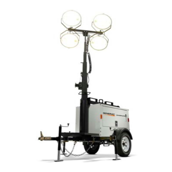
General Information Component Locations Figure 2-3. Component Locations Mast Rotation Knob Fuel Fill Central Lift Point Outriggers Engine Exhaust Engine Access Forklift Pockets Battery Radiator Access Control Box Owner’s Manual for MLT3060M-K Light Tower... -
Page 21: Control Panel
General Information Control Panel Figure 2-4. Control Panel Owner’s Manual for MLT3060M-K Light Tower... -
Page 22: Control Panel Features And Functions
General Information Control Panel Features and Functions (G) DC Breaker 10A circuit breaker for the engine electrical system. (A) Main Circuit Breaker (H) 120V GFCI Outlet 240V/30A breaker which disconnects power from the lights and control panel. 120V/20A GFCI outlet supplies power for accessories connected to the generator when the engine is running (B) Light Switches (4) and the main circuit breaker is ON (I). -
Page 23: Powerzone-Dla (If Equipped)
General Information PowerZone–DLA (If Equipped) engine will be shut down automatically and the LCD window will show the fault that caused the shutdown. To The PowerZone–DLA is an AUTO start controller that resume operation, the fault condition must be corrected. monitors the unit and indicates operational status and This controller also records a history of unit performance, fault conditions. -
Page 24: Operator Screens
General Information Operator Screens Figure 2-6. The operator screens display the most relevant and critical information an operator will need to properly configure and use the unit. From these six screens, the operator can access information necessary to operate the unit under normal conditions. 002355 Figure 2-8. - Page 25 General Information Scheduler Screen To select the required icon, press the ↑ button to cycle right and the ↓ button to cycle left until the Figure 2-10. The Scheduler screen enables the desired operator screen section is reached. operator to program specific times for the lights to turn ON and OFF.
- Page 26 General Information Maintenance Screen Figure 2-13. The Maintenance screen ( ) displays Table 2-1. Possible DTC Faults the maintenance alarms configured into the controller. The three alarms are for servicing the fuel filter, oil filter, Fault DTC Description and air filter. A fault not recognized by the controller Check Engine has been detected.
- Page 27 General Information About Screen Figure 2-15. The About ( ) screen contains information about the controller such as the controller’s date and time, the product and USB identification number, and the application and engine version. 003783 Figure 2-15. About Screen Owner’s Manual for MLT3060M-K Light Tower...
- Page 28 General Information This page intentionally left blank. Owner’s Manual for MLT3060M-K Light Tower...
-
Page 29: Section 3: Operation
Operation Section 3: Operation Light Tower Setup DETAIL C DETAIL D DETAIL G 003789 DETAIL H Figure 3-1. Set Up Outriggers and Jacks 4. A grounding stud (C) is located on the control box. For grounding requirements, follow the National DANGER Electrical Code (NEC), state, and local regulations. -
Page 30: Prestart Checklist
Operation Prestart Checklist Raising the Mast Before starting the unit, all items in the prestart checklist 1. Set up and level the unit. See Light Tower Setup. must be completed. This checklist applies to both manual WARNING and remote starting of the unit. Tipping hazard. -
Page 31: Starting The Unit
Operation 2. See Figure 3-2. Remove mast cradle locking pin 1. See Figure 3-3. Verify the main circuit breaker and from mast cradle (A). individual circuit breakers for each of the lights are OFF (O). 3. Check the mast cables for excessive wear or damage. -
Page 32: Preparing For Start-Up (With Powerzone Controller, If Equipped)
Operation 3. See Figure 3-5. As soon as it is glowing, turn the key to the right START position and hold it until the engine cranks and starts running. GLOW PLUG START 002354 Figure 3-7. Select AUTO or MANUAL Mode 003793 Figure 3-5. -
Page 33: Light Operation
Operation Light Operation (With 8. Check the generator for excessive noise or vibration and any leaking coolant, oil, or fuel before PowerZone Controller, If applying loads. Equipped) 9. Once the engine is running, allow it to reach normal operating temperature turning on the outlet Figure 3-8. -
Page 34: Wet Stacking
Operation Wet Stacking Shutting Down the Unit The unit is powered by a diesel engine. Diesel engines Check with personnel using power supplied by the unit are subject to “wet stacking” if lightly loaded. Wet and let them know the power is going to be turned off. stacking occurs when an engine is run at less than 30% Verify the power shutdown will not create any hazards by of its full load capacity, causing unburned fuel to... -
Page 35: Spark Arrester (If Equipped)
Operation NOTE: Use the lower radiator hose heater only in its NOTE: If the mast lock bar does not pull free, activate designated location. Improper use can damage the the lower winch slightly to relieve pressure on the mast engine. bar. -
Page 36: Tying The Unit Down
Operation Lifting the Unit 7. See Figure 3-10. Check the wheel lugs. Tighten or replace any lugs that are loose or missing. If a tire Follow these steps to prepare the unit for lifting: has been removed for axle service or replaced, 1. -
Page 37: Section 4: Maintenance
Maintenance Section 4: Maintenance Emissions Information Verify the circuit breakers are switched OFF (O). Disconnect the negative (–) terminal on the battery. For warranty information, please refer to the diesel Attach a “Do Not Start” sign to the control panel. engine manual supplied with this unit. -
Page 38: Basic Maintenance Schedule
Maintenance Basic Maintenance Schedule Verify the oil is correct for special operating conditions such as a change in season or climate. Refer to the original equipment manufacturer’s operating • DO NOT start the unit if the engine oil level is manual for a complete list of maintenance requirements. - Page 39 Maintenance Table 4-1. Basic Maintenance Guide - MLT3060M 1000 Item Daily Hours Hours Hours Hours Hours Required Check Oil Level Check Coolant Level Check Fuel Level Check Tire Pressure Inspect Wheel Bearings Check All Electrical Connections Inspect Radiator Fins For Debris;...
- Page 40 Maintenance Table 4-2. Basic Maintenance Guide - MLT3060K Item Daily Yearly Hours Hours Hours Hours Hours Check Oil Level Check Coolant Level Check Fuel Level Check Tire Pressure Inspect Wheel Bearings Check All Electrical Connections ...
-
Page 41: Resetting The Maintenance Alarms (If Equipped)
Maintenance Resetting the Maintenance Winch Use, Operation and Alarms (If Equipped) Maintenance The PowerZone–DLA will display a warning message Prior to Use when the unit is due for maintenance or service. The • maintenance or service interval is set at 750 hours of Inspect rope or cable and replace if damaged. -
Page 42: Jack Maintenance
Maintenance Jack Maintenance Before each use, check each jack foot for damage and remove any mud or debris. The jacks must be clean and in good operating condition to properly support the unit. Trailer Wheel Bearings The trailer axles are equipped with a Zerk grease fitting to allow lubrication of the wheel bearings without the need to disassemble the axle hub. -
Page 43: Section 5: Troubleshooting
Troubleshooting Section 5: Troubleshooting General Troubleshooting Some of the more common problems are listed in the table below. This information is intended to be a check or verification that simple causes can be located and fixed. It does not cover all types of problems. Refer to the OEM engine operator’s manual for additional troubleshooting information. -
Page 44: Troubleshooting The Lights
Troubleshooting Troubleshooting the Lights WARNING IMPORTANT NOTE: Only a qualified electrician should troubleshoot or repair electrical problems Burn hazard. Lamps become extremely hot occurring in this equipment. Contact Generac Mobile while in use. Allow 10–15 minutes for cooling Products Technical Service at 1-800-926-9768 for before handling or lowering mast. -
Page 45: Section 6: Wiring Diagrams
Wiring Diagrams Section 6: Wiring Diagrams Mast Junction Box Wiring and Light Connections 00175 Owner’s Manual for MLT3060M-K Light Tower... -
Page 46: Ac Wiring
Wiring Diagrams AC Wiring 90347_E_06.21.14 Owner’s Manual for MLT3060M-K Light Tower... -
Page 47: Dc Wiring-Mlt3060M
Wiring Diagrams DC Wiring—MLT3060M Owner’s Manual for MLT3060M-K Light Tower... -
Page 48: Dc Wiring-Mlt3060K
Wiring Diagrams DC Wiring—MLT3060K After serial number: 0900090 90339_E_01.30.14 Owner’s Manual for MLT3060M-K Light Tower... -
Page 49: Dc Wiring For Optional Equipment
Wiring Diagrams DC Wiring for Optional Equipment 90323_K_06.04.14 Owner’s Manual for MLT3060M-K Light Tower... -
Page 50: Trailer Wiring
Wiring Diagrams Trailer Wiring SPADE SPADE 90341_B_12.20.13 Owner’s Manual for MLT3060M-K Light Tower... - Page 51 Wiring Diagrams This page intentionally left blank. Owner’s Manual for MLT3060M-K Light Tower...
- Page 52 Wiring Diagrams This page intentionally left blank. Owner’s Manual for MLT3060M-K Light Tower...
- Page 53 Service Log Notes ______________________________________ OIL GRADE: ___________________________________ ______________________________________ COOLANT MIXTURE: ___________________________ ______________________________________ ______________________________________________ ______________________________________ ______________________________________________ ______________________________________ ______________________________________________ ______________________________________ ______________________________________________ ______________________________________ ______________________________________________ ______________________________________ ______________________________________________ ______________________________________ ______________________________________________ ______________________________________ ______________________________________________ ______________________________________ ______________________________________________ ______________________________________ Hours to Coolant Date Oil Level ______________________________________ Service Level ______________________________________ ______________________________________ ______________________________________ ______________________________________...
- Page 54 This page intentionally left blank. Owner’s Manual for MLT3060M-K Light Tower...
- Page 56 Part No. 10714 Rev. J 03/23/17 ©2017 Generac Mobile Products All rights reserved. Specifications are subject to change without notice. Generac Mobile Products No reproduction allowed in any form without prior written consent 215 Power Drive, Berlin, WI 54923 from Generac Mobile Products. GeneracMobileProducts.com │800-926-9768 │920-361-4442...
Need help?
Do you have a question about the Magnum MLT3060M and is the answer not in the manual?
Questions and answers