
Subscribe to Our Youtube Channel
Related Manuals for Generac Power Systems MAGNUM MLT5060M


Summary of Contents for Generac Power Systems MAGNUM MLT5060M
- Page 1 Owner’s Manual Light Tower MLT5060M • MLT5060K MLT5080M • MLT5080K • MLT5080KCAN www.discount-equipment.com SAVE THIS MANUAL FOR FUTURE REFERENCE...
- Page 2 Discount-Equipment.com is your online resource for commercial and industrial quality parts and equipment sales. Locations: Florida (West Palm Beach): 561-964-4949 Outside Florida TOLL FREE: 877-690-3101 Need parts? Check out our website at www.discount-equipment.com Can’t find what you need? Click on this link: http://www.discount-equipment.com/category/5443-parts/ and fill out the request form.
- Page 3 Use this page to record important information about your Light Tower Record the information found on your unit data label on this page. See unit serial number location (Unit Serial Unit Model Number Number Locations). The label plate is affixed to the inside partition, to the left of the control panel console.
-
Page 4: Table Of Contents
Table of Contents Section 1: Introduction and Safety Starting the Unit ..........19 Automatic Shutdown ........20 Introduction ............1 Read This Manual Thoroughly ........1 Light Operation ..........20 How to Obtain Service ..........1 Auxiliary Outlets ..........21 Safety Rules ............1 Wet Stacking ............ - Page 5 DC Wiring Diagram—Mitsubishi .......35 DC Wiring Diagram—Kubota ......36 DC Wiring Diagrams for Optional Equipment .37 Trailer Lights Wiring ..........38 Section 7:Service Log Owner’s Manual for MLT Light Tower...
-
Page 6: Section 1: Introduction And Safety
Introduction and Safety Section 1: Introduction and Safety Introduction Safety Rules Thank you for purchasing a Generac Mobile Products LLC The manufacturer cannot anticipate every possible product. This unit has been designed to provide high circumstance that might involve a hazard. The warnings in performance, efficient operation, and years of use when this manual, and on tags and decals affixed to the unit are, maintained properly. -
Page 7: General Hazards
Introduction and Safety General Hazards Explosion and Fire Hazards DANGER DANGER Asphyxiation. Running engines produce Explosion and Fire. Fuel and vapors are carbon monoxide, a colorless, odorless, extremely flammable and explosive. Add fuel poisonous gas. Carbon monoxide, if not in a well ventilated area. Keep fire and spark away. -
Page 8: Electrical Hazards
Introduction and Safety Electrical Hazards Battery Hazards DANGER DANGER Electrocution. In the event of electrical accident, Electrocution. Do not wear jewelry while immediately shut power OFF. Use non-conductive working on this equipment. Doing so will implements to free victim from live conductor. Apply result in death or serious injury. -
Page 9: Fuel Hazards
Introduction and Safety Fuel Hazards Operating Safety Positioning the Unit DANGER Explosion and fire.Fuel and vapors are extremely DANGER flammable and explosive. No leakage of fuel is High Voltage. Verify area above unit is clear permitted. Keep fire and spark away. Failure to do of overhead wires and obstructions. -
Page 10: Raising And Lowering The Mast
Introduction and Safety Service Safety Raising and Lowering the Mast This unit uses high voltage circuits capable of causing WARNING serious injury or death. Only a qualified and licensed Electrocution. Do not set up or operate electrician should troubleshoot or repair problems this unit if severe weather is expected. -
Page 11: Towing Safety
Introduction and Safety Towing Safety Reporting Trailer Safety Defects Towing a trailer requires care. Both the trailer and vehicle If you believe your trailer has a defect which could cause must be in good condition and securely fastened to each a crash or could cause injury or death, you should other to reduce the possibility of an accident. -
Page 12: Section 2: General Information
General Information Section 2: General Information Specifications DESCRIPTION UNITS MLT5060M MLT5060K Engine Make/Brand — MITSUBISHI KUBOTA Model — L3E-W461ML D1005-E3BG1-MGM-1 EPA Tier — Type — Diesel, liquid cooled, 4-stroke Horsepower - prime hp (kW) 10.5 (7.8) 11.7 (8.7) Horsepower - standby hp (kW) 12.2 (9.1) 13.1 (9.8) - Page 13 General Information DESCRIPTION UNITS MLT5080M MLT5080K, MLT5080KCAN Engine Make/Brand — MITSUBISHI KUBOTA Model — L3E-W461ML D1105-E3BG EPA Tier — Type — Diesel, liquid cooled, 4-stroke Horsepower - prime hp (kW) 10.5 (7.8) 13.5 (10.1) Horsepower - standby hp (kW) 12.2 (9.1) 15.4 (11.5) Operating Speed 1800...
-
Page 14: Unit Dimensions
General Information Unit Dimensions 004696 Figure 2-1. Unit Dimensions MLT5060M/K 170 in 72 in 30 ft 79 in 151 in MLT5080M/K (4.32 m) (1.83 m) (9.14 m) (2 m) (3.84 m) MLT5080KCAN Specifications are subject to change without notice. Owner’s Manual for MLT Light Tower... -
Page 15: Unit Serial Number Locations
General Information Unit Serial Number Locations Refer to the illustration to locate the unit ID tag and Vehicle Identification Number (VIN) tag on the unit. Important information, such as the unit serial number, model number, VIN and tire loading information are found on these tags. -
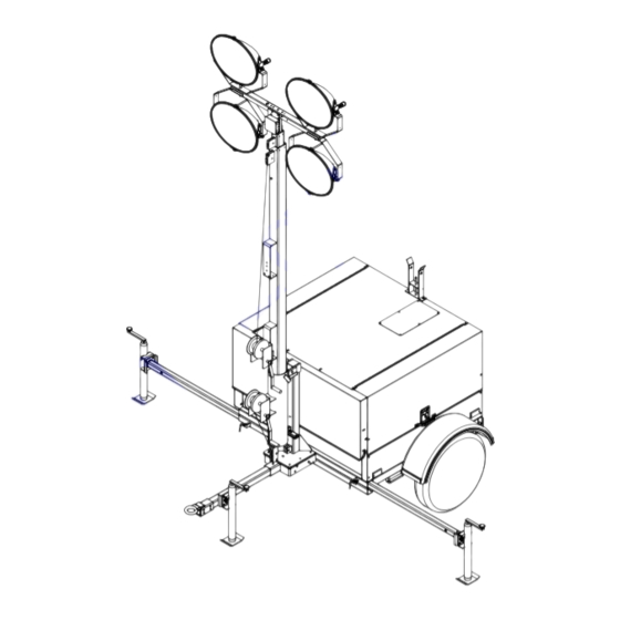
Page 16: Component Locations
General Information Component Locations LEFT SIDE RIGHT SIDE 004509 Figure 2-3. Component Locations Mast rotation knob Battery Fuel fill Central lifting point Control box Outriggers Engine exhaust Radiator box Engine access Lower Forklift pockets Upper forklift pockets — — Owner’s Manual for MLT Light Tower... -
Page 17: Control Panel - Mlt5060M, Mlt5060K
General Information Control Panel - MLT5060M, MLT5060K BALLAST INDICATOR LIGHTS MAIN BREAKER 240V TURN MAIN BREAKER MAST LIGHT SWITCHES 400W 400W 120V Flagger Station Switches BREAKER GLOW PLUG GLOW INDICATOR PLUG START 120V 240V BREAKER NEUTRAL BONDED TO FRAME 004548 Figure 2-4. -
Page 18: Control Panel Features And Functions
General Information Control Panel Features and Functions (G) DC Circuit Breaker (A) Main Circuit Breaker Circuit breaker (10A) for the engine electrical system. This 240V (30A) breaker will disconnect power to the lights and auxiliary outlets. It will also disable the starting (H) 240V Twist-Lock Outlet circuit if engine starting is attempted when the main This 240V (30A) outlet supplies power for accessories... -
Page 19: Control Panel - Mlt5080M, Mlt5080K, Mlt5080Kcan
General Information Control Panel - MLT5080M, MLT5080K, MLT5080KCAN BALLAST INDICATOR LIGHTS MAIN BREAKER 240V TURN MAIN BREAKER MAST LIGHT SWITCHES 120V 120V BREAKER BREAKER GLOW PLUG 240V START BREAKER 120V 120V 240V BREAKER NEUTRAL BONDED TO FRAME 004554 Figure 2-5. Control Panel Owner’s Manual for MLT Light Tower... -
Page 20: Control Panel Features And Functions
General Information Control Panel Features and Functions (G) DC Circuit Breaker (A) Main Circuit Breaker Circuit breaker (10A) for the engine electrical system. This 240V (30A) breaker will disconnect power to the lights and auxiliary outlets. It will also disable the starting (H) 120V GFCI Outlets circuit if engine starting is attempted when the main This unit is equipped with one 120V (20A) GFCI outlet to... -
Page 21: Section 3:Operation
Operation Section 3: Operation Light Tower Setup DETAIL C DETAIL D DETAIL G DETAIL H 004697 Figure 3-1. Set Up Outriggers and Jacks 2. See Figure 3-1. Place the unit on firm ground that is relatively flat (less than 5° slope), and then block DANGER the wheels to keep it from moving (A).This will make it easier to level the unit. -
Page 22: Prestart Checklist
Operation Raising the Mast place. Turn the jack handle clockwise to start leveling the trailer. 1. Set up and level the unit. See Light Tower Setup. 7. Rotate each jack handle clockwise to start leveling the trailer. Adjust all four jacks by rotating their DANGER handles clockwise until they are firmly in contact Electrocution. -
Page 23: Starting The Unit
Operation 3. Check the mast cables for excessive wear or 1. See Figure 3-3. Verify the main circuit breaker and damage. Verify the cables are properly centered in individual circuit breakers for each of the lights are each pulley (B). Check the electrical cord for OFF (O). -
Page 24: Automatic Shutdown
Operation NOTE: If oil pressure is not obtained within 15 seconds exceeds normal operating temperature. Return the main after the key is switched to the “RUN” position, the low oil circuit breaker to the OFF position to reset the unit after automatic shutdown will turn off the fuel supply, stopping the cause of shutdown has been determined. -
Page 25: Auxiliary Outlets
Operation Voltage Regulator Option Some units may be equipped with an electronic voltage WARNING regulator. The electronic voltage regulator controls the Burn hazard. Lamps become extremely hot output of the generator by regulating the current into the while in use. Allow 10–15 minutes for cooling exciter field. -
Page 26: Lowering The Mast
Operation Lowering the Mast 4. Insert the lights onto the light storage channel, located on the inside of each door. WARNING 5. Orient the lights so the lenses are facing the rubber seal on the inside of the door, as shown. Burn hazard. -
Page 27: Lifting The Unit
Operation 6. Verify the enclosure is properly latched and the 6. Use the upper (B) or lower forklift pockets (C) with mast cradle lock is in place. care. Approach the unit as perpendicular as possible to avoid any damage to the unit. Make 7. -
Page 28: Section 4:Maintenance
Maintenance Section 4: Maintenance Emissions Information Attach a “Do Not Start” sign to the control panel. This will notify everyone that the unit is being For warranty information, please refer to the diesel serviced and will reduce the chance of someone engine manual supplied with this unit. -
Page 29: Basic Maintenance Schedule
Maintenance Basic Maintenance Schedule • Check the coolant level daily by inspecting the level in coolant overflow jug located near the Refer to the original equipment manufacturer’s operating radiator. Refer to the engine operator’s manual for manual for a complete list of maintenance requirements. coolant recommendations and proper mixture. - Page 30 Maintenance Table 4-1. Basic Maintenance Guide (Mitsubishi) 1000 Item Daily Hours Hours Hours Hours Hours Required Check Oil Level Check Coolant Level Check Fuel Level Check Tire Pressure Check All Electrical Connections Inspect Radiator Fins For Debris, Clean As Required ...
-
Page 31: Winch Use, Operation And Maintenance
Maintenance Table 4-2. Basic Maintenance Guide (Kubota) Item Daily Hours Hours Hours Hours Hours Year Replace Oil Filter Cartridge * Replace Fuel Filter Cartridge Clean Water Separator Lubricate Leveling Jacks Remove Sediment In Fuel Tank Replace Fan Belt ... -
Page 32: Trailer Wheel Bearings
Maintenance • Heater is designed for all-night operation; how- ever, 2-5 hours of heating just prior to starting is usually sufficient for proper engine starting. • When heater is in operation, unit must be parked in a level position to maintain the proper orientation of the heater. -
Page 33: Section 5:Troubleshooting
Troubleshooting Section 5: Troubleshooting General Troubleshooting Some of the more common problems are listed in the table below. This information is intended to be a check or verification that simple causes can be located and fixed. It does not cover all types of problems. Refer to the OEM engine operator’s manual for additional troubleshooting information. -
Page 34: Troubleshooting The Lights
Troubleshooting Troubleshooting the Lights IMPORTANT NOTE: Only a qualified electrician WARNING should troubleshoot or repair electrical problems occurring in this equipment. Burn hazard. Lamps become extremely hot while in use. Allow 10–15 minutes for cooling before handling or lowering mast. Touching a hot lens or fixture can cause severe burns. -
Page 35: Section 6:Wiring Diagrams
Wiring Diagrams Section 6: Wiring Diagrams Mast Junction Box Wiring and Light Connections 00768 Owner’s Manual for MLT Light Tower... -
Page 36: Ac Wiring Diagram
Wiring Diagrams AC Wiring Diagram 90347_E_06.21.14 Owner’s Manual for MLT Light Tower... -
Page 37: Dc Wiring Diagram—Mitsubishi
Wiring Diagrams DC Wiring Diagram—Mitsubishi Owner’s Manual for MLT Light Tower... -
Page 38: Dc Wiring Diagram—Kubota
Wiring Diagrams DC Wiring Diagram—Kubota After Serial Number 0900090 90339_E_01.30.14 Owner’s Manual for MLT Light Tower... -
Page 39: Dc Wiring Diagrams For Optional Equipment
Wiring Diagrams DC Wiring Diagrams for Optional Equipment 90323_K_06.04.14 Owner’s Manual for MLT Light Tower... -
Page 40: Trailer Lights Wiring
Wiring Diagrams Trailer Lights Wiring SPADE SPADE 90341_B_12.20.13 Owner’s Manual for MLT Light Tower... - Page 41 Discount-Equipment.com is your online resource for commercial and industrial quality parts and equipment sales. Locations: Florida (West Palm Beach): 561-964-4949 Outside Florida TOLL FREE: 877-690-3101 Need parts? Check out our website at www.discount-equipment.com Can’t find what you need? Click on this link: http://www.discount-equipment.com/category/5443-parts/ and fill out the request form.
- Page 42 www.discount-equipment.com Part No. 10413 Rev. L 3/9/17 ©2017 Generac Mobile Products All rights reserved. Specifications are subject to change without notice. No reproduction allowed in any form without prior written consent from Generac Mobile Products.
Need help?
Do you have a question about the MAGNUM MLT5060M and is the answer not in the manual?
Questions and answers