Table of Contents
Advertisement
Instruction Leaflet IB2C12063H03
Instructions for Installation, Operation
and Maintenance of Magnum SB
Insulated Case Low Voltage Power
Circuit Breakers
WARNING
DO NOT ATTEMPT TO INSTALL OR PERFORM MAINTENANCE
ON EQUIPMENT WHILE IT IS ENERGIZED. DEATH OR SEVERE
PERSONAL INJURY CAN RESULT FROM CONTACT WITH
ENERGIZED EQUIPMENT. ALWAYS VERIFY THAT NO VOLTAGE
IS PRESENT BEFORE PROCEEDING. ALWAYS FOLLOW
SAFETY PROCEDURES. EATON IS NOT LIABLE FOR THE
MISAPPLICATION OR MISINSTALLATION OF ITS PRODUCTS.
WARNING
OBSERVE ALL RECOMMENDATIONS, NOTES, CAUTIONS, AND
WARNINGS RELATING TO THE SAFETY OF PERSONNEL AND
EQUIPMENT. OBSERVE AND COMPLY WITH ALL GENERAL
AND LOCAL HEALTH AND SAFETY LAWS, CODES, AND
PROCEDURES.
CAUTION
TESTING A CIRCUIT BREAKER WHILE IN-SERVICE AND
CARRYING LOAD CURRENT IS NOT RECOMMENDED FOR
POWER AND MEDIUM VOLTAGE CIRCUIT BREAKERS. TESTING
THAT RESULTS IN THE TRIPPING OF THE CIRCUIT BREAKER
SHOULD BE DONE ONLY WITH THE CIRCUIT BREAKER IN A
DEENERGIZED SYSTEM OR IN THE TEST OR DISCONNECTED
CELL POSITIONS OR WHILE IT IS ON A TEST BENCH.
PERFORMING TESTS WITHOUT THE EATON-APPROVED TEST
KIT MAY DAMAGE THE TRIP UNIT.
effective March 2012
Advertisement
Table of Contents

Related Manuals for Eaton SBN-508


Summary of Contents for Eaton SBN-508
- Page 1 PERSONAL INJURY CAN RESULT FROM CONTACT WITH ENERGIZED EQUIPMENT. ALWAYS VERIFY THAT NO VOLTAGE IS PRESENT BEFORE PROCEEDING. ALWAYS FOLLOW SAFETY PROCEDURES. EATON IS NOT LIABLE FOR THE MISAPPLICATION OR MISINSTALLATION OF ITS PRODUCTS. WARNING OBSERVE ALL RECOMMENDATIONS, NOTES, CAUTIONS, AND WARNINGS RELATING TO THE SAFETY OF PERSONNEL AND EQUIPMENT.
-
Page 2: Table Of Contents
Yoke Attached . . . . . . . . . . . . . . . . . . . . . . . . . . . . . . . . . . 10 EATON CORPORATION www.eaton.com... - Page 3 Breaker Closed) . . . . . . . . . . . . . . . . . . . . . . . . . . . . . . . . . 24 EATON CORPORATION www.eaton.com...
- Page 4 Arc Chute Removed . . . . . . . . . . . . . . . . . . . . . . . . . . . . . 61 EATON CORPORATION www.eaton.com...
-
Page 5: Section 1: Introduction
. This information is also available from strength structural properties, excellent dielectric characteristics the Eaton website at www .EatonElectrical .com . and arc tracking resistance . For application information, consult Eaton or see applicable... -
Page 6: Safety Features
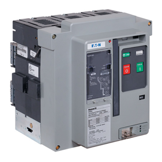
Figure 1. Family of Magnum SB Low Voltage Power Fixed and Drawout Circuit Breakers (800-5000 Amperes) Safety Features Magnum SB circuit breakers and associated drawout equipment are manufactured with built-in interlocks and safety related features . They are provided to reduce hazards to operating personnel and provide proper operating sequences . EATON CORPORATION www.eaton.com... -
Page 7: Safety Practices
5000 SBS-850 18 X In must be followed: 5000 SBS-C50 18 X In 5000 SBS-E50 50kA j In is defined by the current sensor and rating plug combination k Short Time Rating at 635v is 65kA EATON CORPORATION www.eaton.com... -
Page 8: Qualified Personnel
Product (application) Guide . Specific reference documents associated • 17 mm socket with Magnum SB circuit breakers are listed in a separate • Secondary wiring removal tool document entitled Engineering Data TD01301004E . EATON CORPORATION www.eaton.com... -
Page 9: Unpacking Circuit Breaker
. Record any observed damage for reporting to the transportation carrier and Eaton, once the inspection is completed . All reports and claims should be as specific as possible and include the order number and other applicable nameplate information . -
Page 10: Lifting Circuit Breaker
(Figure 5) . Every effort should be made during lifting to minimize circuit breaker swing and tilt . EATON CORPORATION www.eaton.com... -
Page 11: Circuit Breaker Inspection
RAILS, IT COULD FALL FROM THE RAILS CAUSING EQUIPMENT Molded Rail DAMAGE AND/OR BODILY INJURY. Supports Extension Rail Cutout Figure 7. One Side of Drawout Circuit Breaker Properly Seated on Figure 6. Rear View Showing Current Sensor Rating Through Extension Rail Viewing Window EATON CORPORATION www.eaton.com... -
Page 12: Figure 8. Cassette Rejection Interlock Pin Positioning/Installation For Standard And Double-Wide Frames
Figure 8. Cassette Rejection Interlock Pin Positioning/Installation for Standard and Double-wide Frames From Table 4, make certain the two bolts are in the correct locations . Figure 9. Cassette Rejection Interlock Bracket Location/ Installation for Narrow Frames EATON CORPORATION www.eaton.com... -
Page 13: Figure 10. Remove Position
Figure 11. Disconnect Position Secondary Connection Made Rear of Compartment Compartment Front Door Circuit Breaker Primary Side View Connections Not Made Breaker and Trip Unit Testing Primary Connection Not Made Secondary and Ground Connections Made Figure 12. Test Position EATON CORPORATION www.eaton.com... -
Page 14: Circuit Breaker Positioning
CONNECT, positions are reached by means of the levering indicators (Red = Connect, Yellow = Test, Green = Disconnect) mechanism . (Figures 15 and 20) . To remove the circuit breaker from its compartment, follow the procedure just described using a counterclockwise ratcheting motion . EATON CORPORATION www.eaton.com... -
Page 15: Fixed Circuit Breaker
. Both secondary connection devices are mounted at the top front of the circuit breaker . EATON CORPORATION www.eaton.com... -
Page 16: Section 3: Circuit Breaker Description And Operation
1 . Baffled Arc Chute Cover 2 . Secondary Disconnects (Contacts) 3 . Faceplate (Front Cover) 4 . Drawout Rail Supports 5 . Integral Lifting Handle Figure 17. Typical Drawout Circuit Breaker Features (Front and Rear Views) EATON CORPORATION www.eaton.com... -
Page 17: Figure 18 . Typical Sbs/Sbse Fixed Circuit Breaker Features
2 . Secondary Contact Connector 3 . Faceplate (Front Cover) 4 . Integral Lifting Handle 5 . Fixed Horizontal Primary Terminal Figure 18. Typical SBS/SBSE Fixed Circuit Breaker Features (Front and Rear Views) (SBSE shown without required arc hood) EATON CORPORATION www.eaton.com... -
Page 18: Figure 19 . Typical Double-Wide Sbs/Sbse Standard Frame Fixed Circuit Breaker Features (Front And Rear Views)
8 . Circuit Breaker Nameplate 3 . Faceplate (Front Cover) 9 . Phase Identification Labels 4 . Integral Lifting Handle Figure 19. Typical Double-wide SBS/SBSE Standard Frame Fixed Circuit Breaker Features (Front and Rear Views) (SBSE shown without required arc hood) EATON CORPORATION www.eaton.com... -
Page 19: Figure 20 . Typical Magnum Sb Drawout Circuit
5 . Contact Status (Open-Close) 11 . Padlockable Levering Device Screws (Mounting Screws will Access Door for Drawout Breaker 6 . Spring Status (Charged-Discharged) Accept Customer Supplied Lead Security Meter Seals Figure 20. Typical Magnum SB Drawout Circuit Breaker Front Cover EATON CORPORATION www.eaton.com... -
Page 20: Basic Circuit Breaker Assembly
. (Front Cover) (Case) Moving Main Contact Conductive Pad (Heel) Dual Flexible Connections Figure 22. Features of Magnum Moving Conductor Assembly Figure 21. Typical Magnum Construction (Right Side View) EATON CORPORATION www.eaton.com... -
Page 21: Primary Stationary Contacts
. The integral arc runner serves a dual purpose: • Fixed arcing contact • Part of the arc chute Figure 26. Partial Cross-Sectional View (Shown in Closed Position) EATON CORPORATION www.eaton.com... -
Page 22: Operating Mechanism
4 . Electric Charging Motor 5 . Manual Charge Handle 6 . Operations Counter (optional) 7 . Padlockable Levering Device Access Door 8 . Breaker Position Indicator Figure 27. Typical Electrically Operated Drawout Circuit Breaker with Front Cover Removed EATON CORPORATION www.eaton.com... -
Page 23: Electrical Operation
. For electrical closing, a Latch Check Switch (LCS) option is available (Refer to page 49 for details) which will block the application of the electrical close command until the breaker is ready to close . EATON CORPORATION www.eaton.com... -
Page 24: Electronic Tripping System
Arcing Contact Figure 31. Magnum Arc Plate Assembly Integral Arc Runner Figure 30. Cross Section of Conductor and Arc Control System Figure 32. Integral Arc Runner Viewed From Top of Arc Chamber (Arc Chute Removed, Circuit Breaker Closed) EATON CORPORATION www.eaton.com... -
Page 25: Effective March
Three-line, (eight characters per line) LED display. curves to coordinate with a load or system, refer to the trip unit l Phase, neutral, ground, and high load current only. instruction book . m Available control voltages are 24/48Vdc, 125Vdc, 120Vac and 240Vac EATON CORPORATION www.eaton.com... -
Page 26: Rating Plug
. They are wired to the trip unit through the secondary contacts of the circuit breaker . Refer to Table 6 for a tabulation of the available current sensor ratings . Figure 35. Hand Held Tester EATON CORPORATION www.eaton.com... -
Page 27: Trip Actuator
(Figure 34) . It operates by releasing and trip value is maintained . popping out any time the circuit breaker trips due to to an overcurrent condition . Note that the mechanical trip indicator EATON CORPORATION www.eaton.com... -
Page 28: Voltage Taps
PowerNet Communications Network A BUS (Future Use) Auxiliary Contacts NEUTRAL Neutral Sensor Input GF SGND Source Ground Input ZONE Zone Interlocking Shunt Trip Spring Release MOTOR Charging Motor Latch Check Switch Figure 38. Top View Secondary Connectors EATON CORPORATION www.eaton.com... -
Page 29: Connection Diagrams
. Connection Diagrams Figure 41. AMP Secondary Wiring Removal Tool The connection diagrams for all Magnum SB circuit breakers using Digitrip RMS trip units are shown in Figures 42 through 59 . EATON CORPORATION www.eaton.com... -
Page 30: Figure 42 . Connection Diagram For Narrow And Standard
Instructional Leaflet Instructions for Installation, Operation and IB2C12063H03 Maintenance of Magnum SB Insulated Case Effective March 2012 Low Voltage Power Circuit Breakers Figure 42. Connection Diagram for Narrow and Standard Frame with Digitrip 520 and 520M EATON CORPORATION www.eaton.com... -
Page 31: Figure 43 . Connection Diagram For Narrow And Standard
Instructional Leaflet Instructions for Installation, Operation and IB2C12063H03 Maintenance of Magnum SB Insulated Case Effective March 2012 Low Voltage Power Circuit Breakers Figure 43. Connection Diagram for Narrow and Standard Frame with Digitrip 520MC EATON CORPORATION www.eaton.com... -
Page 32: Figure 44 . Connection Diagram For Narrow And Standard
Instructional Leaflet Instructions for Installation, Operation and IB2C12063H03 Maintenance of Magnum SB Insulated Case Effective March 2012 Low Voltage Power Circuit Breakers Figure 44. Connection Diagram for Narrow and Standard Frame with Digitrip 1150 EATON CORPORATION www.eaton.com... -
Page 33: Figure 45 . Connection Diagram For Standard Sbse Frame
Instructional Leaflet Instructions for Installation, Operation and IB2C12063H03 Maintenance of Magnum SB Insulated Case Effective March 2012 Low Voltage Power Circuit Breakers Figure 45. Connection Diagram for Standard SBSE Frame with Digitrip 520 and 520M EATON CORPORATION www.eaton.com... -
Page 34: Figure 46 . Connection Diagram For Standard Sbse Frame
Instructional Leaflet Instructions for Installation, Operation and IB2C12063H03 Maintenance of Magnum SB Insulated Case Effective March 2012 Low Voltage Power Circuit Breakers Figure 46. Connection Diagram for Standard SBSE Frame with Digitrip 520MC EATON CORPORATION www.eaton.com... -
Page 35: Figure 47 . Connection Diagram For Standard Sbse Frame
Instructional Leaflet Instructions for Installation, Operation and IB2C12063H03 Maintenance of Magnum SB Insulated Case Effective March 2012 Low Voltage Power Circuit Breakers Figure 47. Connection Diagram for Standard SBSE Frame with Digitrip 1150 EATON CORPORATION www.eaton.com... -
Page 36: Figure 48 . Connection Diagram For Double-Wide Frame (Except Sbse) With Digitrip 520 And 520M With Abcabc
Instructions for Installation, Operation and IB2C12063H03 Maintenance of Magnum SB Insulated Case Effective March 2012 Low Voltage Power Circuit Breakers Figure 48. Connection Diagram for Double-wide Frame (except SBSE) with Digitrip 520 and 520M with ABCABC Configuration EATON CORPORATION www.eaton.com... -
Page 37: Figure 49 . Connection Diagram For Double-Wide Frame
Instructional Leaflet Instructions for Installation, Operation and IB2C12063H03 Maintenance of Magnum SB Insulated Case Effective March 2012 Low Voltage Power Circuit Breakers Figure 49. Connection Diagram for Double-wide Frame (except SBSE) with Digitrip 520MC with ABCABC Configuration EATON CORPORATION www.eaton.com... -
Page 38: Figure 50. Connection Diagram For Double-Wide Frame (Except Sbse) With Digitrip 1150 With Abcabc Configuration
Instructional Leaflet Instructions for Installation, Operation and IB2C12063H03 Maintenance of Magnum SB Insulated Case Effective March 2012 Low Voltage Power Circuit Breakers Figure 50. Connection Diagram for Double-wide Frame (except SBSE) with Digitrip 1150 with ABCABC Configuration EATON CORPORATION www.eaton.com... -
Page 39: Figure 51 . Connection Diagram For Double-Wide Frame (Except Sbse) With Digitrip 520 And 520M With Aabbcc
Instructions for Installation, Operation and IB2C12063H03 Maintenance of Magnum SB Insulated Case Effective March 2012 Low Voltage Power Circuit Breakers Figure 51. Connection Diagram for Double-wide Frame (except SBSE) with Digitrip 520 and 520M with AABBCC Configuration EATON CORPORATION www.eaton.com... -
Page 40: Figure 52 . Connection Diagram For Double-Wide Frame
Instructional Leaflet Instructions for Installation, Operation and IB2C12063H03 Maintenance of Magnum SB Insulated Case Effective March 2012 Low Voltage Power Circuit Breakers Figure 52. Connection Diagram for Double-wide Frame (except SBSE) with Digitrip 520MC with AABBCC Configuration EATON CORPORATION www.eaton.com... -
Page 41: Figure 53. Connection Diagram For Double-Wide Frame (Except Sbse) With Digitrip 1150 With Aabbcc Configuration
Instructional Leaflet Instructions for Installation, Operation and IB2C12063H03 Maintenance of Magnum SB Insulated Case Effective March 2012 Low Voltage Power Circuit Breakers Figure 53. Connection Diagram for Double-wide Frame (except SBSE) with Digitrip 1150 with AABBCC Configuration EATON CORPORATION www.eaton.com... -
Page 42: Figure 54. Connection Diagram For Sbse Double-Wide Frame With Digitrip 520 And 520M With Abcabc Configuration
Instructional Leaflet Instructions for Installation, Operation and IB2C12063H03 Maintenance of Magnum SB Insulated Case Effective March 2012 Low Voltage Power Circuit Breakers Figure 54. Connection Diagram for SBSE Double-wide Frame with Digitrip 520 and 520M with ABCABC Configuration EATON CORPORATION www.eaton.com... -
Page 43: Figure 55. Connection Diagram For Sbse Double-Wide Frame With Digitrip 520Mc With Abcabc Configuration
Instructional Leaflet Instructions for Installation, Operation and IB2C12063H03 Maintenance of Magnum SB Insulated Case Effective March 2012 Low Voltage Power Circuit Breakers Figure 55. Connection Diagram for SBSE Double-wide Frame with Digitrip 520MC with ABCABC Configuration EATON CORPORATION www.eaton.com... -
Page 44: Figure 56 . Connection Diagram For Sbse Double-Wide Frame
Instructional Leaflet Instructions for Installation, Operation and IB2C12063H03 Maintenance of Magnum SB Insulated Case Effective March 2012 Low Voltage Power Circuit Breakers Figure 56. Connection Diagram for SBSE Double-wide Frame with Digitrip 1150 with ABCABC Configuration EATON CORPORATION www.eaton.com... -
Page 45: Figure 57. Connection Diagram For Sbse Double-Wide Frame With Digitrip 520 And 520M With Aabbcc Configuration
Instructional Leaflet Instructions for Installation, Operation and IB2C12063H03 Maintenance of Magnum SB Insulated Case Effective March 2012 Low Voltage Power Circuit Breakers Figure 57. Connection Diagram for SBSE Double-wide Frame with Digitrip 520 and 520M with AABBCC Configuration EATON CORPORATION www.eaton.com... -
Page 46: Figure 58. Connection Diagram For Sbse Double-Wide Frame With Digitrip 520Mc With Aabbcc Configuration
Instructional Leaflet Instructions for Installation, Operation and IB2C12063H03 Maintenance of Magnum SB Insulated Case Effective March 2012 Low Voltage Power Circuit Breakers Figure 58. Connection Diagram for SBSE Double-wide Frame with Digitrip 520MC with AABBCC Configuration EATON CORPORATION www.eaton.com... -
Page 47: Figure 59 . Connection Diagram For Sbse Double-Wide Frame
Instructional Leaflet Instructions for Installation, Operation and IB2C12063H03 Maintenance of Magnum SB Insulated Case Effective March 2012 Low Voltage Power Circuit Breakers Figure 59. Connection Diagram for SBSE Double-wide Frame with Digitrip 1150 with AABBCC Configuration EATON CORPORATION www.eaton.com... -
Page 48: Accessory Devices
110-125 Vdc 77-138 Vdc 450 W 220-250 Vdc 154-275 Vdc 450 W 110-127 Vac 77-140 Vac 450 VA 208-240 Vac 146-264 Vac 450 VA j Required for less than 35 ms Figure 62. Shunt Trip Switch Installed EATON CORPORATION www.eaton.com... -
Page 49: Figure 63 . Spring Release With Optional Latch Check Switch . 49 Figure 64 . Undervoltage Release Device
450 W 220-250 Vdc 154-275 Vdc 450 W 110-127 Vac 77-140 Vac 450 VA 208-240 Vac 146-264 Vac 450 VA Figure 65. Shunt Trip, Spring Release and Undervoltage Release Installed j Required for less than 200 ms EATON CORPORATION www.eaton.com... -
Page 50: Internal Electrical Accessories
380-415 Vac 323-457 Vac 114-249 Vac 480 VA/10 VA 480 Vac 408-528 Vac 144-288 Vac 400 VA/10 VA 600 Vac 510-660 Vac 180-360 Vac 400 VA/10 VA j Required for 200 ms k Required for 400 ms EATON CORPORATION www.eaton.com... -
Page 51: Figure 68. Motor Operator Kit
600% of Running Operations 110-127 Vac 94-140 600% of Running Counter 208-240 Vac 177-264 600% of Running j AC voltages are 50/60Hz “OFF” Key Lock Figure 70. Cover Mounted Key Lock and Operations Counter Figure 68. Motor Operator Kit EATON CORPORATION www.eaton.com... -
Page 52: Mechanical Accessories
Off Key Lock Up to three lock cylinders can be installed on one cassette . Eaton supplies the lock provisions only . The customer is The “off” key lock secures the circuit breaker in the “OFF” responsible for the locks, which can be Kirk, Castell, Ronis or position . -
Page 53: Figure 73. Typical Safety Shutters In Closed Position
(Figure 75 and 76) . Refer to Table 9 for cell switch contact information . The cell switch changes status between the TEST and CONNECT positions . Figure 77. Door Escutcheon and Gasket EATON CORPORATION www.eaton.com... -
Page 54: Figure 78. Ip54 Waterproof Cover
2-way and 3-way versions . An illustration Figure 79. Cassette-Mounted 2-Way Cable Interlock of a 2-way cable interlock mounted on two drawout circuit breakers is shown in Figure 79 . EATON CORPORATION www.eaton.com... -
Page 55: Section 4: Drawout Circuit Breaker And Cassette
(Figures 86) . Mounting locations for cell (TOC) switches, safety shutters, mechanical interlocks and key interlocks are provided on the cassette . Figure 80. Drawout Circuit Breaker in Cassette Figure 81. Drawout Circuit Breaker with Automatic Primary Disconnects EATON CORPORATION www.eaton.com... -
Page 56: Figure 82. Typical Drawout Cassette Features
6 . Optional Cell (TOC) Switch Mounting 2 . Extension Rail Cutout 7 . Optional Key Interlock Mounting Location 3 . Secondary Plug-in Connectors 8 . Grounding Bar 4 . Secondary Terminal Blocks Figure 82. Typical Drawout Cassette Features EATON CORPORATION www.eaton.com... -
Page 57: Drawout Circuit Breaker Dimensions
Engineering Data TD01301004E . Figure 85. Typical Standard Cassette (Vertical Terminals) Figure 83. Typical Narrow Frame Cassette (Horizontal Terminals) Figure 84. Typical Basic Cassette (Without Stabs) Figure 86. Typical Universal Cassette, 4-Pole (Flat Terminal Pads) EATON CORPORATION www.eaton.com... -
Page 58: Section 5: Fixed Circuit Breaker
The standard fixed circuit breaker is supplied with horizontally mounted primary connections (Figure 87) . Optional vertical primary adaptors are available for different bus configurations . Refer to Engineering Data TD01301004E for fixed circuit breaker dimensions, vertical adaptor dimensions and vertical adaptor assembly details . EATON CORPORATION www.eaton.com... -
Page 59: Section 6: Inspection And Maintenance
It is recommended that maintenance record sheets be com- damage, the inspection and maintenance interval should be pleted for the equipment . Careful and accurate documentation decreased . of all maintenance activities provides a valuable historical refer- ence on equipment condition over time . EATON CORPORATION www.eaton.com... -
Page 60: What To Inspect
POSITION AND THE MECHANISM SPRINGS DISCHARGED. During the levering out and levering in of the circuit breaker, be Eaton Cutler-Hammer recommends that the following func- aware for any signs that would indicate that this process is not tional tests be performed on Magnum circuit breakers as part working properly . -
Page 61: Manual Operation Functional Test
. Charge the breaker mechanism springs either using the charging handle or the motor operator . Figure 89. Top Rear View of Circuit Breaker with One Arc Chute Removed EATON CORPORATION www.eaton.com... -
Page 62: Primary Contact Inspection
Contact Wear Inspection) WHEN MAKING A CONTACT WEAR INSPECTION, ALWAYS MAKE THE INSPECTION BY LOOKING STRAIGHT DOWN INTO THE ARC CHAMBER FOR THE PROPER PERSPECTIVE. VIEWING THE CONTACT WEAR AREA FROM AN ANGLE COULD DISTORT THE VIEW. EATON CORPORATION www.eaton.com... -
Page 63: Breaker Frame Inspection
. Screws or bolts should be tightened to levels outlined in Table 14 . Loose screws inserted into plastic parts will require thread-lock- ing compound (such as Loctite 242) . All nicked wiring should be replaced . EATON CORPORATION www.eaton.com... -
Page 64: Breaker Mechanism Inspection
11-51 44th Road, Long Island City, New York 11101 Phone (718) 729-1000 Figure 95. Magnum DS Lubrication Fax (718) 729-2690 www.magnalube.com MolykoteT Eaton Standards #53701QB Color Black Manufactured by Dow Corning Corporation Midland, Michigan 48686-0994 (989) 636-1000 www.dowcorning.com/content/molykote/ EATON CORPORATION www.eaton.com... -
Page 65: Figure 96. Magnum Ds Lubrication
Swing Arm Swing Arm Path Lev-in Door Indexer Lev-in Door Interlock Figure 98. Magnum DS Lubrication Figure 96. Magnum DS Lubrication (Not applicable to Fixed- Mount Breakers) Figure 99. Magnum DS Lubrication Figure 97. Magnum DS Lubrication EATON CORPORATION www.eaton.com... -
Page 66: Circuit Breaker Modifications And Changes
The tasks described here do not, under ordinary circumstances, require any assistance beyond the appropriate instructional material . If further assistance is required, however, contact your Eaton representative . Rating Plug Replacement If a rating plug is not installed in the trip unit, the trip ote: unit will trip when energized . -
Page 67: Current Sensor Replacement
. Remove the vertical adaptors next from the circuit breaker terminals by removing the two or three 10 mm bolts holding them in place (Figure 104) . EATON CORPORATION www.eaton.com... -
Page 68: Section 7: Troubleshooting
Protective boots covering side plate stationary disconnects Remove boots Shutter jammed or locked Clear problem EATON CORPORATION www.eaton.com... -
Page 69: Section 8: Renewal Parts
. The Renewal Parts Documentation indicates which parts are available and in what form . For additional information, visit the Eaton website at www .EatonElectrical . com . EATON CORPORATION www.eaton.com... - Page 70 Disclaimer of warranties and limitation of liability The information, recommendations, descriptions, and safety In no event will Eaton be responsible to the purchaser or user in notations in this document are based on Eaton Corporation’s contract, in tort (including negligence), strict liability, or otherwise (“Eaton”) experience and judgment, and may not cover all...
Need help?
Do you have a question about the SBN-508 and is the answer not in the manual?
Questions and answers