Table of Contents
Advertisement
Quick Links
GENERAL
These direct-coupled damper actuators provide modulating
control for:
•
air dampers,
•
VAV units,
•
air handling units,
•
ventilation flaps,
•
louvers, and
•
reliable control for air damper applications with up to
2
4.6 m
/ 50 sq.ft. (20 Nm / 177 lb-in) or 7.8 m
(34 Nm / 300 lb-in) (seal-less dampers; air friction-
dependent).
FEATURES
•
New self-centering shaft adapter
•
Access cover to facilitate connectivity
•
Declutch for manual adjustment
•
Mechanical end limits
•
Field-installable auxiliary switches
•
Rotation direction selectable by switch
•
Mountable in any orientation (no IP54 if upside down)
•
Mechanical position indicator
® U.S. Registered Trademark
Copyright © 2007 Honeywell Inc. • All rights reserved
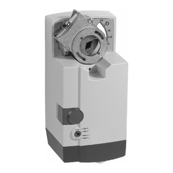
NON-SPRING RETURN DAMPER ACTUATOR
20/34 Nm (177/300 lb-in) FOR MODULATING CONTROL
2
/ 85 sq. ft.
N20010, N34010
SPECIFICATIONS
Supply voltage
Nominal voltage
All values stated hereinafter apply to operation under
nominal voltage conditions.
Power consumption
N20010
N34010
Ambient limits
Ambient operating limits
Ambient storage limits
Relative humidity
Safety
Protection standard
Protection class
Overvoltage category
Lifetime
Full strokes
Repositions
Mounting
Round damper shaft
Square damper shaft
Shaft length
Control signal
Input impedance
Feedback signal
Limits
End switches (when included)
Rating
Triggering points
Torque rating
N20010
N34010
Runtime
Rotation stroke
Weight (without cables)
Noise rating
Software
PRODUCT DATA
24 Vac ±20%, 50/60 Hz;
24 Vdc -10...+20%
24 Vac, 50/60 Hz; 24 Vdc
6 VA / 6 W
8 VA / 6 W
-20...+60 °C (-5...+140 °F)
-40...+80 °C (-40...+175 °F)
5...95%, non-condensing
IP54
II as per EN 60730-1
II
60000
1.5 million
10...27 mm (3/8...1-1/16")
10...18 mm (3/8...11/16");
45° steps
min. 22 mm (7/8")
0(2)...10 Vdc
0(4)...20 mA
100 kΩ [0...10 V]
500 Ωm [0...20 mA]
± 1 mA at 0...10 V
5 A (resistive) / 3 A (inductive)
5° / 85°
20 Nm (177 lb-in)
34 Nm (300 lb-in)
95 sec (60 Hz) / 110 sec (50 Hz)
95° ± 3°
see "Dimensions" on page 8
1.35 kg (3 lbs.)
45 dB(A) max. at 1 m
Class A as per EN 60730-1
EN0B-0341GE51 R0307
Advertisement
Table of Contents

Related Manuals for Honeywell N20010


Summary of Contents for Honeywell N20010
- Page 1 Mountable in any orientation (no IP54 if upside down) Noise rating 45 dB(A) max. at 1 m • Mechanical position indicator Software Class A as per EN 60730-1 ® U.S. Registered Trademark EN0B-0341GE51 R0307 Copyright © 2007 Honeywell Inc. • All rights reserved...
- Page 2 SmartAct N20010, N34010 MODELS order number supply voltage end switches control signal feedback torque N20010 24 Vac 0...10 Vdc / 0...20 mA 0...10 Vdc 20 Nm (177 lb-in) N20010-SW2 24 Vac 0...10 Vdc / 0...20 mA 0...10 Vdc 20 Nm (177 lb-in)
- Page 3 SmartAct N20010, N34010 Rotation Direction Switch Autoadapt Dip Switch for Normal Operation In its default shipping position, the autoadapt dip switch for normal operation is set to ON as shown in Fig. 4. If it is set to OFF, no autoadapting is performed, and the control signal map remains constant.
- Page 4 Fig. 8. Correct / incorrect tightening of end limits Internal End Switches NOTE: Only those actuators for which the option "-SW2" has been specified when ordering (e.g.: "N20010- SW2") feature internal end switches. Fig. 10. Mounting for IP54 The internal end switches are set to change from "common"...
- Page 5 IMPORTANT Remove power before detaching the access cover. Once the access cover has been removed, please take care to avoid damaging any of the parts now Fig. 12. N20010-SW2 with access cover removed accessible. EN0B-0341GE51 R0307...
- Page 6 SmartAct N20010, N34010 Wiring Diagrams N20010 / N34010 24 Vac 24 Vdc 0(2)...10 Vdc 0(4)...20 mA 0(2)...10 Vdc TERMINAL STRIP 1 Connect via safety isolating transformer! MODULATING CONTROL N20010-SW2 24 Vac 24 Vdc 0(2)...10 Vdc TERMINAL STRIP 1 0(4)...20 mA 0(2)...10 Vdc...
- Page 7 SmartAct N20010, N34010 OPTIONAL ACCESSORIES SPARE PARTS The following optional accessories can be ordered separately. Spare Parts Kit Order no.: A7209.2071 Auxiliary Switch Kit The spare parts kit contains the following items: Order no.: SW2 • Anti-rotation bracket and screws •...
- Page 8 5 mm (+0.05, -0.10 mm) 2 mm (5/64”) 25/128” (+0.002, -0.004”) Manufactured for and on behalf of the Environmental and Combustion Controls Division of Honeywell Technologies Sàrl, Ecublens, Route du Bois 37, Switzerland by its Authorized Representative: Automation and Control Solutions Honeywell GmbH Böblinger Straße 17...
Need help?
Do you have a question about the N20010 and is the answer not in the manual?
Questions and answers