Table of Contents
Advertisement
Available languages
Available languages
Quick Links
INSTALLATION AND MAINTENANCE INSTRUCTIONS
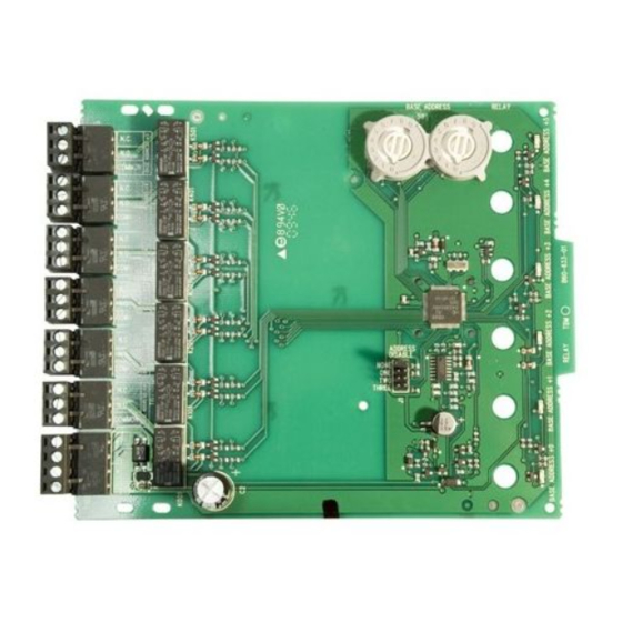
NFXI-RM6
Six Relay Control Module
SPECIFICATIONS
Normal Operating Voltage:
Stand-By Current:
Alarm Current:
Temperature Range:
Humidity:
Dimensions:
Maximum IDC Wiring Resistance:
Accessories:
Wire Gauge:
Relay Current:
RELAY CONTACT RATINGS:
CURRENT RATING
2 A
3 A
2 A
0.46 A
0.7 A
0.9 A
0.5 A
0.3 A
BEFORE INSTALLING
This information is included as a quick reference installation guide. If the
modules will be installed in an existing operational system, inform the op-
erator and local authority that the system will be temporarily out of service.
Disconnect the power to the control panel before installing the modules. This
system contains static sensitive components. Always ground yourself with a
proper wrist strap before handling any circuits so that static charges are re-
moved from the body. The housing cabinet should be metallic and suitably
grounded.
NOTICE: This manual should be left with the owner/user of this equipment. This
manual refers only to installations conforming to EN54 requirements.
GENERAL DESCRIPTION
The NFXI-RM6 Six Relay Control Module is intended for use in an intelligent
alarm system. Each module is intended for Form-C switching applications,
which do not require wiring supervision for the load circuit. A single isolated
set of dry relay contacts is provided for each module, which is capable of
being wired for either normally open or normally closed for each operation.
Each NFXI-RM6 module also has panel controlled tri-color (green, red and
amber) LED indicators. The panel can cause the LEDs to blink, latch on, or
latch off. The module also provides short circuit isolators to prevent shorts on
the fire detection and alarm system loop from disabling more than one device
on the intelligent loop.
ADDRESSES
In systems using CLIP (Communication Loop Intelligent Protocol) a pair of
rotary code switches is used to set the address of the first module from 01 to
94. The remaining modules are automatically assigned to the next five higher
addresses. Provisions are included for disabling a maximum of four unused
modules to release the addresses for use elsewhere.
In systems using Advanced Protocol a pair of rotary code switches is used to
set the address of the module from 01 to 159. Only one address is used for the
entire multi-module with sub-addresses completing the remaining addresses.
NO-460-024
15-29 VDC
1.45 mA
32 mA (assumes all six relays have been switched once and all six LEDs solid on)
-10°C to 55°C
10 to 93% Non condensing
17.3cm H x 14.7cm W x 3.2cm D
40 ohms
Suitably grounded metallic cabinet
0.8mm 2 - 3.25mm 2
30 mA/Relay Pulse (15.6 mS pulse duration) pulse under panel control
MAXIMUM VOLTAGE
25 VAC
30 VDC
30 VDC
30 VDC
70.7 VAC
125 VDC
125 VAC
125 VAC
LOAD DESCRIPTION
PF = 0.35
Resistive
Resistive
(L/R = 20ms)
PF = 0.35
Resistive
PF = 0.75
PF = 0.35
CONTENTS INCLUDE:
(6) 1 x 3 Terminal Blocks
(1) 1 x 4 Terminal Blocks
(4) Screws
COMPATIBILITY REQUIREMENTS
To ensure proper operation, this module shall be connected to a compatible
control panel only.
In order to comply with EN54-17 and EN54-18 requirements the modules
must be installed within a grounded, metal enclosure that is suitable for the
application. The CE marking label confirms compliance with CPD, and must
be applied to the module enclosure only once installation of the module in the
enclosure is completed. The label shall be mounted in a position that is visible
during installation and accessible during maintenance. The label shall not be
placed on screws or other easily removable parts.
1
Notifier by Honeywell.
Charles Avenue Burgess Hill
West Sussex RH15 9UF UK
APPLICATION
Non-coded
Non-coded
Coded
Non-coded
Non-coded
Non-coded
Non-coded
Non-coded
(2) 3.2 cm Stand offs
(2) Nuts
I56-3977-001
Advertisement
Table of Contents

Related Manuals for Honeywell NOTIFIER NFXI-RM6


Summary of Contents for Honeywell NOTIFIER NFXI-RM6
- Page 1 INSTALLATION AND MAINTENANCE INSTRUCTIONS NFXI-RM6 Notifier by Honeywell. Charles Avenue Burgess Hill Six Relay Control Module West Sussex RH15 9UF UK SPECIFICATIONS Normal Operating Voltage: 15-29 VDC Stand-By Current: 1.45 mA Alarm Current: 32 mA (assumes all six relays have been switched once and all six LEDs solid on) Temperature Range: -10°C to 55°C...
- Page 2 WIRING A dip switch is provided to disable a maximum of four unused modules NOTE: All wiring must conform to applicable local codes, ordinances, and in CLIP. Modules are disabled from the highest address and work down- regulations. ward. If two modules are disabled, the lowest four addresses will be Install module wiring in accordance with the job drawings and appropri- functional, while the highest two will be disabled.
- Page 3 ISTRUZIONI DI INSTALLAZIONE E MANUTENZIONE NFXI-RM6 Notifier by Honeywell. Modulo di controllo a sei relè Charles Avenue Burgess Hill West Sussex RH15 9UF UK SPECIFIChE Tensione normale di esercizio: 15-29 VDC Corrente di riserva: 1,45 mA Corrente di allarme: 32 mA (a condizione che tutti e sei i relè siano stati attivati una volta e che tutti e sei i LED siano accesi) Intervallo di temperatura: da -10°...
- Page 4 CABLAGGIO Per disabilitare un massimo di quattro moduli non utilizzati in CLIP, è NOTA: tutti i cablaggi devono essere conformi alle norme, ordinanze e dispo- disponibile una derivazione. I moduli vengono disabilitati a partire da sizioni locali applicabili. quello con l'indirizzo più alto e funzionano verso il basso. Se vengono Installare il cablaggio del modulo conformemente ai disegni e ai relativi disabilitati due moduli, i quattro moduli con l'indirizzo più...
- Page 5 INSTRUCCIONES DE INSTALACIÓN Y MANTENIMIENTO NFXI-RM6 Notifier by Honeywell. Charles Avenue Burgess Hill Módulo de control de seis relés West Sussex RH15 9UF UK ESPECIFICACIONES Tensión operativa normal: de 15 a 29 VCC Corriente en espera: 1,45 mA Corriente de alarma: 32 mA (asumiendo que los seis relés se han conmutado una vez y que el total de los seis LED están encendidos)
- Page 6 CABLEADO Se proporciona un conmutador selector para desactivar un máximo de NOTA: Todo el cableado debe cumplir con las normativas y los reglamentos cuatro módulos sin utilizar en CLIP. Los módulos se desactivan desde la y los códigos locales. dirección más alta de forma decreciente. Si hay dos módulos desactiva- Instale el cableado del módulo según los esquemas de trabajo y de ca- dos, las cuatro direcciones más bajas funcionarán, mientras que las dos bleado apropiados.
- Page 7 INSTALLATIONS- UND WARTUNGSANLEITUNG NFXI-RM6 Notifier by Honeywell. Charles Avenue Burgess Hill Steuermodul mit sechs Relais West Sussex RH15 9UF UK SPEZIFIKATION Betriebsspannungsbereich: 15 – 29 V DC Ruhestrom: 1,45 mA Alarmstrom: 32 mA (bei sechs angesteuerten Relais und sechs dauerleuchtenden LEDs) Temperaturbereich: -10 °C bis 55 °C...
- Page 8 VERDRAhTUNG Bei der CLIP-Funktion können über einen DIP-Schalter maximal vier HINWEIS: Die Verdrahtung muss gemäß den regionalen Auflagen, Richtlinien nicht verwendete Module deaktiviert werden. Die Deaktivierung der und Anforderungen ausgeführt werden. Module erfolgt abwärts, beginnend von der höchsten Adresse. Beim Installieren Sie das Modul gemäß...
Need help?
Do you have a question about the NOTIFIER NFXI-RM6 and is the answer not in the manual?
Questions and answers