Advertisement
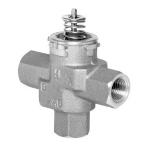
The VC hydronic valve consists of a valve body and replaceable characterized
cartridge assembly.
Depending on the valve model selected, they can be used with a VC2114 or
VC8114 series actuator to provide on-off flow control, or with a VC6930 or
VC7930 series actuator to provide proportional flow control. Two way bodies
may be plumbed in either direction. Three-way bodies may be used in either
diverting or mixing applications.
Replacing the cartridge rebuilds the valve. The valve body should be able to
stay in the pipes indefinitely.
VC actuators, ordered separately, use cam-operated cartridge travel to resist
water hammer. Limit switches prevent motor overrun. These actuators are
available with conformal coated printed circuit boards for humidity resistance.
The specifications following are nominal and conform to generally
accepted industry standards. Honeywell is not responsible for damages
resulting from misapplication or misuse of its products.
Operating Ambient:
32 to 150°F [0 to +65°C].
5-95% RH (non-condensing)
Fluid temperatures:
34 to 203°F [1 to 95°C]
Shipping and Storage Temperature:
-40 to 150°F [-40 to +65°C]
Atmosphere:
Non-corrosive, non-explosive.
Valve Materials:
Body of bronze Cartridge of Ryton (polyphenylene sulphide) and
Noryl (polyphenylene oxide)
O-ring seals of EPDM rubber
Stem of stainless steel
Pressure Rating:
Static - 300 psig [20 Bar] maximum.
Burst - 1500 psig [100 Bar]
Operating Differential and Close-off - 60 psi maximum [4 bar]
Stem Travel:
0.4 inches [10 mm]
Flow Characteristics: Linear or equal percentage, per Table 1.
Accessories and Replacement Parts:
40007029-002: Wrench for removing VC cartridge
VCZZ1100: 2-way linear flow characteristic cartridge
VCZZ1400: 2-way equal percentage cartridge
VCZZ1500: 2-way equal percentage cartridge, very low Cv
VCZZ1600: 2-way equal percentage cartridge, low Cv
VCZZ6100: 3-way linear flow characteristic cartridge
272866B: Flush caps for system cleaning, 10 per pack
2003.02.24
© Honeywell Limited.
Cartridge Valve for Use with VC Series Actuators
SPECIFICATIONS
VCA,B,M, and N Series
68 [2-3/4]
68 [2-3/4]
94 [3-3/4]
94 [3-3/4]
D D
A
C
Figure 1 - Nominal dimensions in inches and millimetres
[4]
Dimension
mm Inches mm Inches mm Inches
Pipe Fitting Sizes
1/2" BSPP (int.) [2]
98
1/2" BSPT (int.)
3/4" BSPP (int.)
3/4" BSPT (int.)
94 3-11/16
3/4" BSPP (ext.)
112 4-7/16
22mm Compression [3]
94 3-11/16
1" BSPP (int.)
1" BSPP (ext.)
95 3-11/17 114 4-7/17 137 5-11/33
1" BSPT (int.)
94 3-11/16
28mm Compression [3]
116 4-9/16
NORTH AMERICA STANDARD MODELS
3/8" FLARE [1]
98
1/2" SWEAT
89
1/2" FLARE [1]
1/2" INVERTED FLARE [1]
98
1/2" NPT (int.)
3/4" NPT (int.)
3/4" SWEAT
94 3-11/16
1" NPT (int.)
1" SWEAT
1-1/4" SWEAT
110 4-5/16 118 4-5/8 142
1-1/4" NPT (int.)
[1] No adapter
[2] 15 mm compression
[3] Nuts and olives not included
[4] All models not available in all countries
Table 1: VC Valve assembled dimensions
94 [3-3/4]
94 [3-3/4]
90 [3-9/16]
90 [3-9/16]
A
B
B
AB
C
C
D
E
3-7/8
111 4-3/8
136 5-11/32
130
5-1/8
113 4-7/16
140
5-1/2
136 5-11/32
136 5-11/32
113 4-7/16
147 5-13/16
3-7/8
136 5-11/32
3-1/2
130
5-1/8
111 4-3/8
3-7/8
136
5-11/32
130
5-1/8
132 5-3/16
113 4-7/16
136
5-11/32
5-5/8
Form No. 95C-10919
E E
Advertisement
Table of Contents

Related Manuals for Honeywell VCA Series


Summary of Contents for Honeywell VCA Series
- Page 1 SPECIFICATIONS 90 [3-9/16] 90 [3-9/16] The specifications following are nominal and conform to generally accepted industry standards. Honeywell is not responsible for damages resulting from misapplication or misuse of its products. Operating Ambient: 32 to 150°F [0 to +65°C]. Figure 1 - Nominal dimensions in inches and millimetres...
- Page 2 MODELS: BODIES: VCA,B,M,N ..., per table: 1 ACTUATORS (ORDER SEPARATELY) 2-way 1000 1100 1400 1500 1600 3-way 6000 6100 6400 6500 6600 Cartridge Cartridge Valve Valve Nominal Rating [8] Nominal Rating [8] Number Pipe Fitting Sizes Number Pipe Fitting Sizes VCZAF VCZME 1/2"...
- Page 3 INSTALLATION WHEN INSTALLING THIS PRODUCT: If assembling valve train on a bench, take care not to deform body with vice. Do not place the raised "H" logo between the jaws of the vice. 1. Read these instructions carefully. Failure to follow them could Excess jaw force can deform the body.
- Page 4 8. Reconnect leadwires or Molex™ connector if necessary. 9. Refill hydronic system or restore system flow by opening isolating valves. NOTE: Honeywell VC series hydronic valves are designed and tested 10. Restore power, and checkout operation of cartridge in valve, making sure for silent operation in properly designed and installed systems.
Need help?
Do you have a question about the VCA Series and is the answer not in the manual?
Questions and answers