
Related Manuals for Kinoton FP 30 D


Summary of Contents for Kinoton FP 30 D
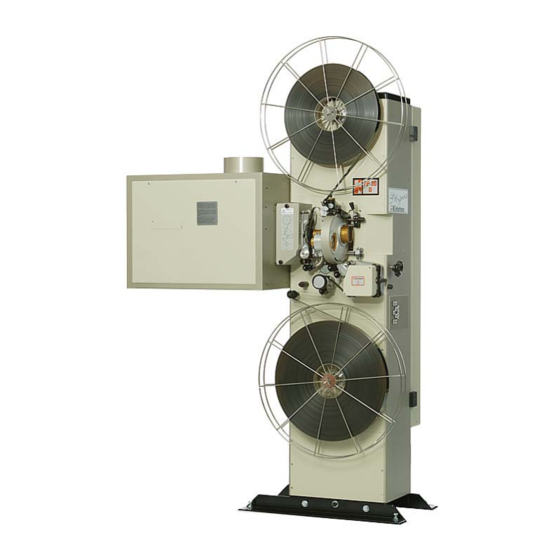
- Page 1 Operating Manual FP 30 D Projector DIGITAL CINEMA FILM TECHNOLOGY STUDIO TECHNOLOGY CUSTOMIZED SOLUTIONS 360° DISPLAY SYSTEMS...
- Page 3 FP 30 D Preface Dear customer, this operating manual will help you get acquainted with the projector and to make use of its possible applications in accordance with the requirements. This operating manual includes important hints for a safe, proper, correct and economic operation.
- Page 4 This operating manual – even in extracts – may only be reprinted or otherwise copied with special, written permission from KINOTON GmbH. Editor responsible for the contents: KINOTON GmbH Editing and layout: Carmen Auer - KINOTON GmbH Hints / Own Notes...
-
Page 5: Table Of Contents
FP 30 D Contents Safety . . . . . . . . . . . . . . . . . . . . . . . . . . . . . . . . . . . . . . . . .1 Safety Notes . - Page 6 FP 30 D Function and Components . . . . . . . . . . . . . . . . . . . . . .17 Components Overview .
- Page 7 Maintenance ........51 6.3.1 Drain and Refill Oil (Kinoton type 3672 oil):....52 6.3.2 Changing the Intermittent Oil .
- Page 8 FP 30 D ........
-
Page 9: Safety
FP 25/30/50 D / FP 10/20/30/50 A Safety 1 .1 Safety Notes 1 .1 .1 General Hints » Read this operating manual before operating the projector. » This operating manual is to be kept with the projector at all times. »... -
Page 10: Intended Purpose
Intended Purpose The projector is suitable to reproduce 35 mm film images and sound. Any other or further use is not classified as an “intended purpose”. KINOTON cannot be held liable for any damage resulting from different or extended operation. -
Page 11: Explanations Of Symbols And Notes
FP 25/30/50 D / FP 10/20/30/50 A 1 .2 Explanations of Symbols and Notes Throughout this manual you will find the following symbols: DANGER This symbol indicates an imminent threat of danger to life and personal health. Disregarding this warning can result in serious personal injuries or highly dangerous injuries. -
Page 12: Special Hazard Points
FP 25/30/50 D / FP 10/20/30/50 A 1 .3 Special Hazard Points 1 .3 .1 Electric Power Hazards DANGER S The access to power supply must always be kept closed. Only authorized service personnel may access this area. S Installation according to the local electrical code and regulations an work on the electrical supply conductors or circuits must only be done by qualified technical personnel. -
Page 13: Lamphouse Hazards
FP 25/30/50 D / FP 10/20/30/50 A 1 .3 .2 Lamphouse Hazards 1 .3 .2 .1 Broken Glass In cold condition the xenon lamp has an inner pressure of about 8 to 10 bar (145 psi) and in hot condition of about 30 bar (435 psi). When a xenon lamp bursts, broken glass can cause suffer injury to face, eyes and arteries. -
Page 14: Preventing Projector Damage
Therefore, avoid touching the coated lens surface. To remove dust on the lens, use a soft dry cloth (Cleaning set from Kinoton). Do not use a damp cloth, detergent solutions or thinner. 1 .5... -
Page 15: Protective Devices
FP 30 D 1 .6 Protective Devices All existing safety devices must be checked regularly 1 .6 .1 Main Switch In case of an emergency, you can switch off the projector using the main switch (under the projector door). Push the switch to position “0”. The red lamp in the switch turns off. - Page 16 FP 30 D Issue: 05/2011...
-
Page 17: Transportation And Installation / Mounting
Although most parts are delivered with a protective cover, you have to clean the projector and its components before the first start. 2 .2 Delivery or Equipment variations » Projector FP 30 D » Lamphouse - up to 2000 W - up to 7000 W »... -
Page 18: Installation
U Do not use unit parts as climbing aid. U The electrical connections have to be in accordance with local regulations and be installed professionally. U All installation should only be carried out by Kinoton service. 2 .3 .1 Place of Installation, Place of Operation »... -
Page 19: Important Hints For Installation
FP 30 D 2 .3 .2 Important Hints for Installation Projector Dimensions 4000 m 2000 m 600 m 10° 10° 1200 1426 Issue: 05/2011... -
Page 20: Additional Installation Hints
FP 30 D 2 .3 .3 Additional Installation Hints ATTENTION U The 16 PE lines have to be high-flexible to derive the high-frequency ignition voltage. U Do not use the wires in the lamphouse cable to connect the additional dowser. -
Page 21: Mounting
FP 30 D 2 .4 Mounting 2 .4 .1 Filling with Oil NOTE Use only Kinoton type 3672 oil. Intermittent movement (Maltese cross) Oil gauge glass with oil level rings (red and green) Oil gauge cap ... -
Page 22: Installing And Connecting The Lamphouse Components
FP 30 D 2 .4 .2 Installing and Connecting the Lamphouse Components NOTE Z Connecting the lamphouse should be carried out by service personnel. Z The installation and adjustment of the xenon bulb and the adjustment of the intensity of currents is described in the lamphouse manual. -
Page 23: Projector Terminal Strips
FP 30 D 2 .4 .4 Projector Terminal Strips The whole terminal strip unit in the projector can be designed with 3 parts. The number of parts depend on the projector’s design: Terminal strip x1 - main terminal strip (red arrow) - is normally mounted. - Page 24 FP 30 D Issue: 05/2011...
-
Page 25: Function And Components
FP 30 D Function and Components The FP 30 D projector is suitable to reproduce 35 mm film and sound formats in small, medium and large cinemas. » The film is transported through the projector from the top to the bottom. -
Page 26: Components Overview
FP 30 D 3 .1 Components Overview Projector housing with door Take-off friction (option) Lamphouse Shutter housing and film gate Ä Lens turret (option) Å Reverse-scan sound device Æ operating panel Take-up friction (option) ... -
Page 27: Film Gate And Film Track
FP 25/30/50 D 3 .2 Film Gate and Film Track In the film gate the film is positioned precisely. By adjusting the film pressure skate you can optimize the picture steadiness. After threading the film, close the film track with the film pressure skate to guide the film. -
Page 28: The Dowser
FP 25/30/50 D 3 .2 .2 The Dowser The dowser opens or closes the path of xenon light to the film gate. Dowser Dowser rotation solenoid Light baffle Rotary shutter Ä Film gate with water cooling unit or fire protection plate ATTENTION If the dowser does not close while the projector is stopped, the film will burn. -
Page 29: Single Aperture Plates (Only With Manual Lens Turret Or Lens Holder)
FP 25/30/50 D 3 .2 .3 Single Aperture Plates (only with manual lens turret or lens holder) Push the single aperture plate into the film gate until the stop is reached and the aperture plate snaps into position. 3 .2 .4 Aperture Changer (option, only with electronic lens turret) The aperture changer is suitable for automatically changing the aperture when the corresponding format key has been pressed. -
Page 30: Drive And Control
FP 25/30/50 D 3 .2 .4 .1 Drive and Control Aperture changer motor Aperture changer drive Aperture changer/lens turret control board 3 .2 .4 .2 Format Change with Three Lenses • Push on the operating panel. $The aperture changer places the selected aperture into the film gate and the matching lens in position. -
Page 31: Changing The Format Combination
FP 25/30/50 D 3 .2 .4 .4 Changing the Format Combination • The “select” function is activated by holding the control closed more than 2 seconds. $The turret will not rotate. The turret solenoid makes a clattering sound which means that a new format combination has been selected. -
Page 32: Lens Turret (Option)
• Fasten them with the knurled screws. NOTE Some lenses may require rings to support the rear section; these are available from Kinoton. • For easy film threading flip the position lever - the lens turret will move away from the film gate. -
Page 33: Electronically Controlled Lens Change (Option)
FP 25/30/50 D 3 .2 .6 .2 Electronically Controlled Lens Change (option) The electronically controlled lens turret is suitable to change the lens automatically when the corresponding format key has been pressed. Simultaneously the applicable aperture is changed too. Lens tubes with lenses ... -
Page 34: Focusing
FP 25/30/50 D 3 .2 .7 Focusing To adjust the focus for a sharp picture on the screen, you have to move horizontally the whole lens turret or lens holder. This operation can be done manually or electroni- cally controlled. 3 .2 .7 .1 Manual Focusing with Lens Turret / Lens Holder •... -
Page 35: Rotating Shutter
FP 25/30/50 D 3 .2 .8 Rotating Shutter The rotating shutter interrupts the projection light once during the film transport and once during the picture standstill. (48 interruptions a second at 24 pictures a second). The shutter is mounted on a shaft which is driven from the intermittent movement via a fibre gear. -
Page 36: Intermittent Sprocket
FP 25/30/50 D 3 .2 .9 Intermittent Sprocket The intermittent sprocket (arrow) is a very precise sprocket. It transports the film step by step through the film gate. The intermittent sprocket is driven via the intermittent sprocket drive by the main drive motor. -
Page 37: Constant Speed Sprockets
FP 25/30/50 D 3 .2 .11 Constant Speed Sprockets Sprockets are designed to transport the film continuously. The teeth of the sprocket engage the perforations of the film. Both sprockets provide for equal loops before and after the film gate. ... -
Page 38: Reverse-Scan Sound Device
FP 25/30/50 D Operating a Pad Shoe Gently The pad shoe has a brass bearing tube which pivots on the pad shoe shaft, and is positioned with a ring nut and a spring. To avoid damaging the pad shoe and causing the brass tube to revolve within the pad shoe, the pad shoe must be handled gently. -
Page 39: Reverse-Scan Sound Device Analog And Optional Dolby Digital
FP 25/30/50 D 3 .3 .2 Reverse-Scan Sound Device Analog and optional DOLBY Digital (upgradeable) The Reverse-Scan Sound Device contains an analog sound reader and optionally a Dolby digital reader. NOTE Z An only analog sound device is upgradeable with DOLBY digital. Z The reverse scan sound head is delivered factory checked and adjusted. -
Page 40: Sound Tracks On The Films
FP 25/30/50 D 3 .3 .3 Sound Tracks on the Films The analog sound is printed as two wavy lines on the film. The height of the amplitude signifies loud- ness, frequency signifies pitch. The Dolby digital sound information (DOLBY SR·D) is encoded between the perforations. -
Page 41: Drive And Electronic Components
FP 30 D 3 .6 Drive and Electronic Components NOTE Z In this chapter you will get an overview of the components in the projector. Z All work on drives and electronics should only be carried out by experts. ... -
Page 42: Main Drive
FP 30 D 3 .6 .1 Main Drive Main drive motor Intermittent movement directly flanged on the main drive motor Fibre gear: drives shutter and sprockets Upper/feed sprocket shaft & cog Ä Upper chain Å Lower chain Æ... -
Page 43: Intermittent Movement (Also Called A Maltese Cross Or A Geneva Movement)
FP 30 D 3 .6 .2 Intermittent Movement (also called a Maltese Cross or a Geneva Movement) To pull the film down one picture at a time the intermittent sprocket has to move the film ahead by four sprocket teeth (¼ of a complete rotation): - A motor rotates the cam continuously. -
Page 44: Friction Drives
FP 30 D 3 .6 .3 Friction Drives The friction is a shaft, which is driven with a constant turning moment. The take-off friction is not necessary to be driven, because the take-up friction - which is driven by the main drive motor - pulls the film from the upper take-off shaft. -
Page 45: Electronically Controlled Friction Drives (Option)
Friction shaft NOTE Z Projectors with an optional reverse running unit (FP 30 D-RR) must be equipped with two motor drives. Z Normally the set value is preset and have not be changed. Nevertheless, if adjust- ments are necessary, they should be carried out by service engineers. -
Page 46: Relay Control Board, Frequency Inverter, Power Supply Unit
FP 30 D 3 .6 .4 Relay Control Board, Frequency Inverter, Power Supply unit Relay control board 81-34 Switch 24/25 fps 24 V power supply Frequency inverter 3 .6 .5 LED Power Supply Board for the Reverse-Scan Sound Device... -
Page 47: Operating Elements
FP 30 D Operating Elements 4 .1 Main Switch Main switch in position I: Current transfer is switched on => the switch lights up red. Main switch in position 0: Current transfer is switched off => the switch is off. -
Page 48: Friction Control
FP 30 D 4 .3 Friction Control NOTE Depending on your demands, the size of friction can vary. Generally you can select between a large (e. g. 4000 m) and a small (e. g. 600 m) friction. Selection for take-up friction... -
Page 49: Remote Control Panels (Option)
FP 30 D 4 .4 Remote Control Panels (option) BWR Control Panel Auditorium Panels 4 .4 .1 “BWR” Control Panel House light ON Focusing + (option) Stage light ON House light HALF Stage light STOP Focusing - (option) Dowser OPEN... -
Page 50: Auditorium Panel
FP 30 D 4 .4 .2 Auditorium Panel House light ON Stage light ON Focusing + (option) House light HALF Stage light STOP Focusing - (option) House light STOP Stage light OFF Frame UP Frame DOWN House light OFF AUTO... -
Page 51: Operation And Troubleshooting
FP 30 D Operation and Troubleshooting 5 .1 Switch On and Start the Projector • Switch on the external power supply for the performance room. • Switch on the main switch (position “I”). $The switch illuminates red. • Thread the film (see chapter 5.3). -
Page 52: Threading For Projection Operation
FP 30 D 5 .3 Threading for Projection Operation • Put the full reel on the upper reel from take-off shaft or prepare the platter system. friction • Open the sprocket pad shoe. - Thread the film in the feed... -
Page 53: Troubleshooting
- friction shafts are running dry - lubricate with Cardan oil Oil leak - wrong oil - use Kinoton 3672 oil - too much oil - reduce oil quantity - oil tube / vent is blocked - clean oil tube / vent... - Page 54 FP 25/30/50 D / FP 10/20/3050 A Error Cause Solution Picture moves - ceramic discs are blocked or dirty - remove and clean horizontally - ceramic discs are worn [rare] - change (waves) Picture moves - skate pressure isn’t adjusted - adjust vertically (jumps) correctly...
-
Page 55: Analog Sound
FP 25/30/50 D / FP 10/20/3050 A 5 .4 .4 Analog Sound Error Cause Solution No sound / some - sound processor failure - check plugs and power; call service channels missing - amplifier failure - check if sound track is threaded on the correct side - speaker failure - check / replace exciter lamp... - Page 56 FP 25/30/50 D / FP 10/20/3050 A Issue: 05/2011...
-
Page 57: Cleaning / Maintenance / Repair
FP 25/30/50 D / FP 10/20/3050 A Cleaning / Maintenance / Repair 6 .1 General Hints ATTENTION U Any work on the electric supply wiring must be carried out by electricians. U Make sure that nobody starts the projector while you are working on it. For all maintenance, cleaning and repair you must disconnect the projector from its power supply (switch off the main switch). - Page 58 FP 25/30/50 D / FP 10/20/3050 A Every 2 weeks Component What is to do? ceramics roller Remove the ceramics rollers and then remove the dirt in the holes by using air pressure. Clean the ceramics roller with a alcohol moisturized cloth. Every 3 months Component What is to do?
-
Page 59: Maintenance
What is to do? lens holder Lubricate the lens holder guidance with Cardan oil, type 8657 fibre gear / Lubricate with Kinoton EL 4854 grease. shutter shaft worm chains Lubricate with Esso universal oil. aperture changer Clean the part of the shaft above the film path with a cloth,... -
Page 60: Drain And Refill Oil (Kinoton Type 3672 Oil)
6 .3 .2 Changing the Intermittent Oil Procedure to change oil (Use Kinoton type 3672 oil only.): • Remove the oil gauge cap and remove hose from clip. Move open end of hose down into empty container. Let the oil drain out completely. Add oil through the hose. The oil level must be between the red and green ring. -
Page 61: Adjusting The Film Pressure Skate
FP 25/30/50 D / FP 10/20/3050 A 6 .4 .2 Adjusting the Film Pressure Skate The correct adjustment of the film pressure skate is mandatory in order to run the film easefully and steady-going and with minor wear and tear of projector and film copy. •... -
Page 62: Adjusting The Height Of The Film Pressure Skate
FP 25/30/50 D / FP 10/20/3050 A 6 .4 .3 Adjusting the Height of the Film Pressure Skate The film pressure skate has to be adjusted so that it rides perfectly on the film gate and the intermittent sprocket. • Loosen the setscrew (black arrow). •... -
Page 63: Changing The 35 Mm Film Runner Strips
FP 25/30/50 D / FP 10/20/3050 A 6 .4 .4 Changing the 35 mm Film Runner Strips • Loosen the knurled fastening screws and remove the old runner strips and insert the new runner strips. $They must lay in parallel to the vertical film gate edges. The small spring-suspended ceramic rollers must have a free clearance. -
Page 64: Adjusting The Lens Holder
FP 25/30/50 D / FP 10/20/3050 A 6 .4 .5 Adjusting the Lens Holder • For setting up lenses, set scale in the mid-position. • Loosen the clamping screw (arrow) and push the lens into the holder until picture is sharp (basic adjustment). •... -
Page 65: Adjusting The Tension Of The Pad Shoe Spring
FP 25/30/50 D / FP 10/20/3050 A 6 .4 .7 Adjusting the Tension of the Pad Shoe Spring • Loosen the locking screw (black arrow) with an Allen key. • Adjust the tension of the spring by turning the adjusting ring (white arrow) clockwise with a special tool. -
Page 66: Changing And Lubricating The Felt Disk Of The Mechanical Friction
FP 30 D 6 .4 .10 Changing and Lubricating the Felt Disk of the Mechanical Friction • Remove the knurled nut, the spring, the friction plate and the felt disk on the friction shaft (black arrows). • Once in a year the felt disk should be put in a Cardan oil bath. If the felt disk is worn (surface is hardened) it has to be changed and oiled. -
Page 67: Tension The Chains
FP 30 D 6 .4 .12 Tension the Chains NOTE The chains must not be taut, but they must not flap during the movement. The chain should be tension in a way that a distance of about 1 cm remains, when the chain is pressed towards the bottom sprocket (arrow). - Page 68 FP 30 D Lower Chain • Loosen the centre Allen locking screw on the eccentric gear (arrow) and move the eccentric gear until the chain tension is correct. • Tighten the lock screw again. Issue: 05/2011...
-
Page 69: Parts And Wearing Parts
FP 30 D Parts and Wearing Parts 7 .1 Parts for the Film Gate Part Figure Order Number Film runner strips, white 5322 463 10021 Film runner strips, Novotex brown 5322 463 10023 Knurled screw for fastening the film runner strips... - Page 70 FP 30 D Fig . 1B Figure 1 Fig . 1A Fig . 1E Fig . 1F Fig . 1C Fig . 1D Issue: 05/2011...
- Page 71 FP 30 D Figure 2 Fig . 2A Fig . 2B Fig . 2C Figure 3 Fig . 3A Issue: 05/2011...
- Page 72 FP 30 D Figure 4 4A + 4B 4C +4D 4A + 4B Fig . 4A Fig . 4B Fig . 4C Fig . 4D Fig . 4E Fig . 4F Issue: 05/2011...
-
Page 73: Parts For Motors And Drives
Oil gauche glass 5322 532 70114 Knurled nut M8 1000 505 17006 Spring for Kinoton friction 5322 492 50064 Felt disk for Kinoton friction 1000 532 57007 Projector oil 3672/00, 1 L 1000 390 27006 Figure 5 Figure 6 Fig . 7B Figure 7 Fig . -
Page 74: Film Spools
FP 30 D 7 .6 Film Spools Part Code number Film spool Ø 9 mm, 600 m film 0040 060 00050 Film spool Ø 12.7 mm, 1800 m film 0040 060 00765 Film spool Ø 12.7 mm, 2000 m film 0040 060 00770 Film spool Ø... -
Page 75: Mm Apertures For Aperture Changer
FP 30 D 7 .8 35 mm Apertures for Aperture Changer Part Code Number Triple aperture shaped 1000 451 17012 Triple aperture for filing 1000 451 17016 Hole aperture to adjust the frame center 1000 451 17017 Triple aperture dimension smaller than specified... -
Page 76: Adapter Rings For 35 Mm Lenses
FP 30 D 7 .10 Adapter Rings for 35 mm Lenses Part Code Number Adapter ring 1 for ISCO Cinemascope Ultra-Star 55 / 60 0070 410 00003 Adapter ring 2 for Schneider Super-Cinelux 50 / 52,5 / 55 / 57.5 / 60ISCO... -
Page 77: Technical Data, Circuit Diagrams And Plans Of Terminal Connections
FP 30 D Technical Data, Circuit Diagrams and Plans of Terminal Connections 8 .1 Technical Data 8 .1 .1 Projector Name Film Projector Type FP 30 D Machine No. See data plate on housing. Connecting Data Power supply 120 V /230 V... -
Page 78: Plans Of Terminal Connections
FP 30 D 8 .2 Plans of Terminal Connections 8 .2 .1 Relay Control Board 8134-3 Issue: 05/2011... -
Page 79: Projector Terminal Strips
FP 30 D 8 .2 .2 Projector Terminal Strips The whole terminal strip unit in the bottom of the projector can be built out of 3 parts. The number of parts (1 - 3) depends on the projector’s design: - Terminal strip x1 (main terminal strip) is normally mounted. -
Page 80: Terminal Strip X2 (Projector Functions Terminal Strip)
FP 30 D 8 .2 .2 .2 Terminal Strip x2 (projector functions terminal strip) No . Connection (source) Color Ø EMK 1 connection: No . (bk) Relay + 24 V - 24 V Start FORWARD GND / com 1 + 2... -
Page 81: Terminal Strip X3 (Auditorium Function Terminal Strip, Optional)
FP 30 D 8 .2 .2 .3 Terminal Strip x3 (auditorium function terminal strip, optional) No . Connection / Function EMK 1 connection: No . (bk) Curtain COM Curtain OPEN Curtain CLOSE House light COM House light ON House light HALF... -
Page 82: Sound Output On 8-Pole Terminal Strip
FP 30 D 8 .2 .3 Sound Output on 8-pole Terminal Strip Solar cell connection Solar cell connection Solar cell connection Shield Sound output left - (yellow) Sound output left + (brown) Sound output right - (white) Sound output right +... -
Page 83: Circuit Diagrams
FP 30 D 8 .3 Circuit Diagrams 8 .3 .1 FP 30 D L e n s T u r r e t B o a r d MATRIX SENSOR FU PARAMETERS C E 1 = 0 1 C E 2... -
Page 84: Lamphouse 230 V Mains Voltage
FP 30 D 8 .3 .2 Lamphouse 230 v Mains voltage L a m p f a n F a n m o t o r H o u r c o u n t e r I g n i t i o n U n i t 4 0 6 0 D C... -
Page 85: Lamphouse 120 V Mains Voltage
FP 30 D 8 .3 .3 Lamphouse 120 v Mains voltage L a m p f a n F a n m o t o r H o u r c o u n t e r S K 1... - Page 86 FP 30 D Issue: 05/2011...
- Page 87 EC Declaration of Conformity Kinoton GmbH Company name Address: Industriestr. 20a, D-82110 Germering Machine designation: Cinema Projector FP 30 D Machine type: Maschine serial number: A7541 Relevant EC stipulations: Machine regulation 2006/42/EG Low voltage regulation 2006/95/EG EMC regulation 2004/108/EG Standards:...
Need help?
Do you have a question about the FP 30 D and is the answer not in the manual?
Questions and answers