
Related Manuals for Kinoton FP 38 E Premiere


Summary of Contents for Kinoton FP 38 E Premiere
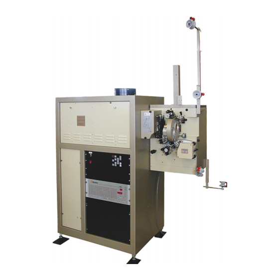
- Page 1 Operating Manual FP 50 E PREMIERE Console Projector DIGITAL CINEMA FILM TECHNOLOGY STUDIO TECHNOLOGY CUSTOMIZED SOLUTIONS 360° DISPLAY SYSTEMS...
- Page 3 FP 50 E Preface Dear customer, this operating manual will help you get acquainted with the projector and to make use of its possible applications in accordance with the requirements. This operating manual includes important hints for a safe, proper, correct and economic operation.
- Page 4 This operating manual – even in extracts – may only be reprinted or otherwise copied with special, written permission from KINOTON GmbH. Editor responsible for the contents: KINOTON GmbH Editing and layout: Carmen Auer - KINOTON GmbH Hints / Own Notes...
-
Page 5: Table Of Contents
FP 50 E Contents Safety . . . . . . . . . . . . . . . . . . . . . . . . . . . . . . . . . . . . . . . . .1 Safety Notes . - Page 6 FP 50 E Connecting the Projector......14 Connecting the Non-Rewind System to the Projector ..14 Function and Components .
- Page 7 FP 50 E DTS/SDDS Reader ....... . . 29 Film Cleaner (option)....... . 29 Film Transport Systems .
- Page 8 FP 50 E Operation and Troubleshooting . . . . . . . . . . . . . . . . . .47 Switch on and Start Projector / Stop and Switch off Projector .
- Page 9 FP 50 E 6.4.6 Changing a Constant Speed Sprocket / Pad Shoe ....63 6.4.7 Adjusting the Tension of the Pad Shoe Spring ....64 6.4.8 Adjusting the Distance between Pad Shoe and Sprocket .
- Page 10 FP 50 E Technical Data, Circuit Diagrams and Plans of Terminal Connections . . . . . . . . . . . . . . . . . .83 Technical Data .
-
Page 11: Safety
FP 25/30/38/50 E Safety 1 .1 Safety Notes 1 .1 .1 General Hints » Read this operating manual before operating the projector. » This operating manual is to be kept with the projector at all times. » For safe and trouble free operation of the projector a good working knowledge of basic safety regulations and the projector’s correct use is required. -
Page 12: Intended Purpose
Intended Purpose The projector is suitable to reproduce film images and sound. Any other or further use is not classified as an “intended purpose”. KINOTON cannot be held liable for any damage resulting from different or extended operation. As part of the “intended purpose” these tasks must be performed: »... -
Page 13: Special Hazard Points
FP 25/30/38/50 E NOTE This symbol indicates where notes, user tips and useful information can be found. They serve to help use the projector to its fullest. Always wear face protection when changing the xenon lamp. Always wear protection gloves when changing the xenon lamp. Always wear protection jacket (Kevlar) when changing the xenon lamp. -
Page 14: Warning Risk Of Fire
FP 25/30/38/50 E 1 .3 .2 Warning Risk of Fire DANGER S Do not cover the projector or the lens with any material while the projector is in operation. S In the event of fire, use sand, CO , or dry powder fire extinguishers; never use water on an electrical fire. -
Page 15: Mechanical Danger
Therefore, avoid touching the coated lens surface. To remove dust on the lens, use a soft dry cloth (Cleaning set from Kinoton). Do not use a damp cloth, detergent solutions or thinner. Issue: 08/2012... -
Page 16: Service
Copyright Copyright of this manual remains in possession of KINOTON. This manual is intended for the user and its staff only. It contains regulations and operating notes that must not be copied, reproduced or otherwise transmitted, in whole or in part. -
Page 17: Protective Devices
FP 50 E 1 .6 Protective Devices All existing safety devices must be checked regularly 1 .6 .1 Main Switch In case of an emergency, you can switch off the projector using the main switch (under the projector door). Push the switch to position “0”. The red lamp in the switch turns off. 1 .6 .2 IR Reflex Film Break Sensor The film break sensor (arrow) switches off the projector when no film is passing the sen-... -
Page 18: Lamphouse Door Switch
FP 50 E 1 .6 .4 Lamphouse Door Switch On both sides door switches (arrows) are mounted in the lamphouse frame. The xenon lamp only ignites when both lamphouse side doors are closed. ATTENTION Never activate the lamphouse via the rectifier. 1 .6 .5 Lamphouse Airflow Switch As soon as the projector is switched on, the radial blower starts the operation. -
Page 19: Transportation And Installation / Mounting
FP 50 E Transportation and Installation / Mounting 2 .1 Transportation » The projector is completely (with mounted lamphouse (up to 2000 W), without lamphouse (2000 W - 7000 W) mounted on a pallet and secured with screws. » With delivery to countries over-seas the projector secured on the pallet is packed in a wooden crate. -
Page 20: Installation
U Do not use unit parts as climbing aid. U The electrical connections have to be in accordance with local regulations and be installed professionally. U All installation should only be carried out by Kinoton service. 2 .3 .1 Place of Installation, Place of Operation »... -
Page 21: Important Hints For Installation
FP 50 E 2 .3 .2 Important Hints for Installation Projector Dimensions Issue: 08/2012... -
Page 22: Additional Installation Hints
FP 50 E 2 .3 .3 Additional Installation Hints ATTENTION U The 16 PE lines have to be high-flexible to derive the high-frequency ignition voltage. U Do not use the wires in the lamphouse cable to connect the additional dowser. Lay the dowser connection in the lamphouse tube as short as possible. -
Page 23: Connecting The Water Cooling (Option)
FP 50 E 2 .3 .5 Connecting the Water Cooling (option) ATTENTION U A water flow of 2 to 3 l/min is needed to get a water temperature of 18° C ± 2° C (64° F ± 10° F). U The water temperature should not be less than 16° C, otherwise water can con- dense on pipes, cables and film running components and finally results in damage of the film material. -
Page 24: Connecting The Projector
FP 50 E 2 .4 Connecting the Projector Connect the projector to the mains current (insert the plug): » 230 / 400 V or » 120 / 208 V. NOTE You will find plans of terminal connections in chapter 8.2. 2 .5 Connecting the Non-Rewind System to the Projector Install the non-rewind system. -
Page 25: Function And Components
FP 50 E Function and Components 3 .1 Components Overview 3 .1 .1 Projection Drive The FP 50 E console projector is suitable to reproduce 35 mm films and sound for- mats in small, medium and large cinemas. » The film is transported through the projector from the top to the bottom. »... -
Page 26: Fp 50 E Variations
FP 50 E 3 .1 .4 FP 50 E Variations Operation with a platter system Projector head Á Extension arms with guide rollers for running with a platter system  Lamphouse à Operating panel Ä Electronic components / rectifier / automation system (here EMK 1) Å... -
Page 27: Projector Head
FP 50 E 3 .1 .5 Projector Head Shutter housing Á Film gate with film pressure skate and aperture changer (option)  Intermittent sprocket à Bottom / holdback sprocket Ä Feed sprocket Å Lens turret (option) Focusing knob ... -
Page 28: Film Gate And Film Track
FP 25/30/50 E 3 .2 Film Gate and Film Track In the film gate the film is positioned precisely. By adjusting the film pressure skate you can optimize the picture steadiness. After threading the film, close the film track with the film pressure skate to guide the film. -
Page 29: The Dowser
FP 25/30/50 E 3 .2 .2 The Dowser The dowser opens or closes the path of xenon light to the film gate. Opening the dowser can be done by pushing the corresponding button on the operating panel or automatically controlled by an automation system and a cue foil on the film. -
Page 30: Single Aperture Plates (Only With Manual Lens Turret Or Lens Holder)
FP 25/30/50 E 3 .2 .3 Single Aperture Plates (only with manual lens turret or lens holder) Push the single aperture plate into the film gate until the stop is reached and the aperture plate snaps into position. 3 .2 .4 Aperture Changer (option, only with electronic lens turret) The aperture changer is suitable for automatically changing the aperture when the corresponding format key has been pressed. -
Page 31: Drive And Control
FP 25/30/50 E 3 .2 .4 .1 Drive and Control Aperture changer motor Á Aperture changer drive  Aperture changer/lens turret control board 3 .2 .4 .2 Format Change with Three Lenses • Push on the operating panel. $The aperture changer places the selected aperture into the film gate and the matching lens in position. -
Page 32: Changing The Format Combination
FP 25/30/50 E 3 .2 .4 .4 Changing the Format Combination • The “select” function is activated by holding the control closed more than 2 seconds. $The turret will not rotate. The turret solenoid makes a clattering sound which means that a new format combination has been selected. -
Page 33: Lens Turret (Option)
NOTE Some lenses may require rings to support the rear section; these are available from Kinoton. • For easy film threading flip the position lever - the lens turret will move away from the film gate. Make sure to put the lever fully back in position before project- ing! •... -
Page 34: Electronically Controlled Lens Change (Option)
FP 25/30/50 E 3 .2 .6 .2 Electronically Controlled Lens Change (option) The electronically controlled lens turret is suitable to change the lens automatically when the corresponding format key has been pressed. Simultaneously the applicable aperture is changed too. Lens tubes with lenses Á... -
Page 35: Focusing
FP 25/30/50 E 3 .2 .7 Focusing To adjust the focus for a sharp picture on the screen, you have to move horizontally the whole lens turret or lens holder. This operation can be done manually or electroni- cally controlled. 3 .2 .7 .1 Manual Focusing with Lens Turret / Lens Holder •... -
Page 36: Rotating Shutter
FP 25/30/50 E 3 .2 .8 Rotating Shutter The rotating shutter interrupts the projection light once during the film transport and once during the picture standstill. (48 interruptions a second at 24 pictures a second). The shutter is driven by an electronically controlled motor. ... -
Page 37: Constant Speed Sprockets
FP 25/30/50 E 3 .2 .11 Constant Speed Sprockets Sprockets are designed to transport the film continuously. The teeth of the sprocket engage the perforations of the film. Both sprockets provide for equal loops before and after the film gate. ... -
Page 38: Reverse-Scan Sound Device (Analog And Optional Dolby Digital / Upgradeable)
FP 25/30/50 E 3 .3 Reverse-Scan Sound Device (analog and optional DOLBY digital / upgradeable) Reverse-scan sound devices scan the sound track (analog and optional DOLBY digital) on the film via red LEDs. An only analog sound device is upgradeable with DOLBY digital. NOTE Z The reverse scan sound head is delivered factory checked and... -
Page 39: Sound Tracks On The Films
FP 25/30/50 E 3 .3 .2 Sound Tracks on the Films Analog sound is printed as two wavy lines on the film. The height of the amplitude signifies loud- ness, frequency signifies pitch. The Dolby digital sound information (DOLBY SR·D) is encoded between the perforations. - Page 40 FP 25/30/50 E Issue: 08/2012...
-
Page 41: Film Transport Systems
FP 50 E 3 .6 Film Transport Systems 3 .6 .1 Friction Shafts with Film Spools A friction is a shaft, which is driven with a constant turning moment. Take-off friction (non-driven) This “take-off clutch” provokes that a certain traction force is necessary to wind off the film. -
Page 42: Guide Roller Set For Operation
FP 50 E 3 .6 .2 Guide Roller Set for Operation with a Platter System (option) For operating with a non-rewind system a set of guide rollers on extension arms can be mounted on the projector head. - The extension arms of guide rollers are adjustable in length. - The guide rollers are movable and can be tilt according to the film guidance. -
Page 43: Drive Components In The Projector Head
FP 50 E 3 .7 Drive Components in the Projector Head NOTE Z In this chapter you will get an overview of the drive components. Z All work on drives should be carried out by experts. 3 .7 .1 Main Drive ... -
Page 44: Premiere Intermittent Sprocket Drive
FP 50 E 3 .7 .2 PREMIERE Intermittent Sprocket Drive Via pulses the main drive encoder counts quantity of film (transport unit = 1 picture), which is transported out of feed sprocket into film gate. If one “transport unit” is completely counted and shutter position is dark the motor of intermittent sprocket carries on film for one picture. -
Page 45: Other Electrical Components In The Projector Console
FP 50 E 3 .8 .2 Other Electrical Components in the Projector Console X1 main terminal strip Á Internal terminal strip with main fuse 6.3 A Â Relays: RUN, C/O, XENON Ã Mains contactor Ä Fuse 10 A Å Overload release 40 A ... -
Page 46: Xenon Sensor (Option)
FP 50 E Kinoton KEx 110 or KEx 170 Rectifier The electronic Kinoton rectifier are available with a power up to: - 110 A (KEX 110) - 170 A (KEX 170) for use for different mains voltages. The intensity of current for the xenon lamp can be set by turning a potentiometer or via the LDU unit’s program. -
Page 47: Lamphouse Components
FP 50 E 3 .9 Lamphouse Components Xenon bulb Á Anode (+) cable  Anode connecting bolt à Bulb support (up to 7,000 W only) Ä Mirror Å Mirror holders and protection shield Stabilizing magnet Ignition base ... -
Page 48: Xenon Unit
Z The xenon unit is factory-set positioned at the back of the lamphouse. Z The adjustment of the optical axis has to be carried out by authorised experts or service personnel from KINOTON. Z The small xenon unit can be equipped with xenon bulbs 1,000 to 2,000 W which will be easily screwed in. -
Page 49: Mirror
FP 50 E 3 .9 .3 Mirror Nowadays cold mirrors are mostly used. Because of their coating, heat can diffuse the mirror – the film gate gets a less range of heat but the full range of light. The following mirrors are available: »... - Page 50 FP 50 E Issue: 08/2012...
-
Page 51: Operating Elements
FP 50 E Operating Elements 4 .1 Projector Console Projector operating panel Á Auditorium operating panel (option) Â Main switch NOTE The operating panels can differ corresponding to the automation system and/or remote control. 4 .1 .1 Main Switch Main switch in position I: Current transfer is switched on =>... -
Page 52: Projector Operating Panel
FP 50 E 4 .1 .2 Projector Operating Panel Projector STOP Projector START Dowser CLOSE Dowser OPEN Framing UP Framing DOWN Focusing + Focusing - Projection speed Change-over switch Format CS (option) Format WS (option) Format NS (option Position the frame Format SELECT (option for 2 lens turret) Issue: 08/2012... -
Page 53: Auditorium Remote Operating Panel (Option)
FP 50 E 4 .1 .3 Auditorium Remote Operating Panel (option) Masking STOP Masking 1 Masking 2 Masking CS House light STOP House light OFF House light ON House light HALF Stage light STOP Stage light OFF Stage light ON Curtain STOP Curtain OPEN Curtain CLOSE... -
Page 54: Projector Lamphouse
FP 50 E 4 .2 Projector Lamphouse Ammeter Á Operating hour counter  Fuse (6.3 A) à Main switch Ä Press button: IGNITE 4 .2 .1 Ammeter The ammeter shows the set intensity of currents. » The small lamphouse (1000 to 2000 W) is equipped with a 100 A ammeter. »... -
Page 55: Main Switch
FP 50 E 4 .2 .4 Main Switch Toggle switch in position “I”: The xenon lamp is ON. The ventilation runs after when the xenon lamp turns off. Toggle switch in position “0”: The xenon lamp is OFF. Manually switch on or switch off •... -
Page 56: Rectifier
The intensity of current can be adjusted via a potentiometer. The adjusted intensity of currents can be read on the ammeter. Kinoton electronic rectifier (KEx 110/170) The intensity of current can be adjusted via a potentiometer or optionally via the LDU display unit. -
Page 57: Operation And Troubleshooting
FP 50 E Operation and Troubleshooting 5 .1 Switch on and Start Projector / Stop and Switch off Projector ATTENTION Do not stand too close on rotating film spools, because clothes, hair or other parts of your body can get winded up or trapped into the spools. Switch on and start the projector •... -
Page 58: Threading For Projection Operation
FP 50 E 5 .2 Threading for Projection Operation 5 .2 .1 General Threading • Put the full reel on the upper reel from take-off friction shaft or prepare the platter system. • Open the sprocket pad shoe. - Thread the film in the feed Feed sprocket sprocket (all perforations engaged in sprocket teeth). -
Page 59: Threading From A Non-Rewind / Platter System
FP 50 E 5 .2 .2 Threading from a Non-Rewind / Platter System General with film cleaner and DTS reader If a DTS reader is installed, but you do not use it for an operation then thread the film which comes from the non-rewind system via the upper guide roller of the DTS reader and then to the feed sprocket. -
Page 60: Different Projection Speeds
FP 50 E 5 .3 Different Projection Speeds NOTE Z The xenon lamp will be switched on when the film is running forwards (DIP 7 is OFF). If DIP 7 is ON the xenon lamp will ignite at the first projector start and will get off when projector is switched off. -
Page 61: Projecting At Varia Speed (Option)
FP 50 E 5 .3 .4 Projecting at VARIA Speed (option) At VARIA the projector runs in step mode - it projects forwards and optional reverse from 10 fps to 30 fps. Press “in“ activates the VARIA function - press “out” activates 24 fps. Select the desired projection speed of 10 - 30 fps by turning the VARIA rotary switch. -
Page 62: Troubleshooting
FP 25/30/38/50/75 E 5 .6 Troubleshooting 5 .6 .1 General Hints Even though we produce high quality, reliable equipment, there still can be problems due to incorrect operation, poor maintenance, incorrect procedures etc. This chapter has information about some common problems and about solving those problems. - Page 63 FP 25/30/38/50/75 E Error Cause Solution Picture moves - skate pressure isn’t adjusted correctly- - adjust vertically (jumps) - skate height isn’t adjusted correctly - adjust - film print defective [verify with test film] - get new print - skate is worn - change - intermittent sprocket damaged - change (service)
-
Page 64: Analog Sound
FP 25/30/38/50/75 E 5 .6 .4 Analog Sound Error Cause Solution No sound / some - sound processor failure - check plugs and power; call service channels missing - amplifier failure - check if sound track is threaded on the correct side - speaker failure - check / replace exciter lamp (standard... -
Page 65: Error Indication With Leds
FP 25/30/38/50/75 E 5 .7 Error Indication with LEDs 5 .7 .1 Interface Board Two red break LEDs (arrows) are mounted on the interface board. $The left LED (in the near of the projector door) labelled with Filmriss/break ext. illu- minates only if there is an external film break (e. -
Page 66: Main Board
FP 25/30/38/50/75 E 5 .7 .3 Main Board Red: intermittent sprocket drive is faulty Á Green: shutter motor runs synchronously  Green: shutter frequency is stored à Red: shutter rotates too slow Ä Red: shutter overload voltage is on Å... -
Page 67: Cleaning / Maintenance / Repair
FP 25/30/38/50 E Cleaning / Maintenance / Repair 6 .1 General Hints ATTENTION U Any work on the electric supply wiring must be carried out by electricians. U Make sure that nobody starts the projector while you are working on it. For all maintenance, cleaning and repair you must disconnect the projector from its power supply (switch off the main switch). - Page 68 FP 25/30/38/50 E Every 2 weeks Component What is to do? Ceramics roller Remove the ceramics rollers and then remove the dirt in the holes by using air pressure. Clean the ceramics roller with a alcohol moisturized cloth. Every 3 months Component What is to do? Film break sensor...
-
Page 69: Maintenance
FP 25/30/38/50 E 6 .3 Maintenance Every 3 months Component What is to do? Lens holder Lubricate the lens holder guidance with Cardan oil, type 8657 Aperture changer Clean the part of the shaft above the film path with a cloth, (if installed) and the threaded part of the shaft (inside the back cover) with a brush. -
Page 70: Repair And Adjustments
FP 25/30/38/50 E 6 .4 Repair and Adjustments 6 .4 .1 Changing the Pilot Lamp ATTENTION Before opening the shutter housing, wait until the shutter stands still! • Remove the shutter housing. • Put screw driver behind the lamp socket (arrow) and lift the lamp out of the socket. -
Page 71: Adjusting The Film Pressure Skate Height
FP 25/30/38/50 E 6 .4 .3 Adjusting the Film Pressure Skate Height The film pressure skate has to be adjusted so that it rides perfectly on the film gate and the intermittent sprocket. • Loosen the setscrew (black arrow). • Insert 2 superimposed film layers into the film gate. •... -
Page 72: Changing The 35 Mm Film Runner Strips
FP 25/30/38/50 E 6 .4 .4 Changing the 35 mm Film Runner Strips Film runner strips (2) Á Ceramic rollers (2 per strip) Â Knurled fastening screws (4) • Loosen the knurled fastening screws and remove the old runner strips and insert the new runner strips. -
Page 73: Changing A Constant Speed Sprocket / Pad Shoe
FP 25/30/38/50 E 6 .4 .6 Changing a Constant Speed Sprocket / Pad Shoe • Loosen the locking nut (black arrow) and the adjusting nut (white arrow) of the pad shoe with the special tool – the spring will relax. •... -
Page 74: Adjusting The Tension Of The Pad Shoe Spring
FP 25/30/38/50 E 6 .4 .7 Adjusting the Tension of the Pad Shoe Spring • Loosen the locking screw (black arrow) with an Allen key. • Adjust the tension of the spring by turning the adjusting ring (white arrow) clockwise with a special tool. $The pad shoe pressure should be (measured on pad shoe with a spring scale):... -
Page 75: Adjusting The Mechanical Friction
FP 50 E 6 .4 .10 Adjusting the Mechanical Friction Friction body Á Felt disk  Friction disk à Spring Ä Knurled nut Via the knurled nut the spring tension can be adjusted and therefore the pressure against the friction disk to the felt disk. Adjusting the frictions is necessary if the felt disk was replaced. -
Page 76: Changing And Lubricating The Felt Disk Of The Mechanical Friction
FP 50 E 6 .4 .11 Changing and Lubricating the Felt Disk of the Mechanical Friction • Remove the knurled nut, the spring, the friction plate and the felt disk on the friction shaft (arrow). • Once in a year the felt disk should be put in a Cardan oil bath. -
Page 77: Changing The Xenon Bulb
FP 25/50 E / FP 25/50 D / FP 10/50 A 6 .4 .13 Changing the xenon Bulb DANGER S Xenon bulbs should only be changed by trained personnel. S Xenon bulbs are high-pressure glow-discharge lamps in which a high interior pressure exists even if not in operation. - Page 78 FP 25/50 E / FP 25/50 D / FP 10/50 A Up to 2000 W xenon bulbs: • Put the protection coat over the bulb - thread the anode cable through the coat opening and shove the protective coat to the bulb’s socket such the coat slits slide over the socket’s pin.
- Page 79 FP 25/50 E / FP 25/50 D / FP 10/50 A Up to 7000 W xenon bulbs: • Loosen the bulb support and put it down. • Put the protective bonded fabric or a strong cloth around the unpacked bulb. •...
-
Page 80: Adjusting The Illumination Of Screen
FP 25/50 E / FP 25/50 D / FP 10/50 A 6 .4 .14 Adjusting the Illumination of Screen Vertical adjustment Á Horizontal adjustment  Axial adjustment The xenon bulb’s position can be adjusted relatively to the mirror in three axes (horizontal, vertical and axial). -
Page 81: Adjusting The Intensity Of Currents
FP 25/50 E / FP 25/50 D / FP 10/50 A 6 .4 .15 Adjusting the Intensity of Currents NOTE Z Read the data sheet which is delivered with xenon bulb. The bulb manufacturer’s own data should be used. Z Read also rectifier’s operating manual. The intensity of currents associated to the installed xenon bulb can be adjusted on the rectifier. -
Page 82: Changing The Reflector
FP 25/50 E / FP 25/50 D / FP 10/50 A 6 .4 .17 Changing the Reflector NOTE Z The reflector should only be changed by the projectionist in case of need. At the next opportunity the reflector should be adjusted finely by service personnel who has the necessary alignment tool. - Page 83 FP 25/50 E / FP 25/50 D / FP 10/50 A Mounting the Reflector • Put down the reflector onto the lower holders. • Move the upper holder bar over the reflector and carefully put it down on the reflector edge.
- Page 84 Be careful that the main reflector will not be clamped too toughly - during the operation the reflector expands and therefore could break. NOTE The fine adjustment has to be carried out by service from Kinoton. • Insert the xenon bulb. • Close the lamphouse.
-
Page 85: Changing The Heat Filter
FP 25/50 E / FP 25/50 D / FP 10/50 A 6 .4 .18 Changing the Heat Filter ATTENTION The heat filter is a reflection filter, therefore you have to watch out for the reflection side of filter to be directed to xenon lamp (marked with a black dot). •... - Page 86 FP 25/50 E / FP 25/50 D / FP 10/50 A Issue: 06/2011...
-
Page 87: Parts And Wearing Parts
FP 50 E Parts and Wearing Parts 7 .1 Film Gate Parts Film Gate Fig . Order No . Film runner strip, white 1000 463 17005 Film runner strip, Novotex brown 1000 463 17013 Knurled screw for film runner strip fastening 5322 505 10336 Ceramics roller 5322 532 50362... - Page 88 FP 50 E Figure 1 Fig . 2B Figure 2 Fig . 2C Fig . 2D Issue: 08/2012...
- Page 89 FP 50 E Figure 3 3A+3B 3C+3D 3A+3B Fig . 3C Fig . 3A Fig . 3B Fig . 3E Fig . 3F Fig . 3D Issue: 08/2012...
-
Page 90: Parts For Drives And Motors
FP 50 E Figure 4 7 .5 Parts for Drives and Motors Part Fig . Code number Felt disk for all Kinoton frictions 1000 532 57007 Spring 5322 492 50064 Knurled nut M8 1000 505 17006 Figure 5 Fig . 5A Fig . -
Page 91: Film Spools
FP 50 E 7 .6 Film Spools Film Spools Order No . Ø 9 mm, 600 m film 0040 060 00050 Ø 12,7 mm, 1800 m film 0040 060 00765 Ø 12,7 mm, 2000 m film 0040 060 00770 7 .7 Friction Shafts and Interchangeable Flanges with Shafts Friction Shafts Order No . -
Page 92: Adapter Rings For 35 Mm Lenses
FP 50 E 7 .11 Adapter Rings for 35 mm Lenses Name Order Number Adapter ring 1: ISCO Cinemascope Ultra-Star 55 / 60 0070 410 00003 Adapter ring 2: Schneider Super-Cinelux 50 / 52,5 / 55 / 57.5 / 0070 410 00018 60ISCO Ultra-Star HD 42 / 45 / 48 / 50 / 55 / 60 / 65 / 70 / 75 / 80 / 85 / 90 / 95ISCO Ultra-MC 35 / 45 / 50 / 55 / 60 / 65 / 70 / 75 / 80 / 85 / 90ISCO Cinemascope Ultra-Star 50... -
Page 93: Technical Data, Circuit Diagrams And Plans Of Terminal Connections
FP 50 E Technical Data, Circuit Diagrams and Plans of Terminal Connections 8 .1 Technical Data 8 .1 .1 Projector Name Cinema Projector Type FP 50 E PREMIERE Machine No. See data plate on housing. Projector Connecting Data Power supply 120/208 V, 3 ph, 5 wire -OR- 230/380 V, 5 wire Frequency... -
Page 94: Reverse-Scan Sound Device
FP 50 E 8 .1 .2 Reverse-Scan Sound Device Connecting Data Power supply 24 V Frequency 50 Hz / 60 Hz Power max. 6 VA Power and Operating Data Frequency response analog: 30 Hz - 16 kHz ± 1 dB digital: 20 Hz - 20 kHz ±... -
Page 95: Plans Of Terminal Connections
FP 50 E 8 .2 Plans of Terminal Connections 8 .2 .1 Plan of x1 Main Terminal Connections Source (projector inside) Color No . Color Projector Outside intern extern protect. conduct., ground (40) PE gn/ye mains connection mains-phase (60) L1 mains connection mains-zero (20) PN... -
Page 96: Plan Of X2 Terminal Strip For Projector Functions (Optional)
FP 50 E 8 .2 .2 Plan of x2 Terminal Strip for Projector Functions (optional) No . Connection Colour Interface: EMK 1 Connection: (source) Terminal / No . No . (bk) Relay + 24 V - 24 V Start FOR- K2 / 24 WARDS GND / com... -
Page 97: Emk 1 (Option)
FP 50 E 8 .2 .3 Plan of x3 Terminal Strip for Auditorium Functions with EMK 1 (option) No . Connection / Function Color Remote START pink Remote START white Emergency brown/white Emergency brown Stage light OFF blue/white Stage light ON green Stage light STOP green/white... -
Page 98: Block And Circuit Diagrams
FP 50 E 8 .3 Block and Circuit Diagrams 8 .3 .1 Block Diagram (Components Overview) Issue: 08/2012... -
Page 99: Block Diagram (Power)
FP 50 E 8 .3 .2 Block Diagram (Power) Issue: 08/2012... -
Page 100: Block Diagram (Signals)
FP 50 E 8 .3 .3 Block Diagram (Signals) Issue: 08/2012... -
Page 101: Main Board Components Overview
FP 50 E 8 .3 .4 Main Board Components Overview I n t e r f a c e O u t p u t s O u t p u t s I n t e r f a c e D i a g - f o r s o u n d d e v i c e f o r f i l m g a t e... -
Page 102: Lamphouse For 230 V Mains Connection
FP 50 E 8 .3 .5 Lamphouse for 230 V Mains Connection M 1 L a m p F a n M 2 F a n M o t o r H o u r C o u n t e r S K 1 S w i t c h M a n u a l / 0 / A u t o I g n i t i o n U n i t... - Page 103 EC Declaration of Conformity Kinoton GmbH Company name Address: Industriestr. 20a, D-82110 Germering Machine designation: Cinema Console Projector FP 50 E Machine type: Maschine serial number: Z0258 Relevant EC stipulations: Machine regulation 2006/42/EG Low Voltage regulation 2006/95/EG EMC regulation 2004/108/EG...
Need help?
Do you have a question about the FP 38 E Premiere and is the answer not in the manual?
Questions and answers