
Related Manuals for Kinoton FP 75 E


Summary of Contents for Kinoton FP 75 E
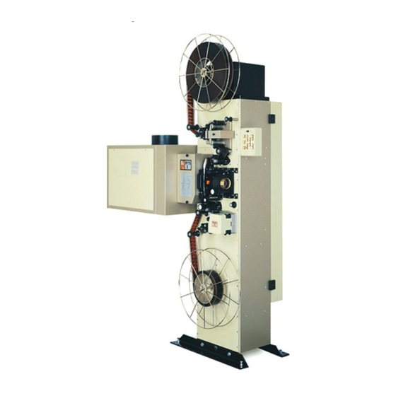
- Page 1 Operating Manual FP 75 E Double-Format Cinema Projector DIGITAL CINEMA FILM TECHNOLOGY STUDIO TECHNOLOGY CUSTOMIZED SOLUTIONS 360° DISPLAY SYSTEMS...
- Page 3 FP 75 E Preface Dear customer, this operating manual will help you get acquainted with the projector and to make use of its possible applications in accordance with the requirements. This operating manual includes important hints for a safe, proper, correct and economic operation.
- Page 4 This operating manual – even in extracts – may only be reprinted or otherwise copied with special, written permission from KINOTON GmbH. Editor responsible for the contents: KINOTON GmbH Editing and layout: Carmen Auer - KINOTON GmbH Hints / Own Notes...
-
Page 5: Table Of Contents
FP 75 E Contents Safety . . . . . . . . . . . . . . . . . . . . . . . . . . . . . . . . . . . . . . . . .1 Safety Notes . - Page 6 FP 75 E Transportation and Installation / Mounting . . . . . . . . . .9 Transportation ........9 Delivery or Equipment Variations .
- Page 7 FP 75 E Sound Devices ........25 3.3.1...
- Page 8 FP 75 E Operation and Troubleshooting . . . . . . . . . . . . . . . . . .37 Switch on and Start Projector / Stop and Switch off Projector 37 Threading for Projection Operation .
- Page 9 FP 75 E Cleaning / Maintenance / Repair . . . . . . . . . . . . . . . . . .49 General Hints .
- Page 10 FP 75 E Technical Data, Circuit Diagrams and Plans of Terminal Connections . . . . . . . . . . . . . . . . . .61 Technical Data .
-
Page 11: Safety
FP 75 E Safety 1 .1 Safety Notes 1 .1 .1 General Hints » Read this operating manual before operating the projector. » This operating manual is to be kept with the projector at all times. » For safe and trouble free operation of the projector a good working knowledge of basic safety regulations and the projector’s correct use is required. -
Page 12: Intended Purpose
Intended Purpose The projector is suitable to reproduce film images and sound. Any other or further use is not classified as an “intended purpose”. KINOTON cannot be held liable for any damage resulting from different or extended operation. As part of the “intended purpose” these tasks must be performed: »... -
Page 13: Special Hazard Points
FP 75 E NOTE This symbol indicates where notes, user tips and useful information can be found. They serve to help use the projector to its fullest. Always wear face protection when changing the xenon lamp. Always wear protection gloves when changing the xenon lamp. -
Page 14: Warning Risk Of Fire
FP 75 E 1 .3 .2 Warning Risk of Fire DANGER S Do not cover the projector or the lens with any material while the projector is in operation. S In the event of fire, use sand, CO , or dry powder fire extinguishers; never use water on an electrical fire. -
Page 15: Mechanical Danger
Therefore, avoid touching the coated lens surface. To remove dust on the lens, use a soft dry cloth (Cleaning set from Kinoton). Do not use a damp cloth, detergent solutions or thinner. Issue: 08/2012... -
Page 16: Service
Copyright Copyright of this manual remains in possession of KINOTON. This manual is intended for the user and its staff only. It contains regulations and operating notes that must not be copied, reproduced or otherwise transmitted, in whole or in part. -
Page 17: Protective Devices
FP 75 E 1 .6 Protective Devices All existing safety devices must be checked regularly 1 .6 .1 Main Switch In case of an emergency, you can switch off the projector using the main switch (under the projector door). Push the switch to position “0”. The red lamp in the switch turns off. -
Page 18: Water Flow Control
FP 75 E 1 .6 .4 Water Flow Control The flow control (arrow) monitors the continuous flow of the water cooling. If this flow interrupts the film break sequence will be triggered and the projector will be stopped. 1 .6 .5... -
Page 19: Transportation And Installation / Mounting
2 .2 Delivery or Equipment Variations » Projector FP 75 E - with opposed rotating double shutter - with electronic friction drives for film spools up to 2,000 m and reel platters up to 600 m - with roller set for using with a rewind system (option) »... -
Page 20: Installation
U Do not use unit parts as climbing aid. U The electrical connections have to be in accordance with local regulations and be installed professionally. U All installation should only be carried out by Kinoton service. 2 .3 .1 Place of Installation, Place of Operation »... -
Page 21: Important Hints For Installation
FP 75 E 2 .3 .2 Important Hints for Installation Projector Dimensions Issue: 08/2012... -
Page 22: Additional Installation Hints
FP 75 E 2 .3 .3 Additional Installation Hints ATTENTION U The 16 PE lines have to be high-flexible to derive the high-frequency ignition voltage. U Do not use the wires in the lamphouse cable to connect the additional dowser. -
Page 23: Projector Terminal Strips
FP 75 E 2 .3 .5 Projector Terminal Strips The whole terminal strip unit in the projector can be designed with 3 parts. The number of parts depend on the projector’s design: Terminal strip x1 - main terminal strip (white arrows) - is normally mounted. -
Page 24: Connecting The Water Cooling (Option)
The cooling fluid must have the following composition, to prevent a damage of the cooling coat around the intermittent sprocket motor: » 4 parts distilled and non-corrosive water » 1 part concentrate water additive from Kinoton NOTE You will find the description of the water cooling unit in the corresponding operating manual. -
Page 25: Function And Components
FP 75 E Function and Components The two-format FP 75 E projector is suitable to reproduce 35 mm and 70 mm film and sound formats. » Film is transported through the projector from top to bottom. » The intermittent sprocket is directly driven via the drive unit. -
Page 26: Components Overview
FP 75 E 3 .1 Components Overview Take-off friction with film spool (option) Á 70 mm magnetic sound device (option)  Operating panel à Lamphouse Ä Shutter housing Å Film gate with film pressure skate Æ Lens holder ... -
Page 27: Housing
FP 75 E 3 .1 .1 Housing Projection equipment, sound devices, frictions or/and set of guide rollers are mounted on the housing. Drives, motors, the whole electrical equipment and automation systems are mounted in projector housing. 3 .1 .2 Projection Components ... -
Page 28: Film Gate And Film Track
The four ceramics rollers guide the film laterally. » The FP 75 E projector can operate with 35 mm films and 70 mm films, therefore some components have to be changed with the film format. -
Page 29: The Dowser
FP 75 E 3 .2 .2 The Dowser The dowser (arrow) opens or closes the path of xenon light to the film gate. ATTENTION If the dowser does not close while the projector is stopped the film will burn. 3 .2 .3... -
Page 30: Lens Holder
FP 75 E 3 .2 .4 Lens Holder » The lens holder can be fed with a lens. » For inserting a lens loosen clamping screw (white arrow), put in the lens and then tighten the screw again. » Focusing can be done manually (black arrow) or optionally electronically. -
Page 31: Opposed Rotating Double Shutter
FP 75 E 3 .2 .5 Opposed Rotating Double Shutter The shutter is rotating as a opposed double shutter, which interrupts the projection light during film transportation one time and one time during each picture stands still. (48 interrupts/second with 24 frames/second) DANGER S Only remove or replace the shutter housing when the projector is off. -
Page 32: Combined Intermittent Sprocket
FP 75 E 3 .2 .6 Combined Intermittent Sprocket The intermittent sprocket is a very precise sprocket. It transports the film step by step through the film gate. The intermittent sprocket is driven directly via the intermittent sprocket motor. The projector is equipped with a combined intermittent sprocket for transporting 35 mm and 70 mm films. - Page 33 FP 75 E Combined feed sprocket 35 mm bottom sprocket Combined sprocket / 35 mm sprocket Á 70 mm pad shoe with handle / 35 mm pad shoe with handle  Pad shoe chuck knob à Film stripper Ä...
-
Page 34: Changing The Film Gate And Sprocket Parts (35 Mm / 70 Mm)
FP 75 E 3 .2 .8 Changing the Film Gate and Sprocket Parts (35 mm / 70 mm) The following parts can be changed corresponding to the film format: Pad shoes of the combined feed and bottom sprockets - Removing: Turn the chuck knob clockwise and pull out the pad shoe. -
Page 35: Sound Devices
FP 75 E 3 .3 Sound Devices 3 .3 .1 Reverse-Scan Sound Device (analog and optional DOLBY digital / upgradeable) Reverse-scan sound devices scan the sound track (analog and optional DOLBY digital) on the film via red LEDs. An only analog sound device is upgradeable with DOLBY digital. -
Page 36: Sound Tracks On The Films (35 Mm)
FP 75 E 3 .3 .1 .2 Sound Tracks on the Films (35 mm) Analog sound is printed as two wavy lines on the film. The height of the amplitude signifies loud- ness, frequency signifies pitch. The Dolby digital sound information (DOLBY SR·D) is encoded between the... -
Page 37: Drive Components
FP 75 E 3 .4 Drive Components NOTE Z In this chapter you will get an overview of the drive components, which are mounted in the projector. Z The projector door should only be opened by authorized service staff. Z All work on drives should be carried out by experts only. -
Page 38: Intermittent Sprocket Drive
NOTE Z Normally the set value is pre-adjusted and have not to change. If adjustments are necessary, they should be carried out by Kinoton service only. Z Operating the frictions, see chapter 4.3. 3 .4 .3 .2 Reel Shaft on Change Flange The reel shaft is mounted with a change- able flange (for 35 mm or 70 mm film). -
Page 39: Shutter Drive
FP 75 E 3 .4 .4 Shutter Drive Shutter Á Shutter drive  Shutter sensor board à Shutter drive motor Ä Shutter control adapter Å Shutter drive frequency inverter Æ Dowser » The shutter is driven via a toothed belt by the shutter motor. -
Page 40: Electronic Components
FP 75 E 3 .5 Electronic Components NOTE Z In this chapter you will get an overview of the electronic components, which are mounted in the projector. Z The projector door should only be opened by authorized service staff. Z All work on electronic parts should be carried out by experts only. -
Page 41: Components On The Basic Unit
Internal terminal strip Æ Main fuse 6.3 AT NOTE Adjusting the frequency inverter should only be carried out by Kinoton service or experts. 3 .5 .3 Shutter Drive Frequency Inverter The frequency inverter (arrow) which con- trols of the opposed rotating double shutter is placed inside of the projector’s top. -
Page 42: Led Board For Reverse-Scan Sound Device
FP 75 E 3 .5 .4 LED Board for Reverse-Scan Sound Device The LED board can be designed for analog and digital sound LED’s supply or for analog LED’s supply only. The LED board is powered via the projector with 24 V. -
Page 43: Operating Elements
FP 75 E Operating Elements 4 .1 Main Switch The main switch is positioned under the projector door. Main switch in position I: Current transfer is switched on. The switch lights up red. Main switch in position 0: Current transfer is switched off. -
Page 44: Friction Control
FP 75 E 4 .3 Friction Control NOTE Depending on your demands, the size of frictions can vary. Generally you can select between a large (e. g. 2000 m) and a small (e. g. 600 m) friction. Selection for take-up friction... -
Page 45: Remote Control Panels (Option)
FP 75 E 4 .4 Remote Control Panels (option) Projection Room Control Panel Auditorium Panels 4 .4 .1 Projection Room Control Panel House light ON Stage light ON Focusing + (option) House light HALF Stage light STOP Focusing - (option) -
Page 46: Auditorium Panel
FP 75 E 4 .4 .2 Auditorium Panel House light ON Stage light ON Focusing + (option) House light HALF Stage light STOP Focusing - (option) House light STOP Stage light OFF Frame UP Frame DOWN House light OFF AUTO... -
Page 47: Operation And Troubleshooting
FP 75 E Operation and Troubleshooting 5 .1 Switch on and Start Projector / Stop and Switch off Projector ATTENTION Do not stand too close on rotating film spools, because clothes, hair or other parts of your body can get winded up or trapped into the spools. -
Page 48: Threading For Projection Operation
FP 75 E 5 .2 Threading for Projection Operation For 35 mm film with sound • Put the full reel on the upper reel shaft or prepare the platter system. Take-off friction • - Open the sprocket pad shoe. - Thread the film in the combined feed sprocket (all perforations engage in the sprocket teeth). - Page 49 FP 75 E For 70 mm film with sound For 70 mm film without sound • Put the full reel on the upper reel shaft or prepare the platter system. • With magnetic sound: Thread the film through the magnetic sound device.
-
Page 50: Different Projection Speeds
FP 75 E • Thread the film into the film gate and close the film pressure skate. One whole frame must be centered vertically in front of the aperture opening. There is a small light inside the aperture to assist in centring. -
Page 51: Projection / Forward Running At 24 Fps Or 25 Fps
FP 75 E 5 .3 .2 Projection / Forward Running at 24 fps or 25 fps • To start press • Press “in” to select the speed of 25 frames/seconds (factory-set), press “out” to select the speed of 24 frames/seconds (factory-set). -
Page 52: Change-Over Operation
5 .4 Change-Over Operation • Push switch “in” on both FP 75 E projectors (provided the projectors are coupled with one another), to activate the change-over function. • The dowsers of the two projectors open or close alternatively. • The change-over projection can be started on any projector. -
Page 53: Troubleshooting
FP 25/30/38/50/75 E 5 .6 Troubleshooting 5 .6 .1 General Hints Even though we produce high quality, reliable equipment, there still can be problems due to incorrect operation, poor maintenance, incorrect procedures etc. This chapter has information about some common problems and about solving those problems. - Page 54 FP 25/30/38/50/75 E Error Cause Solution Picture moves - Skate pressure isn’t adjusted - Adjust vertically (jumps) correctly- - Skate height isn’t adjusted correctly - Adjust - Film print defective - Get new print [verify with test film] - Skate is worn - Change - Intermittent sprocket damaged - Change (service)
-
Page 55: Analog Sound
FP 25/30/38/50/75 E 5 .6 .4 Analog Sound Error Cause Solution No sound / some - sound processor failure - check plugs and power; call service channels missing - amplifier failure - check if sound track is threaded on the correct side - speaker failure - check / replace exciter lamp (standard... -
Page 56: Error Indication With Leds
FP 75 E 5 .7 Error Indication with LEDs 5 .7 .1 Interface Board Two red break LEDs (arrows) are mounted on the interface board. $The left LED (in the near of the projector door) labelled with Filmriss/break ext. illu- minates only if there is an external film break (e. -
Page 57: Main Board
FP 75 E 5 .7 .3 Main Board Red: intermittent sprocket drive is faulty Á Green: shutter motor runs synchronously  Green: shutter frequency is stored à Red: shutter rotates too slow Ä Red: shutter overload voltage is on Å... - Page 58 FP 75 E Issue: 08/2012...
-
Page 59: Cleaning / Maintenance / Repair
FP 75 E Cleaning / Maintenance / Repair 6 .1 General Hints ATTENTION U Any work on the electric supply wiring must be carried out by electricians. U Make sure that nobody starts the projector while you are working on it. -
Page 60: Maintenance
FP 75 E Every 2 weeks Component What is to do? Ceramics roller Remove the ceramics rollers and then remove the dirt in the holes by using air pressure. Clean the ceramics roller with a alcohol moisturized cloth. Every 3 months... -
Page 61: Repair
FP 75 E Annually Component What is to do? Sound reproducer Lubricate the pressure roller ball bearings with a drop of Cardan oil, type 8657. Do not use any other lubricant! Lubricate the sound drum shaft with 1 drop of Esso universal oil. -
Page 62: Changing A Constant Speed Sprocket
FP 75 E 6 .4 .2 Changing a Constant Speed Sprocket • Remove the pad shoe (black arrow) • Loosen the film stripper setscrews (2 or 4) and remove the film stripper (white arrow). • On the combined bottom sprocket remove the handwheel: - Remove the white cover. -
Page 63: Adjusting The Ir Reflex Film Break Sensor
FP 75 E 6 .4 .4 Adjusting the IR Reflex Film Break Sensor Position the sensor (arrow) in a way that it “looks” vertically towards the film surface. The sensor’s view must be perpendicular to the film. • To adjust the sensitivity of the sensor... -
Page 64: 6 .4 .5 .2 Checking And Adjusting The Film Pressure Skate Height
FP 75 E 6 .4 .5 .2 Checking and Adjusting the Film Pressure Skate Height $The projector is powered down, the film is threaded, the skate lifting is deactivated, the skate is closed. • Check the skate height for an available play by manually moving the skate up and down for about 0.3 mm - 0.5 mm. -
Page 65: 6 .4 .5 .3 Adjusting The Pressure Of The Skate
FP 75 E 6 .4 .5 .3 Adjusting the Pressure of the Skate • Thread and run a film. $The skate lifting is deactivated, the skate presses the film against the runner strips. • To adjust the skate pressure two adjusting screws /Á are available. -
Page 66: Adjusting The Lens Holder
FP 75 E $The more the skate and the runners wear the more the pressure has to be increased for best picture steadiness. $With the time the indicator  will move more and more to the left, in the direction of the film gate. -
Page 67: Parts And Wearing Parts
FP 75 E Parts and Wearing Parts 7 .1 Film Gate Parts (35 mm / 70 mm) Film Gate Fig . Order No . 1A / 2A 1000 463 17028 Film runner strips set for 70 mm film Film runner strips set for 35 mm film... - Page 68 FP 75 E Figure 1 Figure 3 Figure 2 Issue: 08/2012...
- Page 69 FP 75 E Figure 4 Figure 5 Figure 6 Issue: 08/2012...
-
Page 70: Film Spools
FP 75 E 7 .5 Film Spools Film Spools Order No . Film spool Ø 9 mm, 600 m film 0040 060 00050 Film spool Ø 12.7 mm, 1800 m film 0040 060 00765 Film spool Ø 12.7 mm, 2000 m film 0040 060 00770 7 .6... -
Page 71: Technical Data, Circuit Diagrams And Plans Of Terminal Connections
FP 75 E Technical Data, Circuit Diagrams and Plans of Terminal Connections 8 .1 Technical Data 8 .1 .1 Projector Name Cinema Projector Type FP 75 E Machine No. See data plate on housing. Connecting Data Power supply 120 V / 230 V... -
Page 72: Reverse-Scan Sound Device
FP 75 E 8 .1 .2 Reverse-Scan Sound Device Connecting Data Power supply 24 V Frequency 50 Hz / 60 Hz Power max. 6 VA Power and Operating Data Frequency response analog: 30 Hz - 16 kHz ± 1 dB digital: 20 Hz - 20 kHz ±... -
Page 73: Plans Of Terminal Connections
FP 75 E 8 .2 Plans of Terminal Connections 8 .2 .1 Plan of x1 Main Terminal Connections Source (projector inside) Color No . Color Projector Outside intern extern protect. conduct., ground (40) PE gn/ye mains connection mains-phase (60) L1... -
Page 74: Plan Of X2 Terminal Strip For Projector Functions (Optional)
FP 75 E 8 .2 .2 Plan of x2 Terminal Strip for Projector Functions (optional) No . Connection Colour Interface: EMK 1 Connection: (source) Terminal / No . No . (bk) Relay + 24 V - 24 V Start FOR-... -
Page 75: Plan Of X3 Terminal Strip For Auditorium Functions (Option)
FP 75 E 8 .2 .3 Plan of x3 Terminal Strip for Auditorium Functions (option) No . Connection / Function with EMK 1: No . (bk) Curtain COM Curtain OPEN Curtain CLOSE House light COM House light ON House light HALF... -
Page 76: 35 Mm Sound Output On 8-Pole Terminal Strip
FP 75 E 8 .2 .5 35 mm Sound Output on 8-pole Terminal Strip Solar cell connection Solar cell connection Solar cell connection Shield Sound output left - (yellow) Sound output left + (brown) Sound output right - (white) Sound output right +... -
Page 77: Block And Circuit Diagrams
FP 75 E 8 .3 Block and Circuit Diagrams 8 .3 .1 Block Diagram (Components Overview) Issue: 08/2012... -
Page 78: Main Board Components Overview
FP 75 E 8 .3 .2 Main Board Components Overview I n t e r f a c e O u t p u t s O u t p u t s I n t e r f a c e... -
Page 79: Lamphouse For 230 V Mains Connection
FP 75 E 8 .3 .3 Lamphouse for 230 V Mains Connection M 1 L a m p F a n M 2 F a n M o t o r H o u r C o u n t e r... -
Page 80: Lamphouse For 120 V Mains Connection
FP 75 E 8 .3 .4 Lamphouse for 120 V Mains Connection L a m p f a n F a n m o t o r H o u r c o u n t e r S K 1... - Page 81 EC Declaration of Conformity Kinoton GmbH Company name Address: Industriestr. 20a, D-82110 Germering Machine designation: Cinema Projector FP 75 E Machine type: Maschine serial number: V0150 Relevant EC stipulations: Machine regulation 2006/42/EG Low Voltage regulation 73/23/EWG EMC regulation 2004/108/EG Standards:...
Need help?
Do you have a question about the FP 75 E and is the answer not in the manual?
Questions and answers