Advertisement
Quick Links
Installation instructions
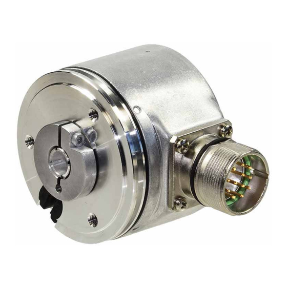
Incremental Hollow Shaft Encoder
RI 58-D, RI 58TD
Item No. 2 531 069, Edition: 3 160604 Ste1
Introduction
These installation instructions are provided for the connection and starting procedure of
your shaft encoder. The shaft encoder is available in two versions:
Standard version (RI 58-D) or High Temperature version (RI 58TD)
and each in the mounting versions:
• F* = Blind shaft with front clamping ring
• E* = Blind shaft with screw connection
• D* = through shaft with front clamping ring
• H* = through shaft with rear clamping ring
* F, E, D, H = code for mounting versions (see Identification code)
Safety and Operating Instructions
• The incremental shaft encoders of the type RI 58-D / RI 58TD model series are quality
products manufactured in accordance with established electrical engineering standards.
The units have been delivered from the factory in perfect conformance to safety regulations.
To maintain this condition and to ensure trouble-free operation, please observe the
technical specifications of this document.
• Installation and mounting may only be performed by an electrotechnical expert!
• The units may only be operated within the limits specified by the technical data.
• Maximum operating voltages must not be exceeded!
The units are designed complying with VDE 0160, protection class III.
To prevent dangerous structure-borne currents, the equipment has to be run on safety
extra-low voltage (SELV) and must be in an area of equipotential bonding.
• Application: Industrial processes and control systems.
Overvoltage at the connecting terminals must be limited to the values within overvolta-
ge category II.
• The high-quality EMC-specifications are only valid together with standard-type cables
and plugs. When using screened cables, the screen must broadly be connected with
ground on both ends. Likewise, the voltage-supply cables should entirely be screened.
If this is not possible you will have to take appropriate filtering measures.
• Installation environment and wiring are influential on the encoder's EMC: Thus the
installer must secure EMC of the whole facility (device).
• Transient peaks on the power supply leads are to be limited by the pre-connected power
unit to a maximum of 1000 V.
• In electrostaticly threatened areas please take care for neat ESD-protection of plug and
connecting cable during installation work.
• For use in class II circuits only
Connection diagram
Output
Colour (TPE) Colour (PVC) RS 422 (T)
+ Sense
brown
white
Channel A
green
white/brown
Channel A
grey
green
Channel B
pink
green/brown
Channel B
red
yellow
Channel N
black
yellow/brown Channel N
2)
violet (white)
yellow/black
Sense GND
blue
yellow/red
Sense V
brown/green red
5 V DC
white/green black
GND
1)
1)
1)
Screen
Screen
Screen
1)
connected to encoder housing
2)
white for Sense (T)
Identification code (see identification plate)
D direct hollow shaft
Supply voltage
A 5 VDC
Version
E 10 ... 30 VDC
– Standard
T High Temperature
/
R I 5 8
D
Number of
Output
pulses
K push-pull
1 ... 5,000
R RS 422 + Alarm
Protection class
T RS 422 + Sense
I push-pull complementary
housing/ball bearing
D push-pull 5 V, 30 mA
3 IP 64/64
4 IP 65/64
*
Special types are additionally marked by an ordering code -S. In this case customer specifications are to be
applied. If you don't know these please call us for the specifications, indicating the encoder ordering code.
Page 1/2
RS 422 (R)
Push-pull
+ Alarm
(K, D)
plementary (I)
Channel A
Channel A
Channel A
Channel A
Channel A
Channel B
Channel B
Channel B
Channel B
Channel B
Channel N
Channel N
Channel N
Channel N
Channel N
Alarm
Alarm
Alarm
Sense V
Sense V
CC
CC
5/10...30 V DC 5/10...30 V DC 10...30 V DC
GND
GND
GND
1)
1)
Screen
Screen
Screen
Mounting
Shaft diameter
Synchro flange with
2 10 mm
F clamping blind shaft
7 12 mm
E screw blind shaft
9 14 mm
D front clamping shaft
D 15 mm
H rear clamping shaft
·
Type of connection
B cable PVC radial
F cable TPE radial
D CONIN flange box radial, right-turning
H CONIN flange box radial, left-turning
Mechanical Data
Mounting
Hollow shaft diameter
Speed
Torque
Moment of inertia
Protection class housing/ball bearing
Operating temperature
Storage temperature
Vibration performance (IEC 68-2-6) 10 g = 100 m/s
Shock resistance (IEC 68-2-27) 100 g = 1000 m/s
Type of connection
Housing
Weight
1)
no standing water allowed at the shaft entrance or at the ball bearing
2)
when mounted
Electrical data
General design
Screening
Noise emission
Noise immunity
Power consumption
Supply voltage U
1)
Output circuit
Code letter
Output load [mA]
Output level [V]
Push-pull com-
Pulse rise time [ns]
Max. pulse frequency [kHz]
Pole protection of U
Short circuit proof
Pulse duty factor
Pulse width error
Phase shift
Pulse shape
CC
Alarm output
1)
PP = Push-pull; PP compl .= Push-pull complementary; RS422 = Line driver
1)
Pinout of flange box,
Pin
RS 422 (T)
1
Channel B
2
Sense V
CC
3
Channel N
4
Channel N
5
Channel A
*
6
Channel A
7
N.C.
8
Channel B
9
N.C.*
10
GND
11
Sense GND
12
5 V DC
* Screen for cable with CONIN-plug
Hengstler GmbH
Postfach 11 51
D-78554 Aldingen
synchro flange with clamped shaft or blind shaft
10/12/14/15 mm; required dim. of mounting shaft:
∅ 10 mm, tolerance g8 (-0.005 ... -0.027 mm)
∅ 12/14/15 mm, tolerance g8 (-0.006 ... -0.033 mm)
E, F: max. 6000 RPM; D, H: max. 4000 RPM
E, F: ≤ 1 Ncm (IP 64); D, H: ≤ 2 Ncm (IP 64)
2
F: approx. 35 gcm
; E: approx. 20 gcm
1)
E, F: IP 65/64; D, H: IP 64/64
RI 58-D: –10 ... +70 °C; RI 58TD: –25 ... +100 °C
–25 ... +85 °C
2
(10 ... 2000 Hz)
2
(6 ms)
cable radial, connector radial
aluminium
E, F: 170 g approx.; D, H: 190 g approx.
as per DIN VDE 0160, protection class III,
contamination level 2, overvoltage class II
connected to housing
as per EN 50081-2 (edition 1993)
as per EN 50082-2 (edition 1995)
40 mA (5 V DC), 30 mA (24 V DC), 60 mA (10 V DC)
±10%
5 V DC (SELV)
B
PP
PP
RS422
K
D
R, T
±10 ±30
±30
≥2.5 ≥2.5
≥2.5
High
≤0.5 ≤0.5
≤0.5
Low
250 100
100
300 300
300
yes
no
no
B
yes
1 channel 1 channel yes
1 : 1
± 25° electrical
90° (Channel A to B is at least 0.45 µs at 300 kHz)
rectangular
Open Collector, NPN (5 mA, 24 V max. with U
5 mA, 32 V max. with U
CONIN 12 poles
RS 422 (R)
Push-pull (K, D)
Channel B
N.C.
Sense V
N.C.
CC
Channel N
Channel N
Channel N
N.C.
Channel A
Channel A
Channel A
N.C.
Alarm
Alarm
Channel B
Channel B
N.C.*
N.C.*
GND
GND
N.C.
N.C.
5/10 ... 30 V DC 5/10 ... 30 V DC
Tel. 07424 – 890
Fax 07424 – 89470
2
2
; D, H: 60 gcm
2)
10 ... 30 V DC (SELV)
PP
PP compl. RS422
K
I
R
±30
±30
±30
≥2.5
U
-3 U
-3
B
B
≤2
≤2
≤0.5
2000 2000
100
200
200
300
yes
yes
yes
yes
yes
=5 VDC;
B
=10...30 VDC)
B
Push-pull complementary(I)
Channel B
Sense V
CC
Channel N
Channel N
Channel A
Channel A
Alarm
Channel B
N.C.*
GND
N.C.
10 ... 30 V DC
Advertisement

Related Manuals for Hengstler RI 58-D


Summary of Contents for Hengstler RI 58-D
-
Page 1: Safety And Operating Instructions
Safety and Operating Instructions Operating temperature RI 58-D: –10 … +70 °C; RI 58TD: –25 … +100 °C • The incremental shaft encoders of the type RI 58-D / RI 58TD model series are quality Storage temperature –25 … +85 °C products manufactured in accordance with established electrical engineering standards. -
Page 2: Mechanical Installation
Installation instructions Incremental Hollow Shaft Encoder RI 58-D, RI 58TD Page 2/2 Checking the clamping device (D, F, and H versions) Mechanical installation The clamping device of versions D, F, and H contains a clamping ring with a General information hexagon-socket screw.
Need help?
Do you have a question about the RI 58-D and is the answer not in the manual?
Questions and answers