Chapters
Table of Contents

Related Manuals for Hengstler AX73


Summary of Contents for Hengstler AX73
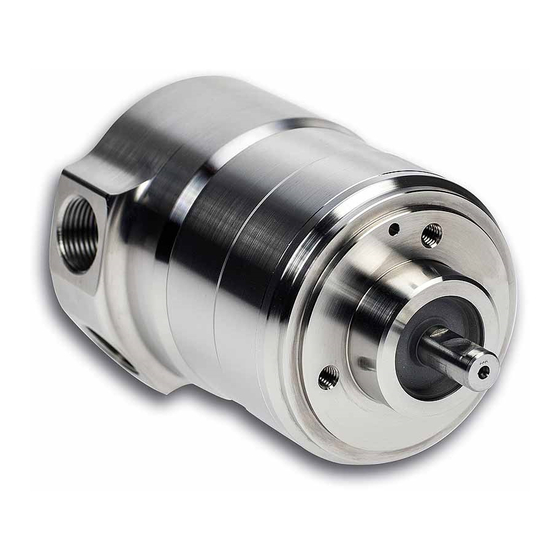
- Page 1 Installationsanleitung Installation instructions Absolut - Drehgeber Absolute Shaft Encoder AX73 IP67 mit BiSS / SSI with BiSS / SSI Item number: 2-539-198, Version: 3 241016TK 1 of 20...
- Page 2 © by HENGSTLER Für diese Dokumentation beansprucht die Firma HENGSTLER Urheberrechtschutz. Diese Dokumentation darf ohne vorherige schriftliche Zustimmung der Firma HENGSTLER, weder ab- geändert, erweitert oder vervielfältigt, noch an Dritte weitergegeben werden. ® ACURO ist eine eingetragene Marke von Hengstler.
-
Page 3: Table Of Contents
Installationsanleitung Absolut - Drehgeber AX73 mit BiSS / SSI Inhaltsverzeichnis 1. Vorwort ..........................4 2. Allgemeines ........................4 ................2.1. Symbolerklärungen / Warnhinweise 3. Sicherheits- und Betriebshinweise .................. 5 ..................3.1. Komponenten des Drehgebers ..............3.2. Demontage / Montage der Anschlusshaube ........ -
Page 4: Vorwort
Dieser Drehgeber ist Ex - geprüft und zugelassen nach ATEX und IECEx. Die EG- Baumuster- prüfbescheinigung senden wir Ihnen auf Anforderung gerne zu. Informationen zur Datenschnittstelle finden Sie im technischen Handbuch: Technical Manual SSI/BISS (siehe www.hengstler.de) Weitere Informationen erhalten Sie auf Anfrage. Voraussetzung für sicheres Arbeiten ist die Einhaltung aller angegebenen Sicherheitshinweise und Handlungsanweisungen. -
Page 5: Sicherheits- Und Betriebshinweise
3. Sicherheits- und Betriebshinweise Die Absolut - Drehgeber der Modellreihe AX73 sind nach den anerkannten Regeln der Elektrotechnik hergestellte Qualitätsprodukte. Die Geräte haben das Herstellerwerk in sicherheitstechnisch einwandfreiem Zustand verlassen. Um diesen Zustand zu erhalten und um einen störungsfreien Betrieb sicherzustellen, sind die technischen Spezifikationen in dieser Dokumentation zu berücksichtigen. -
Page 6: Komponenten Des Drehgebers
Zum Schutz ist eine externe Sicherung zu verwenden (siehe Elektrische Daten). Anwendungsbereich: Industrielle Prozesse und Steuerungen. Überspannungen an den Anschlussklemmen müssen auf Werte der Überspannungskategorie II be- grenzt werden. Vermeiden Sie die Einwirkung von Schocks auf das Gehäuse - vor allem auf die Geberwelle - sowie axiale und radiale Überbelastung der Geberwelle. -
Page 7: Verwendung Von Kabel, Verschlussstopfen Und Kabeleinführung
Warnung! Es dürfen nur die mitgelieferten Befestigungsschrauben mit montiertem Sicherungsring verwendet werden (Sonderverschlüsse nach EN 60079-0:2009). Anschlusshaube muss umlaufend ohne Spalt am Drehgeber anliegen. Warnung! Eine Verwendung des Drehgebers ist nur mit verklebten Befestigungsschrauben zulässig! Inbetriebnahme nur mit montierter Anschlusshaube. 3.3. -
Page 8: Anzugsdrehmomente Der Anschlusshaube
Anforderungen der geltenden Normen und Vorschriften entsprechend festzulegen. Befestigungsschraube für Anschlusshaube Erdungsschraube Kabelverschraubung 3.5 EX - Klassifizierung Die Hengstler EX – Drehgeber sind klassifiziert nach: EG- Baumusterprüfbescheinigung: ITS14ATEX17991X IECEx Zertifikat: IECEx ITS 14.0062X Gas: Ex II 2 G Ex d IIC T4 Gb Staub: Ex II 2 D Ex tb IIIC T130 Db Umgebungstemperaturbereich: -40°C ≤... -
Page 9: Mechanische Daten
4. Mechanische Daten / Umgebungsbedingungen Gehäusedurchmesser 73,5 / 76mm Wellendurchmesser 10mm Befestigung Klemmflansch, 3x Bohrung M6 Wellenbelastung max. radial 100N, axial 40N Drehzahl max. 3000 U/min Nenndrehzahl 1500 U/min Anlaufdrehmoment typ. ≤ 4 Ncm Trägheitsmoment ca. 30 gcm Schutzart (EN 60529/ A1:2000-02) Gehäuse IP66/IP67, Kugellager IP67 Umgebungstemperaturbereich -40°C …... -
Page 10: Anschlussbelegung
Elektrische Daten (Fortsetzung) Ausgangstreiber RS422 Kabellänge max. 400m bei Einhaltung der Sicherheits- und Betriebshinweise Die maximale Taktfrequenz ist abhängig von der Leitungslänge und der Kabelqualität. Verwenden Sie ein geschirmtes Kabel mit paarweise verdrillten Leitungspaaren für Takt u. Takt\, Data u. Data\ sowie U und GND Taktfrequenz: <... -
Page 11: Bestellschlüssel
8. Bestellschlüssel (siehe Typenschild) Auflösung Versorgung Flansch, Schutzart, Welle Schnittstelle Anschluss K.72 AX73 AX73 0010 10 Bit ST E DC 10 - 30 V K.72 Klemmflansch, IP67, SG SSI Gray 2 2x M20x1,5 Innengewinde, 0012 12 Bit ST 10 mm SB SSI Binär... - Page 12 Installation Instructions Absolute - Encoder AX73 with BiSS / SSI Table of Contents 1. Introduction ........................13 2. General ..........................13 ................. 2.1. Explanation of symbols / Warnings 3. Safety and Operating Instructions ................. 14 .................... 3.1. Components of the Encoder ..............
-
Page 13: Introduction
EC-TYPE-Examination Certificate. For information concerning interfacing please refer to the Technical Manual SSI/BISS. (See www.hengstler.de) You will get further information on request. Compliance with all of the security information and procedural instructions is essential to en- sure work safety. -
Page 14: Safety And Operating Instructions
3. Safety and Operating Instructions The absolute shaft encoder of type AX73 model series are quality products manufactured in accord- ance with established electrical engineering standards. The units have been delivered from the factory in perfect conformance to safety regulations. To main- tain this condition and to ensure trouble - free operation, please observe the technical specifications of this document. -
Page 15: Components Of The Encoder
Overvoltage at the connection terminals must be limited to overvoltage - class - II values. Please avoid shocks to the housing - especially to the encoder shaft - and axial or radial overload to the encoder shaft. Maximum accuracy and durability of our shaft encoders are only guaranteed when using suitable couplings. -
Page 16: Use Of Cables, Plugs And Cable Entry
Warning! The O-ring between encoder and terminal box must not be damaged. Tighten up both screws within the curing of the adhesive to a torque of 4 Nm. Warning! Use only the supplied fixing screws with a pre-mounted securing ring (specific screw caps according to EN 60079-0:2009). -
Page 17: Tightening Torques Of The Terminal Box
Fixing screw for terminal box Grounding screw Cable gland 3.5. Explosion Protection Classification Hengstler explosion - proof shaft encoders are classified according to EC-TYPE-Examination Certificate: ITS14ATEX17991X IECEx Certificate: IECEx ITS 14.0062X Gas: Ex II 2 G Ex d IIC T4 Gb... -
Page 18: Mechanical Data
4. Mechanical data Housing diameter 73,5 / 76mm Shaft diameter 10mm Mounting Clamping flange, bores 3xM6 Shaft load max. radial 100N, axial 40N Speed max. 3000 rpm Nominal speed 1500 rpm Torque ≤ 4 Ncm Moment of inertia 30 gcm approx. -
Page 19: Connection Diagram
Electrical data (continued) Drives RS422 Cable length max 400 m With compliance with the safety and operating instructions The maximum clock frequency depends on cable length and cable quality. Please use a screened cable with twisted cable pairs for clock and clock\; data and data\ as well as Ub and GND. Clock frequency: <... -
Page 20: Identification Code
8. Identification Code (see identification plate) Supply Type Resolution Flange, Shaft, Protection Interface Connection Voltage AX73 K.72 AX73 0010 10 Bit ST E DC 10 - 30 V K.72 Clamping flange, IP67 SG SSI Gray 2 2x M20x1,5 screw thread,...
Need help?
Do you have a question about the AX73 and is the answer not in the manual?
Questions and answers