Table of Contents
Advertisement
Quick Links
Advertisement
Table of Contents

Related Manuals for Unical BAHR’UNO


Summary of Contents for Unical BAHR’UNO
- Page 1 BAHR’UNO INSTRUCTIONS ON INSTALLATION, USE AND MAINTENANCE...
- Page 2 DATA PLATE Modello Pressione max. ammiss. PS (bar) Model Max. Design Pressure Numero di Fabbrica Pressione max. di esercizio (bar) Serial Number Max. Working Pressure Anno di Fabbricazione Temperatura max. ammis. TSmax (°C) Manufacturing Year Max. Allowable Temperature Potenza Nominale (kW) Temperatura max.
-
Page 3: Table Of Contents
1 GENERAL INFORMATION ....................................4 1.1 General warnings ......................................4 1.2 Symbols used in the manual ..................................5 1.3 Safety warnings ......................................5 2 TECHNICAL FEATURES AND DIMENSIONS ..............................7 2.1 General description of the range ..................................-7 2.2 Description of components ................................... 8 2.3 General features ...................................... -
Page 4: General Information
GENERAL INFORMATION 1.1- GENERAL WARNINGS This document is the Technical Manual for installation, use and ATTENTION! maintenance of BAHR'UNO type low pressure flame blowing Incorrect installation, inadequate use and steam generators. maintenance of the appliance can cause damage to persons or property, for which BAHR’UNO steam generators (with the exception of those fitted the MANUFACTURER is not liable. -
Page 5: Symbols Used In The Manual
The generator is excluded from commissioning the territory, as defined in art. 6 of Italian Ministerial Decree of 1 verification as it meets art. 5, paragraph d) of the December 2004 No. 329 Italian Ministerial Decree. 1 December 2004 No. 329; However, the user MUST COMMUNICATE - The user has the obligation to submit the steam generator to COMMISSIONING TO THE LOCAL COMPE- the periodic inspections of law provided for by the Italian Min- TENT AUTHORITIES AS SET OUT IN ART. - Page 6 In the event of dam- parts with technical safety function. Replace age, do not change the created state, before the authorised in- the faulty parts with original Unical spare spection body has carried out a check, unless this constitutes a parts only.
-
Page 7: Technical Features And Dimensions
The series of high pressure steam generators, with smoke IMC control board composed of: pipes, with flame blowing furnace, high performing BAHR’UNO - IMC control panel including wiring (pressure gauges, Unical STEAMER is designed for a maximum allowable pres- probes, burner power), sure PS = 1,0 bar. - no.4 level probes (min, max, safety), The range includes no. -
Page 8: Description Of Components
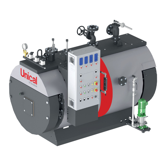
2.2. - DESCRIPTION OF THE COMPONENTS 1 Control board 12 Steam intake valve 2 Level indicator 13 Manhole 3 Capacity probe unit (optional - only with IML) 14 Probe holder flange 4 Salinity control unit (TDS) 15 Probe holder flange 5 Supply pump(s) unit 16 Pressure gauge 6 Flow regulation pneumatic valve (optional) 17 Pressure switch 7 Thermometer (optional) -
Page 9: General Features
2.3 - GENERAL FEATURES The flame blowing generator is composed by cylindrical hearth It is equipped with self-cleaning flame-warning light, suitably with wet end in which the flame develops and where the reversal positioned to control the correctness of combustion in opera- of the combustion products occurs. tion; on the same is bolted the burner coupling plate, supplied The fumes, therefore, enter the tube bundle at the front tube blind, can be prepared for the type of burner indicated by the plate and are conveyed towards the rear smoke chamber from customer. -
Page 10: Dimensions
2.4 - DIMENSIONS BAHR’UNO OR Steam inlet Safety valve drain Water supply Boiler drain Weightin Weight BAHR’UNO Ø oper. empty Model 1030 1340 1100 DN 50 DN 50 1” 1/2” 1560 1865 1485 1220 1030 1340 1100 DN 50 DN 50 1”... - Page 11 BAHR’UNO STD - EC - HP - HPEC - HPO - HPOEC Steam inlet Safety valve drain Water supply Boiler drain Weight Weight BAHR’UNO Ø in oper. empty T T4 Model 1100 1420 1560 1800 1485 1100 1220 DN 50 DN 32 1”...
-
Page 12: Operation Data
2.5 - DATI DI FUNZIONAMENTO... -
Page 16: Installation Instructions
INSTRUCTIONS FOR INSTALLATION 3.1 - GENERAL WARNINGS Before connecting the boiler, have professionally qualified personnel: a) Thoroughly wash all the system piping to ATTENTION! remove any residues or impurities which The generator must be destined only to the could jeopardise the proper operation of use for which it has been expressly declared. -
Page 17: Supply Conditions
3.3 - TERMS OF SUPPLY The BAHR’UNO generators are supplied in single-block. NOTE: Normally, the generators are supplied fully Upon receipt, after having removed the packaging assembled. In particular cases, to avoid dam- make sure the content is intact. age during transportation or handling, some Carry out a general inspection to verify the absence units are supplied unassembled. -
Page 18: Positioning In Boiler Room
3.5 - POSITIONING IN THE BOILER ROOM The steam generator must be installed in a place that complies b) On the two sides of the generator: 0.80 m, reduced to with the safety requirements in force in the country of destina- 0.60 m if the generator is adjacent to a wall or to another tion, with adequately dimensioned ventilation openings. -
Page 19: Water Features
3.6 - WATER FEATURES The generator must be fed with water of It is appropriate to recover as much condensate water in the quality complying with the requirements set supply tank as possible. out in this paragraph. It must also be ensured that the feed water The condensate water must eventually be treated so as to meet the and the system water cannot be polluted requirements indicated for the generator feed water (as per table 1). - Page 20 Table 2 OPERATING WATER FOR STEAM GENERATORS Parameters Unit Conductivity of the feed water Conductivity of the > 30 mS/cm feed water < 30 mS/cm Operating pressure 0.5 - 20 > 20 > 0.5 Appearance Clear, free from solid suspensions without persistent foam Conductivity mS/cm <...
- Page 21 FREQUENCY OF THE ANALYSES WATER PARAMETERS CHECK The frequency of the analyses depends on the use of the (DAILY) generator and the quality of the water used; however, it is advisable to check the pH value, the total hardness and alkalinity System Manager / Operator Responsibility of the feed water and operating water every two days.
-
Page 22: Hydraulic Connections
3.7 - HYDRAULIC CONNECTIONS ATTENTION! Before connecting the boiler to the system, thoroughly wash the pipes with a strong jet of steam, in order to eliminate metallic residue from processing and welding, oil and grease which could be present and which, reaching the boiler, could alter its functioning. -
Page 23: Gas Connection
3.9 - GAS CONNECTION Check the internal and external seal of the fuel supply system. Gas connection If using gas, the connections must be per- fectly sealed. Danger! The gas connection must be carried out only Check that the fuel supply system is by a qualified installer who must respect and equipped with safety and control devices apply that foreseen by relevant laws in force... -
Page 24: Connection To The Flue
3.11 - CONNECTION TO THE FLUE The correct combination burner / boiler / chimney enables a significant reduction of consumption and an optimal fuelling with low polluting emissions. The FLUE (CHIMNEY) must be resistant to heat and conden- sation, thermally insulated, with hermetic seal, without restric- tions or occlusions, as vertical as possible and dimensioned according to the provisions of the standards in force The CONNECTION BETWEEN BOILER AND CHIMNEY must... -
Page 25: Burner Assembly
In addition, the generator’s flame sight glass must be Note: for operation with oil burners, consult the connected to the burner’s air inlet. Unical AG Technical Service beforehand If the cooling tube is not connected to the ATTENTION! flame sight glass, it could cause the glass The BAHR'UNO HPO/HPO EC generators can to blacken and break. -
Page 26: Furnace Door: Adjustment, Opening, Closing
ATTENTION! f. In the presence of adapter flange for door/burner cou- The seat of the burner blast tube must be pling, make sure the flue gas seal gaskets are mounted as precise as possible to avoid flashbacks on both coupling surfaces. or heat returns that would make the burner connection plate red hot. -
Page 27: Electrical Connections
3.14 - ELECTRICAL CONNECTIONS Connection to electric power supply General warnings The generators are equipped with an electrical panel completely assembled and connected to the various accessories on the The electrical system must be made and generator itself. checked by professionally qualified person- nel in accordance with the law, who certifies To connect the control panel please refer to the the suitability:... -
Page 28: Control Panels
3.15 - CONTROL PANELS IML (Industrial Multi Logic) GENERAL FEATURES case to case. The IML control manages all of the adjustment devices and the The standard supply includes that it is made up from: interface with the safety devices that are type-approved in ac- - metal box cordance with the provisions of the regulations included in the - electro-mechanical power components... - Page 29 PANEL KEY 12 Alarm siren Alarm luminous buttons LC3050 LC3050 LC3050 TDS SAFE - Push to Reset: Salinity control unit alarm ALARM ALARM ALARM warning light (optional) HWL SAFE - Push to Reset: High level probe alarm warn- ing light (optional) LWL SAFE 2 - Push to Reset: Low level probe 2 alarm TDS SAFE HWL SAFE...
- Page 30 BASIC PANEL KEY 12 Alarm siren Alarm luminous buttons LC3050 LC3050 LC3050 LWL SAFE 1 - Push to Reset: Low level probe 1 alarm ALARM ALARM ALARM warning light LWL SAFE 2 - Push to Reset: Low level probe 2 alarm warning light HWL SAFE - Push to Reset: High level probe alarm warn- LWL SAFE1...
-
Page 31: Commissioning
3.16 - FIRST IGNITION ATTENTION! Preliminary checks ANY INTERVENTION ON THE APPLIANCE MUST BE DONE BY PERSON ENABLED TO The installation, operation and maintenance RUN SYSTEMS, PURSUANT TO ITALIAN must be carried out in compliance with the LEGISLATIVE DECREE 1 MARCH 1974: regulations in force, following the instruc- "RULES TO ENABLE TO RUN STEAM GEN- tions described in this manual;... - Page 32 Start-up Verify that the selector switch ENABLE BURNER OPERATION BMODE ON BASIC IMC/IML / OFF is in position “OFF” (BASIC panel) or “0” (IMC / IML panel), so that the burner does not start when the panel is powered. B MODE B MODE MAN-0-AUTO OFF ON...
- Page 33 P1 MODE P2 MODE Start the feed pump by MANactivation from the panel, in order to force filling MAN 0 AUT MAN 0 AUT (the warning light P1 (2) MODE RUN lights-up). HWL SAFE Once the MAX level is reached, check the intervention of the HwL high level PUSH to RESET safety probe by the switching on of the alarm warning light HWL SAFE - PUSH to RESET on the panel.
- Page 34 P1 MODE P2 MODE Turn off the pump by placing the selector in position 0 . MAN 0 AUT MAN 0 AUT LWL SAFE 1 LWL SAFE 2 Force generator emptying below the pump SET / ON level in manual mode to PUSH to RESET PUSH to RESET verify intervention of LWL1 and LWL2 low level safety probes. Check that the alarm warning light LWL SAFE 1 - PUSH to RESET (LWL SAFE 2 - PUSH to RESET) switches on.
- Page 35 ATTENTION! POTENTIALLY DANGEROUS OPERATION. SINCE IT IS NECESSARY TO EXCLUDE PRESSURE CONTROL AUTOMATISMS, THE FOLLOWING OPERA- TIONS MUST BE CARRIED OUT BY UNICAL PERSON- NEL AND / OR AUTHORISED AND TRAINED FOR THE PURPOSE. Close the steam main intake valve...
- Page 36 Once the pressure value of 0,3-0,4 bar is achieved, manually act on the safe- ty valve to check that the lever is free to move, the shutter is not stuck and it allows the venting of air. Tighten the closing nuts of the MANHOLE door which may have been loos- ened by the pressure.
- Page 37 Restart the burner and check its stop automatically checking the pressure of intervention on the gauge. Burner restart is automatic when the pressure inside the generator has dropped by the corresponding value of the set differential. AT THIS POINT THE GENERATOR IS READY FOR OPERATION GRADUALLY OPEN THE PRESSURE INTAKE VALVE IN OR- DER TO GRADUALLY HEAT THE PIPES Recommendations for using the generator on the first day of operation.
-
Page 38: Subsequent Start-Ups And Operation
3.17 - SUBSEQUENT START-UPS - Check that all valves and all shut-off valves are in a position suitable for operation; AND OPERATION - check the correct position of the cocks of the pressure gauge and of the level indicator; NOTE - check that the key selector for the operation of the electric If using the generator in manual mode, per- pump is set to "'AUTomatic";... -
Page 39: Instructions For Stopping The Generator
3.18 - INSTRUCTIONS FOR STOPPING THE GENERATOR - Purge, with rapid openings, the generator and the level indica- NOTE tor (operation to be carried out daily even in case of continu- If the shutdown period is such to bring the ous operation of the generator);... -
Page 40: Instructions For Decommissioning And Storage
3.20 - INSTRUCTIONS FOR SHUTDOWN AND STORAGE Dry conservation To avoid corrosion by inactivity in the absence of pressure, the smoke side and water side surfaces of the boiler must be treated according to the duration of the functioning interruption. Warning There is a distinction between wet conservation (for which the This method must be used in the event of pro-... -
Page 41: Inspections And Maintenance
INSPECTION AND MAINTENANCE 4.1 - GENERAL RULES FOR RUNNING - It is forbidden because dangerous, even partially obstruct the air vents for the cor- STEAM GENERATORS rect ventilation of the boiler room. The yield and duration of a steam generator - It is absolutely forbidden to touch the hot depend not only on a proper installation but parts of the generator which are heated... -
Page 42: Maintenance Instructions
Instructions for routine maintenance WATER SIDE: - disassembly of level probes; Carry out the following checks: - opening of manhole; - check the mechanical and electrical efficiency of the adjust- ment and safety devices; - internal inspection to ascertain the presence of deposits or signs of corrosion;... -
Page 43: Operating Anomalies
Malfunctions EVENT PROBABLE CAUSE POSSIBLE SOLUTION Safety valve intervention Exceeding of maximum calibration pressure Check the intervention threshold of the pressure of the valve switches Loss of calibration of the safety valve Check the calibration value of the valve Leakage of the safety valve Deposits of dirt around the shutter seat Cleaning of the seat by quick and repeated drives of the manual opening lever of the valve... - Page 44 EVENT PROBABLE CAUSE POSSIBLE SOLUTION Faulty burner adjustment Dirt Clean according to instructions provided in the burn- er manual Insufficient tightness of the smoke circuit Check the state of the gaskets, closure of the doors, burner plate set up and connection to the chimney fitting Irregularity of the flow of fuel Check the burner and power supply line according to the instructions given in the specific burner manual.
-
Page 45: Residual Risks From Risks Analysis Pursuant To The European Directive 97/23/Ec - Ped
Residual risks from Risks Analysis pursuant to the European Directive 97/23/EC - PED EVENT CAUSE 21 GASKETS Severity Event: D No tightness of the gaskets on water and steam sids EFFECT - CONSEQUENCE - Leakage of water or steam from the flanged junctions and from manholes present RISK - DANGER Risk of burns due to the steam Risk of flooding of the boiler room Risk of electrical short circuit of powered parts SOLUTION - PREVENTION... - Page 46 EVENT CAUSE 24 NO MAINTENANCE Severity Event: B Maintenance not performed according to that prescribed in the use and maintenance manual EFFECT - CONSEQUENCE Damage produced to the generator RISK - DANGER Burst of the generator SOLUTION - PREVENTION - Carry out periodic preventive maintenance as defined in the use and maintenance manual - For any repairs or replacement of components comply with that indicated in the use and maintenance manual and, however, in cases not covered in this manual, consult the manufacturer of the generator EVENT CAUSE 25...
- Page 47 EVENT CAUSE 28 TAMPERING Severity Event: C The appliance accessories have been tampered with EFFECT - CONSEQUENCE Damage produced to the pressurised body RISK - DANGER Burst of the generator SOLUTION - PREVENTION - The adjustment and safety accessories must not be tampered with - In the event of accidents due to tampering, the manufacturer is not liable.
- Page 48 EVENT CAUSE 33 FIRE Severity Event: C Fire in the boiler room EFFECT - CONSEQUENCE Damage to the pressurised body RISK - DANGER Burst of geneator due to body damage SOLUTION - PREVENTION - Execution of the control unit in compliance with the fire prevention regulations in force in the country of installation - Verification of the integrity of the body - Carefully keep to that indicated in the use and maintenance manual EVENT CAUSE 34 POOR OPERATION Severity Event: D...
- Page 50 46033 casteldario - mantova - Italy - tel. +39 0376 57001 - telefax +39 0376 660556 S.p.A. info@unical-ag.com - export@unical-ag.com - www.unical.eu Unical shall not be held liable for any inaccuracies due to transcription or printing errors. Furthermore, it reserves the right to modify its products as deemed necessary or useful, without affecting their essential features.
Need help?
Do you have a question about the BAHR’UNO and is the answer not in the manual?
Questions and answers