Table of Contents
Advertisement
Quick Links
Training Guide
EASY 412-DC-...
EASY 412-AC-...
Control Relay
06/99 AWB 2528-1316 GB
1st published 1998, edition 04/98
2nd published 1999, edition 06/99
see list of revisions on page II
© Moeller GmbH, Bonn
Author:
Dieter Bauerfeind
Editor:
Jörg Eiserloh, Thomas Kracht
Translator:
Terence Osborn
For Immediate Delivery call KMParts.com at (866) 595-9616
EASY 618-AC-RC
EASY 620-DC-TC
Advertisement
Table of Contents

Related Manuals for Moeller EASY 412-DC Series


Summary of Contents for Moeller EASY 412-DC Series
- Page 1 EASY 620-DC-TC Control Relay 06/99 AWB 2528-1316 GB 1st published 1998, edition 04/98 2nd published 1999, edition 06/99 see list of revisions on page II © Moeller GmbH, Bonn Author: Dieter Bauerfeind Editor: Jörg Eiserloh, Thomas Kracht Translator: Terence Osborn...
- Page 2 (printed, photocopy, microfilm or owner concerned. any otherprocess) or processed, duplicated or distributed by means of electronic systems without written permission of Moeller GmbH, Bonn. Subject to alterations without notice. For Immediate Delivery call KMParts.com at (866) 595-9616...
- Page 3 List of revisions for the manual AWB 2528-1316 GB Edition Page Title Modified Omitted 06/99 gen. EASY 620-DC-TC EASY 618-AC-RC Functions “easy” at a glance Mounting 6 ff. Connecting “easy” EASY 6... status display Circuit diagram elements 23 ff. System menu Menu languages Startup behaviour Text display (markers)
-
Page 4: Table Of Contents
Contents 1 “easy” Control Relay Simply “easy” Mounting “easy” Connecting “easy” “easy” operating principle 2 Drawing a Circuit with “easy” Operation of “easy” Setting the menu language Setting the time Choose “easy” operating mode “easy”-Circuit diagram elements Example: creating a circuit diagram Function relay types Example: using a function relay Basic circuits... - Page 5 Contents For Immediate Delivery call KMParts.com at (866) 595-9616...
-
Page 6: Easy" Control Relay
“easy” Control Relay Safety information Danger of injury due to electric shock! The electrical installation and commissioning work must only be carried out by suitably qualified personnel. Do not work on the device when the power is switched on. Observe the relevant safety regulations: Switch off the power Make sure that the device cannot be switched on again inadvertently... - Page 7 “easy” Control Relay Enter your circuit diagram in “easy” just like you sketched it on paper. “easy” has basic and advanced functions for relays, time switches and contactors, and lots more, too. You can make changes to your circuit just by pressing the buttons on the device. Time consuming rewiring is not necessary.
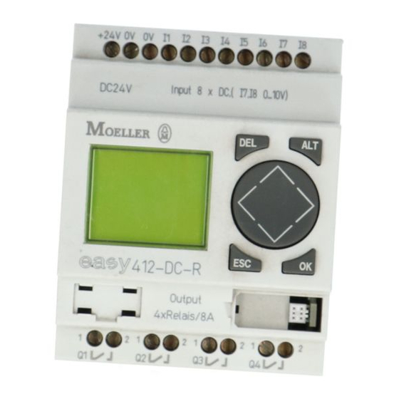
- Page 8 Simply “easy” Overview of “easy” D EL AL T ES C D EL AL T ES C a Power supply b Inputs c Buttons d Socket for memory card or PC interface cable e Output terminals f LCD display For Immediate Delivery call KMParts.com at (866) 595-9616...
-
Page 9: Mounting "Easy
“easy” Control Relay Mounting “easy” Mounting on top-hat rail Hook “easy” to the top edge of the top-hat rail and hinge into place while pressing down slightly as shown by the arrows. “easy” will clip into place and will be secured by the built-in spring mechanism without needing screws. - Page 10 Connecting “easy” Inputs EASY 412-DC-... l = 2 mA/24 V I7, I8 = 2.2 mA/24 V 15 V +24 V l7, l8 ˜ > 1 A U e = 24 V +10 V (20.4–28.8 V I e = 80 mA 10 V 0.5 Nm 3.5 mm...
- Page 11 “easy” Control Relay Outputs EASY 412-AC-..., EASY 412-DC-R... 24 V 10 000 000 115 V 230 V 1000 W 58 W 25.000 8 A/B 16 L1, L2, L3 (115/230 V + 24 V Outputs EASY 412-DC-T... Suppressor circuit + 24 V 33 V +24 V +24 V 0 V 0 V Q1 Q2 Q3 Q4...
- Page 12 Connecting “easy” Inputs EASY 620-DC-TC I1–I6, I9–I12 = 3.3 mA 28.8 V 24 V 15 V I7, I8 = 2.2 mA 24 V +24 V l7, I8 > 1 A +10 V = 24 V (20.4–28.8 V = 140 mA 10 V 0.5 Nm 3.5 mm...
- Page 13 “easy” Control Relay Outputs EASY 618-AC-RC 24 V 10 000 000 115 V 230 V 1000 W 58 W 25.000 8 A/B 16 L1, L2, L3 (115/230 V + 24 V Outputs EASY 620-DC-TC Suppressor circuit + 24 V 33 V +24 V Q1 Q2 Q3 Q4 Q5 Q6 Q7...
-
Page 14: Easy" Operating Principle
“easy” operating principle “easy” operating “easy” operating buttons principle DEL: Delete object in the circuit diagram A LT ALT: Special functions in the circuit diagram ÍÚ: ú í Cursor buttons Move cursor, Select menu item, Choose contact numbers, values, time etc. OK: Next menu level, store your entry ESC: Last menu level, cancel your entry Moving through menus and choosing values... - Page 15 “easy” Control Relay EASY 412-...status display I12345678 Inputs ââ###### MO Weekday â### 12:50 Time Q1234 Output RUN/STOP mode terminals â On/ # Off Status displayEASY 618-..., EASY 620-... 1...5..8..Inputs Retention Debounce/P buttons MO 02:00 Day, time Stop mode .2..5..8 RUN Output Mode terminals...
- Page 16 “easy” operating principle Cursor display The cursor blinks alternately: WINTER TIME ê : MO Full blinking cursor ú í TIME : 01ê25 Move cursor with In circuit diagram also with ÍÚ WINTER TIME Value ú í : MO Change position with Change values with ÍÚ...
- Page 17 “easy” Control Relay Circuit diagram symbols Cursor button as input Contact for input Contact for output Contact for marker relay Contact for timer relay Contact for counter relay Ö Contact for time switch Analog comparator contact Contact for text marker relay Contact for jump relay Reserve contact for relay Contact for marker relay...
- Page 18 “easy” operating principle Menu structure Main menu without optional password protection STOP: Circuit diagram menu RUN: Power flow display Main menu Parameter PROGRAM... display Circuit diagram STOP PARAMETER SET CLOCK PROGRAM Parameters DELETE PROG CARD... PROGRAM DELETE ? DELETE PROG CARD...
- Page 19 “easy” Control Relay Main menu with password protection Password entry Main menu unlock Four wrong “easy” entries PASSWORD... DELETE ALL Password PARAMETER SET CLOCK.. Correct entry Status display PASSWORD... System menu EASY 412-..., operating system V 1.0 Password entry System Set password PASSWORD...
- Page 20 “easy” operating principle System menu EASY 412-..., operating system from V 1.2, EASY 618-AC-RC, EASY 620-DC-TC Password entry System Set password PASSWORD... Password SYSTEM Password entry GB D F E I.. Change password CHANGE PW Password ACTIVATE CHANGE PW ACTIVATE ACTIVATE PASSWORD...
- Page 21 For Immediate Delivery call KMParts.com at (866) 595-9616...
-
Page 22: Drawing A Circuit With "Easy
Drawing a Circuit with “easy” Operation of “easy” Buttons for drawing circuit diagrams Delete circuit connection, contact, relay or empty line in the circuit diagram Toggle between break and make contact Connect contacts and relays Add circuit connections ÍÚ Change value Move cursor up and down ú... -
Page 23: Setting The Menu Language
Drawing a Circuit with “easy” Setting the menu Switching on “easy” for the first time language Choose menu language Choose language with the cursor keys ÍÚ ENGLISH English German GB D F E I.. French Spanish Italian EASY 600 also supports the following languages: Portuguese Dutch Swedish... -
Page 24: Setting The Time
Setting the time Setting the time A clock is only provided in “easy” models with the type designation “...-C”. Switch to the Set Clock menu I12345678 1...5..8..PROGRAM... ######## MO #### 14:15 MO 02:00 PARAMETER Q1234 STOP .2..5..8 RUN SET CLOCK.. PROGRAM... -
Page 25: Choose "Easy" Operating Mode
Drawing a Circuit with “easy” Winter/summer time (DST) Display: SUMMER TIME SET CLOCK Winter time is set SUMMER TIME Display: WINTER TIME Summer time is set Toggle settings Exit menu Choose “easy” The two “easy” operating modes are RUN or STOP. operating mode RUN: “easy”... -
Page 26: Easy"-Circuit Diagram Elements
“easy” circuit diagram elements EASY 412-DC-... 4 marker relays (markers) 1 timing relay 1 counter EASY 620-DC-TC, EASY 618-AC-RC 12 marker relays (markers), text display 2 timing relays 4 counters For further information see AWB 2528-1304 GB. “easy” circuit diagram Contacts elements Contact type... - Page 27 Drawing a Circuit with “easy” Relays Relay type “easy” EASY 412 EASY 6... Coil Param symbol function eter I1...I8 I1...I12 “easy” input terminal – – P1...P4 P1...P4 P button contact (cursor keys) – – Q1...Q4 Q1...Q8 “easy” output relay contact –...
- Page 28 “easy” circuit diagram elements Basic relays with contactor function Ä Impulse relay ä Latching relay For Immediate Delivery call KMParts.com at (866) 595-9616...
-
Page 29: Example: Creating A Circuit Diagram
Drawing a Circuit with “easy” Example: creating a Interconnecting contacts and relays circuit diagram Conventional circuit “easy” circuit diagram Connecting up “easy” Connect S1 to “easy” input terminal I1 Connect S2 to “easy” input I2 Connect load H1 to “easy” output Q1 “easy”... - Page 30 Example: creating a circuit diagram Insert contact “I2” ê I1-I2 ê Draw connection between contact and relay coil I1-I2l I1-I2 ê I1-I2---l I1-I2--- ê Choose relay coil “Q1” I1-I2--- ê I1-I2--- ÄQ1 I1-I2--- ÄQ1 I1-I2----ÄQ1 ê For Immediate Delivery call KMParts.com at (866) 595-9616...
- Page 31 Drawing a Circuit with “easy” Change operating mode “easy” circuit diagram I1-I2----ÄQ1 PROGRAM DELETE PROG PROGRAM... PARAMETER PROGRAM... SET CLOCK.. PARAMETER SET CLOCK.. “easy” now in RUN mode Test circuit diagram PROGRAM... PROGRAM... PROGRAM.. STOP PARAMETER PARAMETER SET CLOCK.. SET CLOCK.. Power flow display I1-I2----ÄQ1 For Immediate Delivery call KMParts.com at (866) 595-9616...
- Page 32 Example: creating a circuit diagram Operate switch “S1” and “S2” “S1” on I 1 - I 2 - ---Q 1 I1-I2----ÄQ1 “S2” on I1-I2----ÄQ1 Relay “Q1” picks up Return to status display with ESC I1-I2----ÄQ1 I12345678 12..ââ###### MO â### 13:34 MO 02:00 Q1234 1..
-
Page 33: Function Relay Types
Drawing a Circuit with “easy” Function relay types Circuit diagram symbol Function relay type Timing relay with on delay with and without random switching Timing relay, off-delayed with and without random switching Timing relay, single pulse Timing relay, flashing Counter relay, up/down counter Time switch, weekday/time (only in “easy”... - Page 34 Function relay types Timing relay, off-delayed, with â ?â and without random switching With random switching, the relay contact switches randomly at any time up to the specified time value (shown shaded in figure). Timing relay, single pulse ü For Immediate Delivery call KMParts.com at (866) 595-9616...
- Page 35 Drawing a Circuit with “easy” Timing relay, flashing Ü Flash frequency ----------------------------- - Setpoint Parameter display for timing relays ü w00.00g Switch function Curr. time 30.00 Time units Setpoint Ä sTRG Trigger (connected) Relay no. yRES Reset (not connected) Parameter display (access) For Immediate Delivery call KMParts.com at (866) 595-9616...
- Page 36 Function relay types Counter relay Setpoint = 6 Parameter display for counter relays 0230 g0000 Setpoint Curr. value Ä sDIR n Opt. direction (connected) Setpoint Ä sCNT d Opt. counter (connected) Relay no. Ä yRES b Reset (not connected) Parameter display (access) For Immediate Delivery call KMParts.com at (866) 595-9616...
- Page 37 Drawing a Circuit with “easy” Time switch Ö Example: Time switch “ 1“ switches on Mondays to Fridays between 6:30 and 9:00 and between 17:00 and 22:30. fMO-FRg fMO-FRg dÖ1 dÖ1 ON s06:30n A ON s17:00n B OFFy09:00b + OFFy22:30b + Parameter display for time switches Week day(s) from - to n01:00dÖ1...
- Page 38 Function relay types Analog comparator Available functions: I8, I7 Setpoint, I7 Setpoint Setpoint, I8 Setpoint The analog comparator can compare voltages from 0 V to 10 V (setpoints “0.0” to “10.0”). Analog signals of sensors typically fluctuate by several millivolts. For stable set and reset switching the setpoints should differ by at least 0.2 V (switching hysteresis).
- Page 39 Drawing a Circuit with “easy” Text display (Marker) The markers can be used to display eight freely definable texts. Each text block can display up to 48 characters from the easy display character set (ASCII + easy special characters). If the coil of a marker is “1”, the text entered via EASY-SOFT V 2.0 will be displayed.
-
Page 40: Example: Using A Function Relay
Example: using a function relay Example: using a Conventional circuit “easy” circuit diagram function relay “easy” switches H1 with 10 seconds delay. “easy” circuit diagram I1-I2----ÄM1 M1-------TT1 T1-------ÄQ1 Select marker relay Start Circuit from first example Position cursor on “Q” I1-I2----ÄQ1 I1-I2----ÄQ1 I1-I2----ÄM1... - Page 41 Drawing a Circuit with “easy” output relay I1-I2----ÄM1 I1-I2----ÄM1 ê I1-I2----ÄM1 M1------ ÄQ1 For Immediate Delivery call KMParts.com at (866) 595-9616...
- Page 42 Example: using a function relay Select Trigger relay for time I1-I2----ÄM1 I1-I2----ÄM1 M1------ ÄQ1 M1-------TT1 I1-I2----ÄM1 M1-------TT1 ê Insert timing relay contact I1-I2----ÄM1 I1-I2----ÄM1 M1-------TT1 M1-------TT1 ê I1-I2----ÄM1 M1-------TT1 Select parameter access I1-I2----ÄM1 M1-------TT1 n00.00n Ä sTRG yRES For Immediate Delivery call KMParts.com at (866) 595-9616...
- Page 43 Drawing a Circuit with “easy” Set “10 seconds” n00.00n n00.00n Ä sTRG Ä sTRG yRES yRES n10.00n Ä sTRG yRES back to circuit diagram Connect timing relay contact to new output relay I1-I2----ÄM1 I1-I2----ÄM1 M1-------TT1 M1-------TT1 ê I1-I2----ÄM1 M1-------TT1 T1-------ÄQ1 ê...
-
Page 44: Basic Circuits
Basic circuits Basic circuits Significance of logic values “0” Make contact open, break contact closed, relay coil not energised “1” Make contact closed, break contact open, relay coil energised Negation (NOR) i1-------ÄQ1 Permanent contact ---------ÄQ1 Impulse relay I1-------äQ1 State Q1 Series connection (AND) I1-I2-I3-ÄQ1 i1-i2-i3-ÄQ2... - Page 45 Parallel connection (OR) I1u------ÄQ1 i1u------ÄQ2 Changeover circuit (XOR) I1-i2u---ÄQ1 i1-I2k Latching circuit I1uI2----ÄQ1 Contact Q1 Coil Q1 alternatively: I1-------SQ1 i2-------RQ1 For Immediate Delivery call KMParts.com at (866) 595-9616...
-
Page 46: Easy" Interface Socket
“easy” Interface Socket The “easy” interface socket, which is hidden beneath a protective cap, lets you plug in the optional “easy” memory card or connect “easy” to a PC using the optional PC interface cable and the EASY-SOFT software. You can then copy your circuit diagrams to and from the PC and/or memory card. - Page 47 “easy” Interface Socket Loading or storing the circuit diagram You can only transfer the circuit diagram from “easy” to the card or vice versa in STOP mode. “EASY->CARD”: Transfer circuit EASY -> CARD diagram and parameter settings CARD -> EASY from “easy”...
-
Page 48: Technical Data
Technical Data Technical data Weight 200 g, 300 g (EASY 600) Ambient temperature, –25 to 55 °C (operation) Protection class IP 20 Emitted interference, inter- EN 55011, EN 55 022, Class B ference immunity Standards and regulations EN 50 178 Approvals UL, CSA “easy”... - Page 49 Technical Data EASY 412-DC-... EASY 412-AC-... EASY 618-... EASY 620-..R ...RC ...TC ...TCX ...R ...RC ...RCX ...AC-RC ...DC-TC Input/output simu- EASY 412-DC-SIM – – – – – lator Mounting feet ZB 4-101-GF1: For EASY 412-... 3 feet min. 3 Documentation Training Guide (AWB 2528-1316 GB), User Guide (AWB 2528-1304 GB), Application Guide (TB 2528-025 GB)
- Page 50 “easy” models Dimensions EASY 618-..., EASY 620 16.25 16.25 47.5 56.5 107.5 For Immediate Delivery call KMParts.com at (866) 595-9616...
- Page 51 Technical Data For Immediate Delivery call KMParts.com at (866) 595-9616...
-
Page 52: Index
Index Accessories ..............45 Accuracy Analog comparator ............. 35 Analog comparator ............35 Hysteresis ..............35 AND circuit ..............41 Basic circuit Impulse relay .............. 41 Parallel connection ............. 42 Permanent contact ............. 41 Basic circuits Example ..............41 Break contact ..............23 Buttons ................ - Page 53 Index Contactor function ............25 Contacts Overview ..............23 Counter relay ..............33 Parameter display ............33 Cursor display ..............13 Dimensions, “easy” ............46 Overview of “easy” ............5 Example Basic circuits .............. 41 Circuit diagram ............26 Contacts and relays ............ 26 Example of function relay ..........
- Page 54 Index Make contact ..............23 Marker ................36 Memory card (optional) ..........43 Menu guidance .............. 11 Menu language Changing ..............20 Menu structure ............... 15 Models ................45 Mounting ................6 Negation ................. 41 NOT ................41 Operating buttons ............11 OR circuit ...............
- Page 55 Index Symbols in circuit diagram ..........14 System menu ..............16 Terminals, inputs/outputs ..........6 Text display ..............36 Time switch ..............34 Parameter display ............34 Timing relays ............30–32 Parameter display ............32 Transfer cable ..............43 Winter time ..............22 XOR circuit ..............
Need help?
Do you have a question about the EASY 412-DC Series and is the answer not in the manual?
Questions and answers