
Related Manuals for Moeller easy500


Summary of Contents for Moeller easy500
- Page 1 Building Automation Industrial Automation Systems User Manual easy500, easy700 Control Relay 05/04 AWB2528-1508GB Think future. Switch to green. For Immediate Delivery call KMParts.com at (866) 595-9616...
-
Page 2: For Immediate Delivery Call Kmparts.com At (866)
No part of this manual may be reproduced in any form (printed, photocopy, microfilm or any other process) or processed, duplicated or distributed by means of electronic systems without written permission of Moeller GmbH, Bonn. Subject to alteration without notice. For Immediate Delivery call KMParts.com at (866) 595-9616... - Page 3 Warning! Dangerous electrical voltage! Before commencing the installation • Disconnect the power supply of the device. • Suitable safety hardware and software measures should be implemented for the • Ensure that devices cannot be accidentally I/O interface so that a line or wire breakage restarted.
- Page 4 • Measures should be taken to ensure the • Wherever faults in the automation system proper restart of programs interrupted may cause damage to persons or property, after a voltage dip or failure. This should external measures must be implemented to not cause dangerous operating states even ensure a safe operating state in the event for a short time.
-
Page 5: Table Of Contents
05/04 AWB2528-1508GB Content About This Manual Device designation Writing conventions easy Target readership Proper use – Improper use Overview Versions – Type reference easy operation – Buttons – Moving through menus and choosing values – Selecting main and system menu –... - Page 6 05/04 AWB2528-1508GB Content Installation Mounting Connecting the expansion device Terminals – Tools – Cable cross-sections Connecting the power supply – Cable protection – Supplying AC units – Supplying DC units Connecting the inputs – Connecting easy AC digital inputs – Connecting easy DC digital inputs –...
- Page 7 Analog value comparator/threshold value switch 104 – Circuit diagram display with analog value comparator – Compatibility between easy400 and easy500, easy600 and easy700 – Parameter display in RUN mode – Resolution of the analog inputs – Function of the analog value comparator Counters –...
- Page 8 05/04 AWB2528-1508GB Content 7-day time switch – Parameter display and parameter set for 7-day time switch: – Changing time switch channel – Function of the 7-day time switch Operating hours counter – Value range of the operating hours counter – Accuracy of the operating hours counter –...
- Page 9 05/04 AWB2528-1508GB Content Basic circuits – Negation (contact) – Negation (coil) – Maintained contact – Series circuit – Parallel circuit – Parallel circuit operating like a series connection of make contacts – Parallel circuit operating like a series connection of break contacts –...
- Page 10 05/04 AWB2528-1508GB Content Activating and deactivating the P buttons – Activating the P buttons – Function of the P buttons – Deactivating the P buttons Startup behaviour – Setting the startup behaviour – Behaviour when the circuit diagram is deleted 226 –...
- Page 11 05/04 AWB2528-1508GB Content Inside easy easy circuit diagram cycle – easy operation and effects on circuit diagram creation Delay times for inputs and outputs – Delay times with easy-DA and easy-DC basic units – Delay time with easy-easy-AB, easy-AC basic units –...
- Page 12 05/04 AWB2528-1508GB Content Appendix Dimensions Technical Data – General – Special approvals – Power supply – Inputs – Relay outputs – Transistor outputs List of the function relays – Usable contacts – Available function relays – Names of relays – Names of function relay –...
-
Page 13: About This Manual
05/04 AWB2528-1508GB About This Manual This manual describes the installation, commissioning and programming (circuit diagram generation) of the easy500 and easy700 control relay. Specialist electrical training is needed for commissioning and creating circuit diagrams. When active components such as motors or pressure cylinders are controlled, parts of the system can be damaged and persons put at risk if the device is connected or programmed incorrectly. -
Page 14: Writing Conventions
05/04 AWB2528-1508GB About This Manual easy-DC for EASY512-DC... EASY6..-DC..., EASY719-DC... and EASY721-DC... easy-E for EASY2.., EASY618-AC-RE, EASY618-DC-RE and EASY620- DC-TE Writing conventions Symbols used in this manual have the following meanings: indicates actions to be taken. Attention! Warns of a hazardous situation that could result in damage to the product or components. -
Page 15: Easy
05/04 AWB2528-1508GB easy Target readership easy must only be installed and connected up by trained electricians or other persons who are familiar with the installation of electrical equipment. Specialist electrical training is needed for commissioning and creating circuit diagrams. When active components such as motors or pressure cylinders are controlled, parts of the system can be damaged and persons put at risk if easy is connected or programmed incorrectly. -
Page 16: Overview
05/04 AWB2528-1508GB easy Overview POW ER COM -ERR Figure 1: easy basic units and expansion devices For Immediate Delivery call KMParts.com at (866) 595-9616... - Page 17 05/04 AWB2528-1508GB Overview Legend for figure 1: a easy500 basic unit b easy600 I/O expansion c EASY202-RE output expansion d EASY200-EASY coupling device e EASY-LINK-DS data connector f EASY204-DP PROFIBUS-DP slave gateway g EASY205-ASI AS-Interface slave gateway h EASY221-CO CANopen gateway...
- Page 18 05/04 AWB2528-1508GB easy If you prefer to wire up easy from a PC, then use EASY-SOFT- BASIC. EASY-SOFT-BASIC allows you to create and test your circuit diagram on the PC. EASY-SOFT-BASIC is also used to print out your circuit diagram in DIN, ANSI or easy format. For Immediate Delivery call KMParts.com at (866) 595-9616...
-
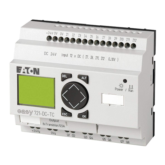
Page 19: Versions
05/04 AWB2528-1508GB Overview Versions easy basic units at a glance D EL AL T ES C D EL AL T ES C Figure 2: Versions a Power supply b Inputs c Status LED d Buttons e Interface socket for memory card or PC connection f Outputs g LCD display For Immediate Delivery call KMParts.com at (866) 595-9616... - Page 20 05/04 AWB2528-1508GB easy easy basic units with stand-alone MFD-80.., MFD-CP4-500 HMI unit Figure 3: Overview with stand-alone HMI unit a easy500 basic units b easy700 basic units c MFD device d Power supply/communication module with MFD-CP4-500 interface cable For Immediate Delivery call KMParts.com at (866) 595-9616...
-
Page 21: Type Reference
4, 5 = 71.5 mm (4 SU), RC = 4 or 5 6, 7= 107.5 mm (6SU), RC = 6 or 7 easy control relay Table 1: Overview of comparable easy400 types with easy500 and easy600 with easy700 easy400, easy600 easy500, easy700 –... - Page 22 05/04 AWB2528-1508GB easy easy400, easy600 easy500, easy700 EASY412-DC-RCX EASY512-DC-RCX EASY412-DC-TC EASY512-DC-TC EASY412-DC-TCX EASY512-DC-TCX – EASY719-AB-RC – EASY719-AB-RCX EASY619-AC-RC EASY719-AC-RC EASY619-AC-RCX EASY719-AC-RCX – EASY719-DA-RC – EASY719-DA-RCX EASY619-DC-RC EASY719-DC-RC EASY619-DC-RCX EASY719-DC-RCX EASY621-DC-TC EASY721-DC-TC EASY621-DC-TCX EASY721-DC-TCX For Immediate Delivery call KMParts.com at (866) 595-9616...
-
Page 23: Easy Operation
05/04 AWB2528-1508GB Overview easy operation Buttons DEL: Delete object in circuit diagram ALT: Special functions in circuit diagram, Status display ÍÚ: ú í Cursor buttons Move cursor Select menu items Set contact numbers, contacts and values OK: Next menu level, Save your entry ESC: Previous menu level, Cancel Moving through menus and choosing values Show System menu... -
Page 24: Selecting Main And System Menu
05/04 AWB2528-1508GB easy Selecting main and system menu Status display easy500: 8 inputs, 4 outputs I .2..5..MO 02:00 ..34 . .2 6.. password PROGRAM... SECURITY... Current selection flashes in STOPå RUN SYSTEM... the easy menu PARAMETER LANGUAGE... INFO... SET CLOCK... -
Page 25: Easy Status Display
.2..5..34 01.04.2004 ..34 easy Status display .2..5..MO 11:50 .2..5..Q ..34..STOP 01.04.2002 Q ..34..STOP easy500: input 1 to 8, easy700: input 1 to 12 1..9... Inputs AC P- MO 10:42 Weekday/Time or Weekday/Date 1..7. RUN Outputs RUN/STOP mode... -
Page 26: Advanced Status Display
05/04 AWB2528-1508GB easy Advanced Status display 12...6.89... AC P- Retention/Debounce AC expansion ok/P buttons 17.03.04 Startup behaviour 123.5.78 RUN : Retention switched on : Debounce switched on : AC expansion functioning correctly : DC expansion functioning correctly : Bus coupling module detected GW flashes: Only easy200-easy detected. -
Page 27: Menu Structure
05/04 AWB2528-1508GB Overview Menu structure Main menu without password protection You access the main menu by pressing OK. STOP: Circuit diagram display Main menu PROGRAM..Æ PROGRAM... STOP å RUN DELETE PROG Circuit diagram PARAMETER CARD Parameter INFO... æ display SET CLOCK.. SAVE arrows CANCEL... - Page 28 05/04 AWB2528-1508GB easy Main menu PROGRAM..Æ STOP RUN å PARAMETER INFO... æ SET CLOCK.. Parameter display PROGRAM..Æ STOP RUN å T1 X T1 X PARAMETER... 10.000 T2 Ü M:S + INFO... æ C1 N SET CLOCK.. PROGRAM..Æ Information display of the device STOP RUN å...
- Page 29 05/04 AWB2528-1508GB Overview Main menu Only one selection is possible. PROGRAM... STOP RUN Æ PARAMETER... INFO... SET CLOCK.. CLOCK.æ SUMMER TIME. NONE åÆ RULE... æ SET CLOCK.. SUMMER TIME. NONE Æ RULE... SUMMER START SUMMER END æ --Æ DD.MM:00.00æ HH:MM:00:00 DIFF: 0:00 NONE...
- Page 30 05/04 AWB2528-1508GB easy Main menu with password protection Main menu Unlocking Password entry easy PASSWORD.. Æ DELETE ALL STOP RUN å Password Example: PARAMETER... Four wrong entries Password only INFO... æ (if enabled) SET CLOCK.. on program Status display Correct entry PASSWORD...
- Page 31 05/04 AWB2528-1508GB Overview System menu SECURITY... DEBOUNCE å SYSTEM... P-BUTTONS LANGUAGE... RUN MODE å CONFIGURATOR CARD MODE SECURITY... ENGLISH Æ SYSTEM... DEUTSCH å LANGUAGE... FRANCAIS CONFIGURATOR ESPANOL æ Only one selection is possible. ITALIANO PORTUGUES NEDERLANDS SVENSKA POLSKI TURKCE CESKY MAGYAR SECURITY...
-
Page 32: Selecting Or Toggling Between Menu Items
05/04 AWB2528-1508GB easy Selecting or toggling between menu items Í Ú Cursor PROGRAM... STOP PARAMETER INFO Select or toggle Cursor display The cursor flashes. HH:MM '4:23 Ê DD.MM 17.03 Full cursor YEAR 2004 ú í • Move cursor with Í Ú •... -
Page 33: Setting Values
05/04 AWB2528-1508GB Overview Setting values Í Ú Select value HH:MM 14:23 ú í DD.MM 17.03 Select digit YEAR 2004 ÍÚ Change value at digit Store entries Values Digits Current value at the Retain previous value position (can be changed, Cursor = 3) For Immediate Delivery call KMParts.com at (866) 595-9616... - Page 34 05/04 AWB2528-1508GB For Immediate Delivery call KMParts.com at (866) 595-9616...
-
Page 35: Installation
05/04 AWB2528-1508GB Installation easy must only be installed and wired up by trained electricians or other persons familiar with the installation of electrical equipment. Danger of electric shock Never carry out electrical work on the device while the power supply is switched on. Always follow the safety rules: •... - Page 36 05/04 AWB2528-1508GB Installation For ease of wiring, leave a gap of at least 30 cm between easy terminals and the wall or adjacent devices. Figure 4: Clearances to easy Mounting on top-hat rail Hook easy to the top edge of the top-hat rail and hinge into place while pressing down slightly.
- Page 37 The fixing brackets are available as an accessory. easy600 and easy700: Fasten each device with at least three fixing brackets. EASY200-EASY: easy500: easy600, easy700: Figure 5: Using a mounting plate For Immediate Delivery call KMParts.com at (866) 595-9616...
-
Page 38: Connecting The Expansion Device
05/04 AWB2528-1508GB Installation Connecting the expansion device Figure 6: Connecting expansion units For Immediate Delivery call KMParts.com at (866) 595-9616... -
Page 39: Terminals
AC, easy-DA with 12 V DC and easy-DC with 24 V DC are provided in the section “Technical Data”, page 262. The easy500 and easy700 basic units run a system test for two seconds after the power supply has been switched on. -
Page 40: Supplying Ac Units
05/04 AWB2528-1508GB Installation Supplying AC units Supplying AC basic units EASY…-AB-RC(RCX), EASY…-AC-R(RC, RCX) Figure 7: Power supply on the AC basic units Supplying AC expansion units EASY…-AC-.E E+ E- Figure 8: Power supply on the AC expansion units For Immediate Delivery call KMParts.com at (866) 595-9616... -
Page 41: Supplying Dc Units
05/04 AWB2528-1508GB Connecting the power supply Applies to easy-AC devices with a power supply greater than 24 V AC: • The voltage terminals for phase L and neutral conductor N have been reversed. • This enables the easy interface (for memory card or PC connection) to have the full connection voltage of the phase conductor (100 to 240 V AC). - Page 42 05/04 AWB2528-1508GB Installation Supplying DC expansion units EASY…-DC-.E L01+ L01- E+ E- 24 V Figure 10: Power supply on the DC expansion units easy-DC and easy-DA are protected against reverse polarity. To ensure that easy works correctly, ensure that the polarity of each terminal is correct. Cable protection Connect on easy a cable protection (F1) rated for at least 1 A (slow).
-
Page 43: Connecting The Inputs
05/04 AWB2528-1508GB Connecting the inputs Connecting the inputs easy inputs switch electronically. Once you have connected a contact via an input terminal, you can reuse it as a contact in your easy circuit diagram as often as you like. +24 V Figure 11: Connecting the inputs Connect to the easy input terminals contacts such as pushbuttons, switches, relay or contactor contacts, proximity... - Page 44 05/04 AWB2528-1508GB Installation Connecting easy AC digital inputs on the basic unit Figure 12: Connecting easy-AC and easy-AB digital inputs Connecting AC digital inputs on the expansion device E+ E- R11 R12 Figure 13: Connecting EASY...-AC-E digital inputs For Immediate Delivery call KMParts.com at (866) 595-9616...
- Page 45 Connecting the inputs Table 2: easy-AB input signal values Input signal voltage range Input current OFF signal ON signal easy500/ I1 to I6 0 to 6 V AC 14 to 26.4 V AC 4 mA at 24 V AC easy700 I7, I8...
- Page 46 05/04 AWB2528-1508GB Installation For longer lengths connect in series a diode (e.g. 1N4007) for 1 A, min. 1000 V reverse voltage, to the easy input. Ensure that the diode is pointing towards the input as shown in the circuit diagram, otherwise easy will not detect the 1 state.
- Page 47 05/04 AWB2528-1508GB Connecting the inputs Increasing the input current The following input circuit can be used in order to prevent interference and also when using two-wire proximity switches: 100 nF/275 V h Figure 15: Increasing the input current When using a 100 nF capacitor the drop-off time of the input increases by 80 (66.6) ms at 50 (60) Hz.
-
Page 48: Connecting Easy Dc Digital Inputs
05/04 AWB2528-1508GB Installation Complete devices for increasing the input current are available under the type reference EASY256-HCI. Figure 17: easy with EASY256-HCI The increased capacitance increases the drop-off time by approx. 40 ms. Connecting easy DC digital inputs Use input terminals I1 to I12, R1 to R12 to connect pushbutton actuators, switches or 3 or 4-wire proximity switches. - Page 49 05/04 AWB2528-1508GB Connecting the inputs Connecting DC digital inputs on the basic unit +...V DC : +24 V DA : +12 V Figure 18: Connecting easy-DC, easy-DA digital inputs Connecting DC digital inputs on the expansion device +24 V E+ E- R11 R12 +24V Input 24 V...
-
Page 50: Connecting Easy Dc Analog Inputs
Installation Table 4: easy-DC input signals Input signal voltage range Input current OFF signal ON signal easy500/ I1 to I6 0 to 5 V 15 to 28.8 V 3.3 mA at 24 V DC easy700 I7, I8 greater than 8 V DC 2.2 mA at 24 V... - Page 51 05/04 AWB2528-1508GB Connecting the inputs Caution! Analog signals are more sensitive to interference than digital signals. Consequently, greater care must be taken when laying and connecting the signal lines. Incorrect switching states may occur if they are not connected correctly. Safety measures with analog signals Use shielded twisted pair cables to prevent interference with the analog signals.
- Page 52 05/04 AWB2528-1508GB Installation Power supply of easy-AB devices and analog inputs With easy-AB devices that process analog signals, the device must be fed via a transformer so that the device is isolated from the mains supply. The neutral conductor and the reference potential of the DC power feed of analog sensors must be electrically connected.
- Page 53 05/04 AWB2528-1508GB Connecting the inputs Analog setpoint potentiometer, easy-AB, easy-DA, easy-DC +12 V +...V Figure 21: Analog setpoint potentiometer with own power feed Use a potentiometer with a resistance of 1 k , e.g. 1 k , 0.25 W. easy-DC analog setpoint potentiometer 1.3 kO/0.25 W 1 kO/0.25 W +...V...
- Page 54 05/04 AWB2528-1508GB Installation Brightness sensor, easy-AB, easy-DA, easy-DC 12 V 0...10 V +12 V +...V Figure 23: Connection of a brightness sensor, analog input Temperature sensor, easy-DA, easy-DC +24 V –0 V 0...10 V –35...55 ˚C +...V Figure 24: Connection of the temperature sensor, analog input For Immediate Delivery call KMParts.com at (866) 595-9616...
-
Page 55: Connecting High-Speed Counters And Frequency Generators
05/04 AWB2528-1508GB Connecting the inputs 20 mA sensor 4 to 20 mA (0 to 20 mA) sensors can be connected easily without any problem using an external 500 resistor. 4...20 mA +...V DC : +24 V DA : +12 V Figure 25: Connection 0 (4) to 20 mA sensor output, analog input Analog sensor The following values apply:... - Page 56 05/04 AWB2528-1508GB Installation • I3 = C15 frequency counter • I4 = C16 frequency counter Pulse shape of count signals: easy processes square wave signals. Mark-to-space ratio of count signals: We recommend a mark-to-space ratio of 1:1. If this is not the case: The minimum pulse or pause duration is 0.5 ms.
-
Page 57: Connecting The Outputs
05/04 AWB2528-1508GB Connecting the outputs Inputs that are used as high-speed counter inputs should not be used in the circuit diagram as contacts. If the counter frequency is high: Not all the signals of the high-speed counter can be monitored for processing in the circuit diagram. easy will only process a randomly logged state. -
Page 58: Connecting Relay Outputs
05/04 AWB2528-1508GB Installation Connecting relay outputs EASY512-..-R.. 24 V H 8 A 10 000 000 115 V 230 V 1000 W 0 V H, N 10 x 58 W 25 000 F 8 A/B 16 L1, L2, L3 (115/230 V h) + 24 V H Figure 28: EASY512-..-R.. - Page 59 05/04 AWB2528-1508GB Connecting the outputs EASY618-..-RE 24 V H 8 A 10 000 000 115 V h 8 A 230 V h 8 A 1000 W 0 V H, N 10 x 58 W 25 000 F 8 A/B 16 L1, L2, L3 (115/230 V h) + 24 V H Figure 30: EASY618-..-RE..
-
Page 60: Connecting Transistor Outputs
05/04 AWB2528-1508GB Installation Connecting transistor outputs EASY512-..-T.. +24 V Q1 Q2 Q3 Q4 F10 A 0 V H f 2.5 A 24 V 0.5 A 0.5 A + 24 V H 20.4 – 28.8 V H 5 W/24 V Figure 31: EASY512-..-T.. transistor outputs EASY7..-..-T.. - Page 61 05/04 AWB2528-1508GB Connecting the outputs EASY620-..-TE S1 S2 S3 S4 S5 S6 S7 S8 +24 V F10 A 0 V H + 24 V H 24 V H 0.5 A 0.5 A f 2.5 A (20.4 – 28.8 V H) 5 W/24 V Figure 33: EASY620-..-TE transistor outputs Parallel connection:...
- Page 62 05/04 AWB2528-1508GB Installation If inductive loads are not suppressed, the following applies: Several inductive loads should not be switched off simultaneously to avoid overheating the driver blocks in the worst possible case. If in the event of an emergency stop the +24 V DC power supply is to be switched off by means of a contact, and if this would mean switching off more than one controlled output with an inductive load, then you must...
-
Page 63: Expanding Inputs/Outputs
05/04 AWB2528-1508GB Expanding inputs/outputs Expanding inputs/outputs You can add expansion units to the following easy models in order to increase the number of inputs and outputs: Expandable easy Expansion units basic units EASY7..-..-R.. EASY618-..-RE 115/230 V AC power supply EASY7..-..-T.. •... -
Page 64: Remote Expansion
05/04 AWB2528-1508GB Installation Warning! The following electrical isolation is implemented between the EASY7..-..-.C. basic unit and the expansion device (isolation always in local connection of expansion unit) • Basic isolation 400 V AC (+10 %) • Safe isolation 240 V AC (+10 %) Units may be destroyed if the value 400 V AC +10 % is exceeded, and may cause the malfunction of the entire system or machine! - Page 65 05/04 AWB2528-1508GB Expanding inputs/outputs E+ E– EASY719-… EASY6…-RE EASY721-… EASY6…-TE EASY200- EASY E+ E– = 300/500 V EASY…-AC-…E Figure 36: Connecting remote expansion units to easy Terminals E+ and E- of the EASY200-EASY are protected against short-circuits and polarity reversal. Functionality is only ensured if “E+”...
-
Page 66: Connecting Bus Systems
The range and the functions of the bus gateways are being continually further developed. The current Moeller product line catalogue and the Internet online catalogue contain those bus gateways that are currently available. For Immediate Delivery call KMParts.com at (866) 595-9616... -
Page 67: Commissioning
05/04 AWB2528-1508GB Commissioning Switching on Before switching on easy, check that you have connected the power supply terminals and inputs correctly: • 24 V AC version easy-AB – Terminal L: Phase conductor L – Terminal N: Neutral conductor N – Terminals I1 to I12: Actuation via same phase conductor L •... -
Page 68: Setting The Menu Language
05/04 AWB2528-1508GB Commissioning Setting the menu When you switch on easy for the first time, you will be asked language to select the menu language. Í Ú Use the cursor buttons to select the language ENGLISH å required. DEUTSCH – English FRANCAIS –... -
Page 69: Easy Operating Modes
05/04 AWB2528-1508GB Setting the menu language easy operating modes easy has two operating modes - RUN and STOP. In RUN mode easy continuously processes a stored circuit diagram until you select STOP or disconnect the power. The circuit diagram, parameters and the easy settings are retained in the event of a power failure. -
Page 70: Creating Your First Circuit Diagram
05/04 AWB2528-1508GB Commissioning Creating your first circuit The following small circuit diagram takes you step by step diagram through wiring up your first easy circuit diagram. In this way you will learn all the rules, quickly enabling you to use easy for your own projects. - Page 71 05/04 AWB2528-1508GB Setting the menu language L01+ L01- I1 I2 +24V 0V L01- Figure 38: Lamp controller with easy Starting point: the Status display When you switch on easy, it opens the Status display ... immediately to show the switching state of the inputs and outputs.
-
Page 72: Circuit Diagram Display
05/04 AWB2528-1508GB Commissioning Press OK to switch to the main menu. PROGRAM... STOP å RUN Press OK to switch to the next menu level, and press ESC to PARAMETER move one level back. INFO OK has two other functions: • Press OK to save modified settings. •... -
Page 73: From The First Contact To The Output Coil
05/04 AWB2528-1508GB Setting the menu language From the first contact to the output coil With easy, you work from the input to the output. The first input contact is Press OK. easy inserts the first contact at the cursor position. êê... -
Page 74: Wiring
05/04 AWB2528-1508GB Commissioning Wiring easy displays a small arrow in the circuit diagram for creating the wiring. Press ALT to activate the arrow and press the cursor buttons ÍÚ ú í to move it. ALT also has two other functions depending on the cursor position: •... -
Page 75: Testing The Circuit Diagram
05/04 AWB2528-1508GB Setting the menu language Press OK. I1-I2----ÄQ1 Ä easy will insert relay coil . The specified coil function and the output relay are correct and do not have to be changed. Your first working easy circuit diagram now looks like this: I1-I2----ÄQ1 Press ESC to leave the circuit diagram display. - Page 76 05/04 AWB2528-1508GB Commissioning Press OK. PROGRAM..Æ STOP RUN å å The tick changes to STOP RUN PARAMETER.. The Status display shows the current mode and the INFO... æ switching states of the inputs and outputs. Change to the Status display by pressing ESC and press 12..
-
Page 77: Deleting The Circuit Diagram
05/04 AWB2528-1508GB Setting the menu language Deleting the circuit diagram Switch easy to STOP mode. STOP å RUN The display shows easy must be in STOP mode in order to extend, delete or modify the circuit diagram. PROGRAM... to switch from the main menu to the PROGRAM next menu level. - Page 78 05/04 AWB2528-1508GB For Immediate Delivery call KMParts.com at (866) 595-9616...
-
Page 79: Wiring With Easy
05/04 AWB2528-1508GB Wiring with easy By working through the example in chapter 3 you should now have gained an initial impression of just how simple it is to create a circuit diagram in easy. This chapter describes the full range of easy functions and provides further examples of how to use easy. -
Page 80: Operation
05/04 AWB2528-1508GB Wiring with easy Operation The cursor buttons in the easy circuit diagram perform three functions. The current mode is indicated by the appearance of the flashing cursor. • Move • Enter • Connect â ÍÚ ú í In Move mode you can use to move the cursor around the circuit diagram in order to select a rung, contact or relay coil. - Page 81 05/04 AWB2528-1508GB Operation of easy Circuit diagram The circuit diagram is that part of the program where the contacts are connected together. In RUN mode a coil is switched on and off in accordance with the current flow and the coil function specified. Function relays Function relays are program elements with special functions.
- Page 82 To ensure compatibility with easy400 and easy600 devices, each easy500 and easy700 is provided logically with all possible contacts. If contacts are not supported by the device, i.e. devices without a clock, their switching state is always zero.
-
Page 83: Relay, Function Relays
05/04 AWB2528-1508GB Operation of easy Contact type Make Break easy500 easy700 Page contact contact easy input terminal … … 0 signal Expansion status – Short-circuit/overload … Marker (auxiliary relay) … … Marker (auxiliary relay) … … Operating hours counter …... - Page 84 Wiring with easy To ensure compatibility with easy400 and easy600 devices, each easy500 and easy700 is provided logically with all relay types. If a relay type is not supported by the device, i.e. devices without a clock, their switching state is always zero.
- Page 85 05/04 AWB2528-1508GB Operation of easy The coil functions and parameters are listed with the description of each function relay. Circuit diagram display In the easy circuit diagram, contacts and coils are connected up from left to right - from the contact to the coil. The circuit diagram is created on a hidden wiring grid containing contact fields, coil fields and rungs.
-
Page 86: Saving And Loading Circuit Diagrams
“Memory card” on page 248. EASY-M-8K memory cards of easy400 devices can be read in easy500. EASY-M-8K memory cards of easy400 devices and easy600 EASY-M16K memory cards can be read in easy700. -
Page 87: Working With Contacts And Relays
05/04 AWB2528-1508GB Working with contacts and relays Completed circuit diagrams are transferred between your PC and easy via the connecting cable. Once you have transferred a circuit diagram, simply run easy straight from your PC. Details on the program and transferring circuit diagrams are given in section “EASY-SOFT-BASIC”... - Page 88 05/04 AWB2528-1508GB Wiring with easy input contacts of the expansion. In the circuit diagram the outputs are controlled via the corresponding output relay coils Q1 to Q8 or S1 to S8 (expansion). Entering and changing contacts and relay coils A switch contact is selected in easy via the contact name and contact number.
- Page 89 05/04 AWB2528-1508GB Working with contacts and relays ÄQ1 ÄQ8 Change in the Change in the coil field contact field ÄQ1 ÄQ1 ÄQ1 ÄQ8 í Í Å ú í Ú è È ä Ö í í ú í easy will leave Entry mode when you press or OK to leave a contact field or coil field.
-
Page 90: Creating And Modifying Connections
05/04 AWB2528-1508GB Wiring with easy Switch to Entry mode and move the cursor over the contact name. Press ALT. The make contact will change to a break contact. Press OK 2 to confirm the change. I2u------ÄQ4 I2u------ÄQ4 I2u------ÄQ4 i3kê Figure 39: Changing contact from make to break Creating and modifying connections Switch contacts and relay coils are connected with the wiring... - Page 91 05/04 AWB2528-1508GB Working with contacts and relays Never work backwards. You will learn why wiring backwards I1-Q4-i3o does not work in section “Example: Do not wire backwards” z-----k from page 237. hI2-I4-ÄQ2 When wiring more than three contacts in series, use an M or I1-Q4-i3-ÄM1 N marker.
-
Page 92: Inserting And Deleting A Rung
05/04 AWB2528-1508GB Wiring with easy Inserting and deleting a rung The easy circuit diagram shows four of the 128 rungs in the display at the same time. If you move the cursor past the top or bottom of the display, easy automatically scrolls up or down the display to show hidden rungs –... -
Page 93: Switching With The Cursor Buttons
05/04 AWB2528-1508GB Working with contacts and relays Switching with the cursor buttons With easy, you can also use the four cursor buttons as hard- wired inputs in the circuit diagram. The buttons are wired in the circuit diagram as contacts P1 to P4. -
Page 94: Checking The Circuit Diagram
05/04 AWB2528-1508GB Wiring with easy Checking the circuit diagram easy contains a built-in measuring device enabling you to monitor the switching states of contacts and relay coils during operation. Complete the small parallel connection and switch easy to I2---u---ÄQ4 RUN mode via the main menu. I3---k Return to the circuit diagram display. -
Page 95: Coil Functions
05/04 AWB2528-1508GB Working with contacts and relays Coil functions You can set the coil function to determine the switching behaviour of relay coils. The following coil functions are available for relays Q, M, S, D, “:”: Table 8: Coil function Circuit diagram easy Coil function... - Page 96 05/04 AWB2528-1508GB Wiring with easy Ä Å è È The coil functions , (contactor, contactor negated, cycle pulse negative, rising edge) must only be used once for each relay coil. The last coil in the circuit diagram determines the status of the relay. When controlling a contactor or relay, the control coil is only present once.
- Page 97 05/04 AWB2528-1508GB Working with contacts and relays Contactor function with negated result (inverse Å contactor function) The output signal is simply an inversion of the input signal; the relay operates like a contactor with contacts that have been negated. If the coil is triggered with the 1 state, the coil switches its make contacts to the 0 state.
- Page 98 05/04 AWB2528-1508GB Wiring with easy Representation in easy: èM1 èM16 èN1 èN16 • Markers M, N: è:1 è:8 • Jumps: Physical outputs should not be used as a cycle pulse is generated. È Rising edge evaluation (cycle pulse) This function is used if the coil is only meant to switch on a rising edge.
- Page 99 05/04 AWB2528-1508GB Working with contacts and relays ä Impulse relay The relay coil switches whenever the input signal changes from 0 to 1. The relay behaves like an impulse relay. Figure 44: Signal diagram of impulse relay Representation in easy: äQ1 äQ8 •...
- Page 100 05/04 AWB2528-1508GB Wiring with easy Latching relay The “latch” and “unlatch” relay functions are used in pairs. The relay picks up when latched and remains in this state until it is reset by the “unlatch” function. Figure 45: Latching relay signal diagram •...
-
Page 101: Function Relays
05/04 AWB2528-1508GB Function relays A latched relay is automatically switched off if the power fails or if the device is in STOP mode. Exception: Retentive coils retain signal 1 (a section “Retention (non-volatile data storage)”, page 230). Function relays Function relays allow you to simulate the functions of different conventional control engineering devices in your circuit diagram. -
Page 102: Example With Function Relay Timer And Counter Relay
05/04 AWB2528-1508GB Wiring with easy easy circuit diagram Function relays symbol Timing relay, flashing Ü Jump Ä:2 Year time switch, date Master reset, central reset of outputs, markers A function relay is started via its relay coil or by evaluating a parameter. - Page 103 05/04 AWB2528-1508GB Function relays L01+ L01– Counter Value 10 Figure 46: Hardwiring with relays The wiring of the easy relay looks as follows. I5-------CC1 I6-------RC1 L01+ C1-------TT1 L01– T1-------ÄQ1 +24 V 0 V I5 I6 L01– Figure 47: easy wiring and circuit diagram The counter P1 is called C1 in easy.
- Page 104 05/04 AWB2528-1508GB Wiring with easy Complete the circuit diagram up to I5-------CC1 is the count coil of the counter 1 function relay. Press OK to call up the easy parameter display. Move the cursor onto the and press OK. The parameter set for the counter is displayed. Press the cursor button until the cursor is on the plus sign C1 N on the right of the...
- Page 105 05/04 AWB2528-1508GB Function relays Press ESC to return to the circuit diagram, the setpoint I5-------CC1 0010 will be stored. ê easy has specific parameter displays for function relays. The meaning of these parameters is explained under each relay type. Enter the circuit diagram up to coil of the timing I5-------CC1 relay.
- Page 106 05/04 AWB2528-1508GB Wiring with easy Í Ú ú í 01.000 Use the buttons to enter the value T1 Ü Confirm with OK. 01.000 The time setpoint for the pause time is 1 s Ú Use the button to enter the value of the second setpoint T1 Ü...
- Page 107 05/04 AWB2528-1508GB Function relays This is represented in the easy parameter display. In the last C1 N C: 0007 line the counter actual value is = 7. 0010 # C:0007 If the actual value is greater than or equal to the setpoint C1 N â...
-
Page 108: Analog Value Comparator/Threshold Value Switch
The analog value comparator function relay can work in easy500 and easy700 in the same way as in easy400, easy600. The setpoints are converted to the new resolution of the analog inputs. The setpoint 5.0 (easy400, easy600) is converted to the setpoint 512 (easy500, easy700). -
Page 109: Circuit Diagram Display With Analog Value Comparator
05/04 AWB2528-1508GB Analog value comparator/ threshold value switch Value at function Comparator functions Value at function relay input I11 relay value input Mode selection at the function relay Actual value of Actual value of timing relay T1 to timing relay T1 to Less than Less than/equal to Equal to... - Page 110 05/04 AWB2528-1508GB Wiring with easy In the circuit diagram above, I1 enables both analog value comparators. If a value goes below the set value, A1 switches output Q1. If another value exceeds the set value, A2 deactivates output Q1. A3 switches marker M1 on and off.
-
Page 111: Compatibility Between Easy400 And Easy500, Easy600 And Easy700
Compatibility between easy400 and easy500, easy600 and easy700 New functions have been added to the parameter display of easy500 and easy700. The easy400 and easy600 parameters can be found at the following points. easy400, easy600 easy500, easy700... -
Page 112: Parameter Display In Run Mode
05/04 AWB2528-1508GB Wiring with easy If the value of a control relay exceeds the value 9999, the value of the counter is shown in the display of the analog value comparator minus 10000. Example: Counter actual value =10233 Display of the analog value comparator: 233 (10000 is displayed as 0). -
Page 113: Function Of The Analog Value Comparator
The GT, GE, LT, and LE comparison functions only differ in the fact that GE and LE also switch when the value is equal to the setpoint. easy500 and easy700 feature five comparison modes so that all analog value comparators from easy400 to easy800 are compatible. - Page 114 05/04 AWB2528-1508GB Wiring with easy Function of the Less than comparison Parameter display and parameter set for Less than analog A1 LT value comparator. Æ 0100 æ 0025 Circuit diagram with analog value comparator. A1-------ÄQ1 F1 +0 F2 +0 OS +0 The values were not defined.
- Page 115 05/04 AWB2528-1508GB Analog value comparator/ threshold value switch Function of the Less than/equal to comparison Parameter display and parameter set for Less than and equal A2 LE to analog value comparator. Æ 0100 æ 0025 Circuit diagram with analog value comparator. A2-------ÄQ1 F1 +0 F2 +0...
- Page 116 05/04 AWB2528-1508GB Wiring with easy Function of the Equal to comparison Parameter display and parameter set for Equal analog value A8 EQ comparator. Æ 0010 3000 æ 0250 Circuit diagram with analog value comparator. A8-------ÄQ3 F2 +0 OS +0 The values were not defined.
- Page 117 05/04 AWB2528-1508GB Analog value comparator/ threshold value switch actual value at I8 (multiplied by F1) falls to the setpoint, the make contact switches on. If the actual value falls below the setpoint minus hysteresis, the make contact switches off. Example: Function of the Greater than/equal to comparison Parameter display and parameter set for Greater than/equal to analog value comparator.
- Page 118 05/04 AWB2528-1508GB Wiring with easy The make contact switches if the actual value at I7 is equal to the setpoint. The make contact switches off when the actual value at I7 falls below the setpoint minus hysteresis. Example: Function of the Greater than comparison Parameter display and parameter set for Greater than analog A4 GT value comparator.
- Page 119 05/04 AWB2528-1508GB Analog value comparator/ threshold value switch The make contact switches if the actual value at I7 reaches the setpoint. The make contact switches off when the actual value at I7 falls below the setpoint minus hysteresis. Example: Analog value comparator as two-step controller If, for example, the temperature goes below a value, A1 I5uA1----SQ1...
- Page 120 05/04 AWB2528-1508GB Wiring with easy Example: analog value comparator, detection of operating states Several analog value comparators can be used to evaluate A6-------ÄN1 different operating states. In this case 3 different operating A7-------ÄN2 states are evaluated. A8-------ÄN3 Parameter settings of three analog value comparators: First operating state A6 EQ Æ...
-
Page 121: Counters
Possible applications include the counting of components, lengths, events and frequency measurement. The counters of easy500 and easy 700 function in the same way as the counters of easy400 and easy600. If required, the same counters can also be used for retentive data. - Page 122 05/04 AWB2528-1508GB Wiring with easy Table 12: Counter modes Counters Mode C1 to C12 Up/down counters C13, C14 N or H Up/down counters or high-speed up counters (easy-DA, easy-DC) C15, C16 N or F Up/down counters or frequency counters (easy-DA, easy-DC) Wiring of a counter You integrate a counter into your circuit in the form of a contact and coil.
- Page 123 Compatibility between the easy400 and easy500, easy600 and easy700 counter parameter displays New functions have been added to the parameter display of easy500 and easy700. The easy400 and easy600 parameters can be found at the following points. easy400, easy600 easy500, easy700...
- Page 124 05/04 AWB2528-1508GB Wiring with easy Value range The counter relay counts between 0 and 32000. Behaviour when value range is reached The easy control relay is in RUN mode. If the value of 32000 is reached, this value will be retained until the count direction is changed.
-
Page 125: Function Of The Counter Function Relay
05/04 AWB2528-1508GB Counters The maximum counter frequency depends on the maximum cycle time. The following formula is used to determine the maximum counter frequency: x 0.8 2 x t = maximum counter frequency = maximum cycle time 0.8 = Correction factor Example The maximum cycle time is t = 4000 ms (4 ms). - Page 126 05/04 AWB2528-1508GB Wiring with easy 2: Count direction, direction coil DC… 3: Reset signal at the reset coil RC… 4: Counter setpoint (the setpoint in the figure = 6) 5: actual value of the counter 6: contact of the counter, C •...
- Page 127 05/04 AWB2528-1508GB Counters Example of a two counter cascade Another counter is added to the previous example. As the contact of counter C2 is only set to 1 for one program cycle, the carry of counter C2 is transferred to counter C3. The counter C3 prevents further counting when its setpoint is reached.
- Page 128 05/04 AWB2528-1508GB Wiring with easy value comparator A6 resets marker N2. The direction coil DC6 of counter C6 is reset. The counter C6 only operates as an up counter. Circuit diagram display Parameter settings of counter I6-------CC6 C6 N C6-------SN2 01000 N2-------DC6 A6-N2----RN2...
-
Page 129: High-Speed Counters, Easy-Da, Easy-Dc
05/04 AWB2528-1508GB High-speed counters, easy-DA, easy-DC The example shows the counters C5 to C7 as retentive M 9 - M12 Æ counters. M13 - M16 N 9 - N16 Circuit diagram display Parameter settings of counter C5 C 5 - C 7 åæ I6-------CC5 C5 N C5-------ÄQ3... - Page 130 05/04 AWB2528-1508GB Wiring with easy The frequency counter allows you to enter an upper threshold value as a comparison value. The C15 and C16 frequency counters are not dependent on the cycle time. Counter frequency and pulse shape The maximum counter frequency is 1 kHz. The minimum counter frequency is 4 Hz.
- Page 131 05/04 AWB2528-1508GB High-speed counters, easy-DA, easy-DC If you use C15 or C16 as frequency counters, coils DC15 or DC16 will have no function. The counter signals are transferred directly from the digital inputs I3 and I4 to the counters. A frequency counter measures the actual value and does not measure a direction.
- Page 132 05/04 AWB2528-1508GB Wiring with easy In the parameter display of a counter relay you change the mode, the setpoint and the enable of the parameter display. Value range The counter relay counts between 4 and 1000 [Hz]. Parameter display in RUN mode: C1 5 F 00200 Current setpoint, constant (0309)
- Page 133 05/04 AWB2528-1508GB High-speed counters, easy-DA, easy-DC Function of the frequency counter Figure 56: Signal diagram of the frequency counter 1: counter input I3 or I4 2: upper setpoint 3: enable coil CC… 4: reset coil RC… 5: contact (make contact) C... upper setpoint value reached. : gate time for the frequency measurement •...
- Page 134 05/04 AWB2528-1508GB Wiring with easy Example: frequency counter Frequency counters with different switch points The frequency measured at input I3 is to be classified in different value ranges. The analog value comparator is used as an additional comparison option. The counter is enabled via marker N3. The value 900 or higher is detected by frequency counter C15 as the upper limit value.
-
Page 135: High-Speed Counter
05/04 AWB2528-1508GB High-speed counters, easy-DA, easy-DC High-speed counter You can use the high-speed counters to count high frequency signals reliably. easy provides two high-speed up/down counters C13 and C14 for use as required. The high-speed counter inputs are permanently connected to the digital inputs I1 and I2. These counter relays allow you to count events independently of the cycle time. - Page 136 05/04 AWB2528-1508GB Wiring with easy If you use C13 or C14 as high-speed counters you must enable them with the coil CC13 or CC14 accordingly. You integrate a high-speed counter into your circuit in the ---------CC1 3 form of a contact and coil. C1 3-------SN3 I6-------DC1 3 The coils and contacts have the following meanings:...
- Page 137 05/04 AWB2528-1508GB High-speed counters, easy-DA, easy-DC In the parameter display of a counter relay you change the mode, the setpoint and the enable of the parameter display. Value range The counter relay counts between 0 and 32000. Behaviour when value range is reached The easy control relay is in RUN mode.
- Page 138 05/04 AWB2528-1508GB Wiring with easy Function of the high-speed counter function block ......Figure 57: Signal diagram of the high-speed counter 1: count pulses at counter input I1(I2) 2: setpoint of the counter 3: actual value of the counter 4: enable of the counter, CC13 (CC14) 5: count direction, direction coil DC13 (DC14) 6: reset coil of the counter RC13 (RC14)
- Page 139 05/04 AWB2528-1508GB High-speed counters, easy-DA, easy-DC 7: contact of the counter, C13 (C14) • Range A: The relay contact C13 (C14) of the counter with setpoint value 512 switches as soon as the actual value is 512. • Range B: When new count pulses or the counter enable are not present, the actual value is retained.
- Page 140 05/04 AWB2528-1508GB Wiring with easy Example running motors or spindles in parallel. Applications may involve motion control with the parallel control of two drives. Only certain deviations are permissible so that the mechanical system does not jam. These tasks can be implemented with the following solution. I8 starts the drives.
-
Page 141: Text Display
æ 0020 Text display easy500 and easy700 can display up to 16 user-defined texts. These texts can be triggered by the actual values of function relays such as timing relays, counters, operating hours counters, analog value comparators, date, time or scaled analog values. -
Page 142: Wiring A Text Display
Compatibility with easy600 If you wish to load an existing easy600 circuit diagram, the available text display functions are retained. The text display in easy500 and easy700 devices operates in the same way as in an easy600 device. Wiring a text display You integrate a text display into your circuit in the form of a i5-------ÄD2... -
Page 143: Scaling
05/04 AWB2528-1508GB Text display Example of a text display: SWITCH; CONTROL; The text display can display the following: DISPLAY; EASY! EASY! RUNTIME M:S Line 1, 12 characters T1 :012:46 Line 2, 12 characters, a setpoint or actual value C1 :0355 Line 3, 12 characters, a setpoint or actual value PRODUCED Line 4, 12 characters... -
Page 144: Text Entry
05/04 AWB2528-1508GB Wiring with easy • easy's power supply is no longer present. • The OK or DEL + ALT buttons are used to switch to a menu. • A setpoint is entered. • The text for D1 is displayed. D1 is designed as an alarm text. -
Page 145: Entering A Setpoint In A Display
05/04 AWB2528-1508GB Text display Counter with actual value Analog input scaled as D1 as error message on temperature value fuse failure QUANTITY TEMPERATURE FUSE PCE:0042 FAILURE OUT -010 DEG !COUNTING! +018 DEG HEAT.. HOUSE 1 Figure 58: Text output examples Entering a setpoint in a display A text can contain two values such as actual values and setpoints of function relays, analog input values and time... - Page 146 05/04 AWB2528-1508GB Wiring with easy • Line 2: setpoint of timing relay T1, can be edited. • Line 3: actual value of timing relay T1. The text is displayed. STIR 012:00 ACT: 008:33 BREAD ROLLS Pressing the ALT button will cause the cursor to jump to STIR the first editable value.
-
Page 147: 7-Day Time Switch
05/04 AWB2528-1508GB 7-day time switch 7-day time switch easy500 and easy700 with type suffix EASY…-..-.C. are provided with a real-time clock. The time switches can only be used effectively in these devices. The procedure for setting the time is described under section “Setting date, time and daylight saving time”... -
Page 148: Parameter Display And Parameter Set For 7-Day Time Switch
Compatibility between easy400 and easy500, easy600 and easy700 7-day time switches The parameter display for easy500 and easy700 has been changed. The easy400 and easy600 parameters can be found at the following points. easy400, easy600... -
Page 149: Changing Time Switch Channel
05/04 AWB2528-1508GB 7-day time switch Table 13: On and off times Parameters Meaning Meaningful values Day of the Monday to Sunday MO, TU, WE, TH, FR, week SA, SU, -- On time Hours: Minutes: 00:00 to 23:59, --:-- No time set at “--:--” Off time Hours: Minutes: 00:00 to 23:59, --:--... -
Page 150: Function Of The 7-Day Time Switch
05/04 AWB2528-1508GB Wiring with easy Function of the 7-day time switch The following examples illustrate the function of the 7-day time switch. Work days example Ö1 The time switch switches on Monday to Friday between 6:30 and 9:00 and between 17:00 and 22:30. Ö1 Ö1 MO-FR... - Page 151 05/04 AWB2528-1508GB 7-day time switch Night switching example Ö3 Time switch switches on at 22:00 on Monday and switches off at 6:00 on Tuesday. Ö3 22:00 06:00 Figure 61: Night switching signal diagram If the off time is before the on time, easy will switch off on the following day.
- Page 152 05/04 AWB2528-1508GB Wiring with easy On and off times always follow the channel which switches first. Power failure example The power is removed between 15:00 and 17:00. The relay drops out and remains off, even after the power returns, since the first off time was at 16:00. Ö4 Ö4 MO-SU...
-
Page 153: Operating Hours Counter
05/04 AWB2528-1508GB Operating hours counter Operating hours counter easy provides 4 independent operating hours counters. These operating hours counters enables you to record the operating hours of systems, machines and machine parts. An adjustable setpoint can be selected within the value range. In this way, maintenance times can be logged and reported. -
Page 154: Value Range Of The Operating Hours Counter
05/04 AWB2528-1508GB Wiring with easy Parameter display in RUN mode: 001000 Set time in hours O:000309 Actual time in hours Contact has not switched. â Contact has switched. Value range of the operating hours counter The operating hours counter counts in the range from 0 hours to way over 100 years. - Page 155 05/04 AWB2528-1508GB Operating hours counter Operating mode change RUN, STOP, power On, Off, Delete program, Change program, Load new program. All these functions do not clear the actual value of the operating hours counter. Example: operating hours counter Operating hours counter for the operating time of a machine.
- Page 156 05/04 AWB2528-1508GB Wiring with easy Parameter settings of operating hours counter O3 000800 Example maintenance meter for different machine sections, with text output The entire machine operating time is to be counted. Machine areas have to be maintained after different times have elapsed.
- Page 157 05/04 AWB2528-1508GB Operating hours counter Parameter settings of Parameter settings of operating hours counter O2 operating hours counter O3 000500 000800 Parameter setting of timing Text of text display D2 relay T1 T1 Ü MAINTENANCE 02.000 REQUIRED 01.500 HRS:000501 MACHINE 01 Text of text display D3 Text of text display D4 MAINTENANCE...
-
Page 158: Timing Relays
The timing relays of easy500 and easy700 function in the same way as the timing relays of easy400 and easy600. -
Page 159: Parameter Display And Parameter Set For A Timing Relay
Compatibility between easy400 and easy500, easy600 and easy700 timing relays New functions have been added to the parameter display of easy500 and easy700. The easy400 and easy600 parameters can be found at the following points. easy400, easy600 easy500, easy700... -
Page 160: Retention
05/04 AWB2528-1508GB Wiring with easy Parameter display in RUN mode: T1 X Mode, time base 10.000 Time setpoint 1 00.000 Time setpoint 2 # T:03.305 Actual value of elapsed time Contact has not switched. â Contact has switched. Retention Timing relays can be run with retentive actual values. Select the number of retentive timing relays in the SYSTEM…... -
Page 161: Timing Relay Modes
05/04 AWB2528-1508GB Timing relays Timing relay modes Parameters Switch function Switch with on-delay Switch with on-delay and random time range â Switch with off-delay â Switch with off-delay and random time range â On and off delayed, two time setpoints â... - Page 162 05/04 AWB2528-1508GB Wiring with easy You can only use analog values as setpoints if the value of the analog input is stable. Fluctuating analog values reduce the reproducibility of the time value. The following conversion rules apply if you are using variable values such as an analog input: s time base Equation: Time setpoint = ( Value x 10) in [ms]...
- Page 163 05/04 AWB2528-1508GB Timing relays Time base H:M Rule: Time setpoint = Value divided by 60 Integer result = Number of hours, remainder is the number of minutes Value, e.g. analog Time setpoint in input [H:M] 00:00 01:40 05:00 10:06 1023 17:03 For Immediate Delivery call KMParts.com at (866) 595-9616...
-
Page 164: Function Of The Timing Relay Function Block
05/04 AWB2528-1508GB Wiring with easy Function of the timing relay function block Timing relay, on-delayed with and without random switching Random switching: The contact of the timing relay switches randomly within the setpoint value range. Figure 63: Signal diagram of timing relay, on-delayed (with and without random switching) 1: trigger coil TTx 2: Stop coil HTx... - Page 165 05/04 AWB2528-1508GB Timing relays Figure 64: Signal diagram of timing relay, on-delayed (with and without random switching) • Range D: The Stop coil is inoperative after the time has elapsed. • Range E: The Reset coil resets the relay and the contact. •...
- Page 166 05/04 AWB2528-1508GB Wiring with easy Timing relay, off-delayed with and without random switching Random switching: The contact of the timing relay switches randomly within the setpoint value range. Figure 65: Signal diagram of timing relay, off-delayed (with and without random switching) 1: trigger coil TTx 2: Stop coil HTx 3: Reset coil RTx...
- Page 167 05/04 AWB2528-1508GB Timing relays Figure 66: Signal diagram of timing relay, off-delayed (with/without random switching with retriggering) Range E: The Trigger coil drops out twice. The actual time t cleared and the set time t elapses completely (retriggerable switch function). For Immediate Delivery call KMParts.com at (866) 595-9616...
- Page 168 05/04 AWB2528-1508GB Wiring with easy Timing relay, on-delayed and off-delayed with and without random switching Time value I1: On-delayed time Time value I2: Off-delayed time Random switching: The contact of the timing relay switches randomly within the setpoint value ranges. Figure 67: Signal diagram of timing relay, on and off-delayed 1 1: trigger coil TTx 2: Stop coil HTx...
- Page 169 05/04 AWB2528-1508GB Timing relays Figure 68: Signal diagram of timing relay, on and off-delayed 2 • Range E: The Stop coil stops the timeout of the off-delay. • Range F: The Reset coil resets the relay after the on delay has elapsed •...
- Page 170 05/04 AWB2528-1508GB Wiring with easy Timing relay, single pulse Figure 70: Signal diagram of timing relay, single pulse 1 1: trigger coil TTx 2: Stop coil HTx 3: Reset coil RTx 4: switch contact (make contact) Tx • Range A: The trigger signal is short and is lengthened •...
- Page 171 05/04 AWB2528-1508GB Timing relays Timing relay, flashing You can set the mark-to-space ratio to 1:1 or 1:1. Time value I1: Pulse time Time value I2: Pause time Mark-to-space ratio = 1:1 flashing: S1 equals S2 Mark-to-space ratio 1:1 flashing: S1 does not equal S2 Figure 72: Timing relay signal diagram, flashing 1: trigger coil TTx 2: Stop coil HTx...
-
Page 172: Timing Relay Examples
05/04 AWB2528-1508GB Wiring with easy Timing relay examples Example: timing relay, on-delayed In this example a conveyor starts 10 s after the system is powered up. Circuit diagram display Parameter settings of timing relay T1 I5-------TT1 T1 X T1-------ÄQ1 10.000 Example: timing relay, off-delayed The off-delayed function is used to implement a rundown time on the conveyor if required. - Page 173 05/04 AWB2528-1508GB Timing relays Example: timing relay, single pulse The input pulses present may vary in length. These pulses must be normalised to the same length. The Single pulse function can be used very simply to implement this. Circuit diagram display Parameter settings of timing relay T4 I7-------TT4...
- Page 174 05/04 AWB2528-1508GB Wiring with easy Select the required timing relay in the M 9 - M12 åÆ SYSTEM… r RETENTION… menu. M13 - M16 N 9 - N16 The example shows the timing relays T7, T8 as retentive C 5 - C 7 æ...
-
Page 175: Jumps
05/04 AWB2528-1508GB Jumps Jumps Jumps can be used to optimise the structure of a circuit diagram or to implement the function of a selector switch. Jumps can be used for example to select whether manual/ automatic operation or other machine programs are to be set. -
Page 176: Power Flow Display
05/04 AWB2528-1508GB Wiring with easy Backward jumps are not possible with easy due to the way it operates. If the jump label does not come after the jump coil, the jump will be made to the end of the circuit diagram. The last rung will also be skipped. - Page 177 05/04 AWB2528-1508GB Jumps Circuit diagram: Power flow display: I1 selected: I1-------Ä:1 I1-------Ä:1 I2-------Ä:2 I2------- : --------uÄQ1 --------uÄQ1 Section from jump label 1 processed. hRQ2 hRQ2 ---------Ä:8 ---------Ä:8 Jump to label 8. :2-------ÄQ2 :2------- : Section to jump label 8 skipped. Q2-I3----TT2 Q2-I3---- : T2-------ÄQ1...
-
Page 178: Year Time Switch
05/04 AWB2528-1508GB Wiring with easy Year time switch easy500 and easy700 devices with the type designation easy...-..-.C. are equipped with an integrated real-time clock that you can use as a 7-day time switch and year time switch. If you have to implement special on and off switching... -
Page 179: Parameter Display And Parameter Set For The Year Time Switch
05/04 AWB2528-1508GB Year time switch Parameter display and parameter set for the year Y1 A time switch: --.--.-- OFF --.--.-- Year time switch function relay 1 A,B, Time switch channels • appears in the PARAMETER menu. • does not appear in the PARAMETER menu. On date: day, month, year (two-digit 2004 = 04) Off date: day, month, year (two-digit 2004 = 04) The parameter display for a year time switch is used to... -
Page 180: Changing Time Switch Channel
05/04 AWB2528-1508GB Wiring with easy Changing time switch channel You can change time switch channel in either RUN or STOP mode by selecting the channel required with the cursor ÍÚ buttons Example: 01.01.04 The display on the left shows the parameter display of a year OFF 31.03.04 time switch. - Page 181 05/04 AWB2528-1508GB Year time switch Rule 2 ON: Month --.XX.-- OFF --.XX.-- OFF: Month Rule 3 ON: Year --.--.XX OFF --.--.XX OFF: Year Rule 4 ON: Day/month XX.XX.-- OFF XX.XX.-- OFF: Day/month Rule 5 ON: Month/year --.XX.XX OFF --.XX.XX OFF: Month/year Rule 6 ON: Day/month/year XX.XX.XX...
-
Page 182: Function Of The Year Time Switch
05/04 AWB2528-1508GB Wiring with easy Rule 8 Two-channel XX.XX.XX OFF --.--.XX Channel ON: Day/month/year Channel D OFF: Day/month/year --.--.XX With this rule, the same year number must be entered in OFF XX.XX.XX each channel in the ON and OFF entry area. Rule 9 Overlapping channels: The first ON date switches on and the first OFF date switches... - Page 183 05/04 AWB2528-1508GB Year time switch Example : Selecting year range The year time switch Y1 is required to switch on at 00:00 on 1 January 2004 and switch off at 23:59 on 31 December 2005. Circuit diagram display Parameter settings for the year time switch Y1 Y1-------ÄQ1 --.--.04...
- Page 184 05/04 AWB2528-1508GB Wiring with easy Example : Selecting public holidays The year time switch Y4 is required to switch on at 00:00 on day 25.12 of each year and switch off at 23:59 on day 26.12 of each year. “Christmas program” Circuit diagram display Parameter settings for the year time switch Y4...
-
Page 185: Master Reset
05/04 AWB2528-1508GB Master reset Circuit diagram display Parameter settings for the year time switch Y1 Y1-------ÄQ1 03.05.-- OFF 25.10.-- 02.06.-- OFF 17.12.-- Total number of channels and behaviour of the contact Y1: The time switch will switch on at 00:00 from 3 May and off at 23:59 on 25 May. -
Page 186: Operating Modes
05/04 AWB2528-1508GB Wiring with easy Operating modes The different coils of the master reset have different operating modes • Z1: For Q outputs: controls outputs Q1 to Q8 and S1 to S8. • Z2: For markers M, N: controls the marker range M1 to M16 and N1 to N16. -
Page 187: Basic Circuits
05/04 AWB2528-1508GB Basic circuits Example: resetting outputs and markers I8-------ÈZ3 All outputs and markers that you have used can be reset to I5-------ÄQ1 0 with one command. I2-M1-T1-SS3 A rising edge at the coil of Z3 will cause all Q and S outputs M3uC1----SQ3 and all M and N markers to be reset. -
Page 188: Negation (Coil)
05/04 AWB2528-1508GB Wiring with easy Negation (coil) Negation means in this case that the coil opens when the make contact is actuated (NOT circuit). In the easy circuit diagram example, you only change the coil I1-------ÅQ1 function Table 16: Negation Maintained contact To energize a relay coil continuously, make a connection of ---------ÄQ1... -
Page 189: Parallel Circuit
05/04 AWB2528-1508GB Basic circuits Table 18: Series circuit Parallel circuit Q1 is controlled by a parallel circuit consisting of several I1u------ÄQ1 make contacts (OR circuit). A parallel circuit of break contacts controls Q2 (NAND circuit). Table 19: Parallel circuit i1u------ÄQ2 For Immediate Delivery call KMParts.com at (866) 595-9616... -
Page 190: Parallel Circuit Operating Like A Series Connection Of Make Contacts
05/04 AWB2528-1508GB Wiring with easy Parallel circuit operating like a series connection of make contacts A series circuit with more than three contacts (make I1u------ÅQ1 contacts) can be implemented with a parallel circuit of break contacts on a negated coil. In the easy circuit diagram you can switch as many rungs in parallel as you have rungs available. -
Page 191: Parallel Circuit Operating Like A Series Connection Of Break Contacts
05/04 AWB2528-1508GB Basic circuits Parallel circuit operating like a series connection of break contacts A series circuit with more than three contacts (break I1u------ÅQ1 contacts) can be implemented with a parallel connection of make contacts on a negated coil. In the easy circuit diagram you can switch as many rungs in parallel as you have rungs available. -
Page 192: Self-Latching
05/04 AWB2528-1508GB Wiring with easy Table 22: Two-way circuit (XOR) Self-latching A combination of a series and parallel connection is used to I1uI2----ÄQ1 wire a latching circuit. Latching is established by contact Q1 which is connected in parallel to I1. If I1 is actuated and reopened, the current flows via contact Q1 until I2 is actuated. -
Page 193: Impulse Relay
05/04 AWB2528-1508GB Basic circuits S2 breaks the connection to the control voltage in order to switch off the machine. This ensures that the machine can be switched off, even in the event of a wire break. I2 is always closed when not actuated. A self-latching circuit with wire break monitoring can I1-------SQ1 alternatively be wired using the Set and Reset coil functions. -
Page 194: Cycle Pulse On Rising Edge
05/04 AWB2528-1508GB Wiring with easy Cycle pulse on rising edge You can create a cycle pulse on a rising edge if you use the I1-------ÈQ1 appropriate coil function. This is very useful for count pulses, jump pulses. Table 25: Cycle pulse on rising edge S1 make contact at I1 Status of Status of Q1... -
Page 195: Example Circuits
05/04 AWB2528-1508GB Example circuits Example circuits Star-delta starting You can implement two star-delta circuits with easy. The advantage of easy is that you can select any changeover time between star and delta contactors and any wait time between switching off the star contactor and switching on the delta contactor. - Page 196 05/04 AWB2528-1508GB Wiring with easy Figure 75: Star-delta circuit with easy For Immediate Delivery call KMParts.com at (866) 595-9616...
-
Page 197: 4X Shift Register
05/04 AWB2528-1508GB Example circuits Function of the easy circuit diagram: Start/stop of the circuit with the external pushbutton I1u------TT1 actuators S1 and S2. The mains contactor starts the timing dt1----ÄQ1 relay in easy. dT1----TT2 • I1: Mains contactor switched on hT2----ÄQ2 •... - Page 198 05/04 AWB2528-1508GB Wiring with easy Table 27: Shift register Pulse Value Storage position Reset = 1 Assign the information “bad” to value 0. If the shift register is cleared accidentally, no bad parts are used further. • I1: Shift pulse (PULSE) •...
- Page 199 05/04 AWB2528-1508GB Example circuits I1um7----ÄM8 Generate shift pulse h------ÄM7 M8uM3----SM4 Set 4th storage location dm3----RM4 Clear 4th storage location dM2----SM3 Set 3rd storage location dm2----RM3 Clear 3rd storage location dM1----SM2 Set 2nd storage location dm1----RM2 Clear 2nd storage location dI2----SM1 Set 1st storage location hi2----RM1 Clear 1st storage location...
- Page 200 05/04 AWB2528-1508GB Wiring with easy In the second cycle break contact M7 is open. The series circuit is opened. The contact M8 is activated from the result of the first cycle. Now, all the storage locations are either set or reset in accordance with the series circuit. If the relay coils were activated, easy transfers the result to the contacts.
-
Page 201: Running Light
05/04 AWB2528-1508GB Example circuits How are all the storage locations cleared? When I3 is activated, all the R coils of storage locations M1 to M4 are reset, i.e. the coils are deactivated. Since the reset was entered at the end of the circuit diagram, the reset function has priority over the set function. - Page 202 05/04 AWB2528-1508GB Wiring with easy ---------TT1 Flasher relay T1um7----ÄM8 Generate shift pulse h------ÄM7 Q1-------SM9 Clear first value M8uQ3----SQ4 Set 4th storage location dQ4----RQ4 Clear 4th storage location dQ2----SQ3 Set 3rd storage location dQ3----RQ3 Clear 3rd storage location dQ1----SQ2 Set 2nd storage location dQ2----RQ2 Clear 2nd storage location dQ4u---SQ1...
-
Page 203: Stairwell Lighting
05/04 AWB2528-1508GB Example circuits Stairwell lighting For a conventional circuit you would need at least five space units in the distribution board, i.e. one impulse relay, two timing relays and two auxiliary relays. easy requires only four space units. A fully functioning stairwell lighting system can be set up with five terminals and the easy circuit diagram. - Page 204 05/04 AWB2528-1508GB Wiring with easy Figure 80: Stairwell lighting with easy Button pressed Light ON or OFF. The impulse relay briefly function will even switch off Continuous lighting. Light off after 6 min. with Continuous lighting this function is not active. Button pressed for Continuous lighting more than 5 s...
- Page 205 05/04 AWB2528-1508GB Example circuits The easy circuit diagram for the The enhanced easy circuit functions described above looks diagram: after four hours, the like this: continuous lighting is also switched off. I1-------TT2 I1------uTT1 T2-------SM1 hTT2 I1u------äQ1 T2-------SM1 T1u------äQ1 Q1-m1----TT3 q1-------RM1 Q1um1----TT3 h------TT4 q1-------RM1...
- Page 206 05/04 AWB2528-1508GB Wiring with easy If you use an easy with analog inputs, you can optimise the stairwell lighting with a brightness sensor to suit the lighting conditions. For Immediate Delivery call KMParts.com at (866) 595-9616...
-
Page 207: Easy Settings
05/04 AWB2528-1508GB easy Settings Settings can only be carried out on easy models provided with buttons and LCD display. EASY-SOFT-BASIC can be used to set all models via the software. Password protection The easy can be protected by a password against unauthorised access. -
Page 208: Password Setup
05/04 AWB2528-1508GB easy Settings A password that has been entered in easy is transferred to the memory card together with the circuit diagram, irrespective of whether it was activated or not. If this easy circuit diagram is loaded back from the memory card, the password will also be transferred to easy and is activated immediately. -
Page 209: Selecting The Scope Of The Password
05/04 AWB2528-1508GB Password protection Selecting the scope of the password Press the OK button. CIRC.DIAG.åÆ Select the function or the menu to be protected. PARAMETER Press the OK button in order to protect the function or CLOCK menu (tick = protected). OPRTNG MODEæ... -
Page 210: Activating The Password
05/04 AWB2528-1508GB easy Settings Activating the password You can activate a valid password in three different ways: • automatically when easy is switched on again • automatically after a protected circuit diagram is loaded • via the password menu Press DEL and ALT to call up the System menu. Open the password menu via the SECURITY…... -
Page 211: Unlocking Easy
05/04 AWB2528-1508GB Password protection Unlocking easy Unlocking easy will deactivate the password. You can reactivate password protection later via the Password menu or by switching the power supply off and on again. Press OK to switch to the main menu. The PASSWORD…... - Page 212 05/04 AWB2528-1508GB easy Settings Press OK to enter the password entry menu. ENTER PASSW Press OK to move to the 4-digit entry field. XXXX Four zeros will be displayed Modify the four password digits using the cursor buttons. ENTER PASSW Confirm with OK.
-
Page 213: Changing The Menu Language
Pressing ESC will retain the circuit diagram and data. You can then make another four attempts to enter the password. Changing the menu easy500 and easy700 provide twelve menu languages which language are set as required via the System menu. -
Page 214: Changing Parameters
05/04 AWB2528-1508GB easy Settings The language selection for the first entry ENGLISH is ENGLISH Æ displayed. DEUTSCH å Í Ú FRANCAIS to select the new menu language, e.g. Italian (ITALIANO). ESPANOL æ ITALIANO Confirm with OK. ITALIANO is assigned a tick. PORTUGUES Exit the menu with ESC. -
Page 215: Adjustable Parameters For Function Relays
05/04 AWB2528-1508GB Changing parameters • The PARAMETER menu must be available. • The parameter set must have been enabled for access, indicated by the + character at the bottom right of the display. You can enable or disable parameter access using the “+” or “–”... - Page 216 05/04 AWB2528-1508GB easy Settings The parameter set for the time switch function relay 1 is Ö1 A 15:21 + saved in channel A and looks like this. MO-FR 19:00 From the following weekend, the outdoor lighting is now also required to switch on between 19:00 and 22:00 on 23:30 Saturdays.
-
Page 217: Setting Date, Time And Daylight Saving Time
The time switch will now also switch on at 19:00 on Saturdays and switch off at 22:00. Setting date, time and The easy500 and easy700 devices are equipped with a real- daylight saving time time clock with date and time functions. The type reference is EASY…-..-.C. -
Page 218: Setting Summer Time Start And End
05/04 AWB2528-1508GB easy Settings Setting summer time start and end Most easy models are fitted with a real-time clock. The clock has various possibilities for starting and ending the summer time (DST) setting. These are subject to different legal requirements in the EU, GB and USA. Factory setting: No automatic DST setting present You can make the following settings:... -
Page 219: Setting Summer Time Start And End
05/04 AWB2528-1508GB Setting date, time and daylight saving time Setting summer time start and end easy shows you the options for the DST change. The standard setting is NONE for automatic DST changeover (Tick at NONE). The start and end of summer time can only be set in STOP mode. - Page 220 05/04 AWB2528-1508GB easy Settings The following rules normally apply: Table 28: DST setting rule When Weekday Date Rule 1: change on a special date a table 29 Rule 2: change on a defined day in the month • 1st (first) •...
- Page 221 05/04 AWB2528-1508GB Setting date, time and daylight saving time Table 29: Date parameters Month Hour Minute Time difference • 1st • 1 (January) • 00 • 00 • + 3:00 • 2nd • 2 (February) • 01 • 01 • + 2:30 •...
- Page 222 05/04 AWB2528-1508GB easy Settings Table 31: EU summer time start When Weekday Month Hour Minute Time difference SU (Sunday) MONTH + 1:00 L. (last) (March) The following start and times for summer time normally apply throughout the world (as at beginning of 2004): Table 32: Summer time rules Country/ Summer time start...
- Page 223 05/04 AWB2528-1508GB Setting date, time and daylight saving time Country/ Summer time start Summer time end Start Region time time Australia Last Sunday in October Last Sunday in March 02:00 03:00 Georgia Last Sunday in March Last Sunday in October 00:00 00:00 Azerbaijan...
- Page 224 05/04 AWB2528-1508GB easy Settings The two SUMMER START (start of summer time) and SUMMER START SUMMER END (end of summer time) menus are shown. SUMMER END SUMMER START: set the DST time for the start of summer. SUMMER END: set the DST time for the end of summer. If a standard rule has been selected, this will be accepted as the rule.
- Page 225 05/04 AWB2528-1508GB Setting date, time and daylight saving time Press the OK button to access the Entry mode. ÍÚ – Select required value. ú í – Move between the places. ÍÚ – Change the value of a parameter – OK Save value. –...
-
Page 226: Activating Debounce (Input Delay)
05/04 AWB2528-1508GB easy Settings Behaviour for summer time end on 01.01. If 01.01. is selected for the end of summer time, ensure the following: The DST time minus the time difference should not go into 31.12. Otherwise the time will continue to run until the set time minus the time difference is 0:00 on the 01.01. -
Page 227: Activating Debounce (Input Delay)
05/04 AWB2528-1508GB Activating debounce (input delay) If easy is password-protected you cannot open the System menu until you have “unlocked” it. The input delay (debounce) is set with the DEBOUNCE menu DEBOUNCE Æ item. P BUTTONS RUN MODE CARD MODE æ... -
Page 228: Activating And Deactivating The P Buttons
05/04 AWB2528-1508GB easy Settings Activating and Even though the cursor buttons (P buttons) have been set as deactivating the P buttons pushbutton actuator inputs in the circuit diagram, this function is not activated automatically. This prevents any unauthorised use of the cursor buttons. The P buttons can be activated in the System menu. -
Page 229: Deactivating The P Buttons
P buttons are deactivated. When deleting a circuit diagram in easy500, the P buttons are deactivated automatically. If a circuit diagram is loaded from the memory card or from EASY-SOFT-BASIC, the status set there is also transferred. -
Page 230: Behaviour When The Circuit Diagram Is Deleted
05/04 AWB2528-1508GB easy Settings Activating RUN mode RUNMODE å Displayed as easy , this means that easy will start in RUN mode when the power supply is switched on. Otherwise select RUN MODE and press OK. DEBOUNCE åÆ P BUTTONS RUN mode is activated. -
Page 231: Behaviour During Upload/Download To Card Or Pc
05/04 AWB2528-1508GB Startup behaviour Behaviour during upload/download to card or PC When a valid circuit diagram is transferred from easy to a memory card or the PC or vice versa, the setting is still retained. The easy models without a display can only be started in RUN mode. - Page 232 05/04 AWB2528-1508GB easy Settings Activation of card mode CARD MODE å Displayed in easy as , this means that when the power supply is switched on, easy will only start in RUN mode if a memory card with a valid program has been inserted.
-
Page 233: Setting The Cycle Time
05/04 AWB2528-1508GB Setting the cycle time Setting the cycle time easy allows you to fix the cycle time. To do this, move to the SYSTEM menu and from there to the CYCLE TIME.. menu Factory setting: The cycle time is set to 00 ms. The cycle time can only be set in STOP mode. -
Page 234: Retention (Non-Volatile Data Storage)
• Up/down counters: C5, C6, C7, C8, C13 to C16 • Text function relays: D1 to D8 • Timing relays: T7, T8, T13 to T16 To ensure that easy500 and easy700 are fully compatible with easy400 and easy600 devices, the retentive data settings were divided into the above areas. - Page 235 05/04 AWB2528-1508GB Retention (non-volatile data storage) If easy is password-protected, the System menu can only be accessed after easy has first been “unlocked” (a section “Unlocking easy”, from page 207). Switch to STOP mode. RUN MODE åÆ Switch to the System menu. CARD MODE Move to the SYSTEM menu and continue to the CYCLE TIME.
-
Page 236: Deleting Retentive Actual Values
05/04 AWB2528-1508GB easy Settings Deleting retentive actual values The retentive actual values are cleared if the following is fulfilled (applies only in STOP mode): • When the circuit diagram is transferred from EASY-SOFT- BASIC or the memory card to the easy control relay, the retentive actual values are reset to 0. -
Page 237: Changing The Operating Mode Or The Circuit Diagram
05/04 AWB2528-1508GB Retention (non-volatile data storage) Changing the operating mode or the circuit diagram When the operating mode is changed or the easy circuit diagram is modified, the retentive data is normally saved together with their actual values. The actual values of relays no longer being used are also retained. -
Page 238: Displaying Device Information
05/04 AWB2528-1508GB easy Settings Displaying device Device information is provided for service tasks and for information determining the capability of the device concerned. This function is only available with devices featuring a display. Exception: Terminal mode with the MFD-Titan. easy enables the display of the following device information: •... -
Page 239: Inside Easy
05/04 AWB2528-1508GB Inside easy easy circuit diagram cycle In conventional control systems, a relay or contactor control processes all the rungs in parallel. The speed with which a contactor switches in this case depends on the components used, and ranges from 15 to 40 ms for relay pick-up and drop-out. -
Page 240: Easy Operation And Effects On Circuit Diagram Creation
05/04 AWB2528-1508GB Inside easy The fifth segment is outside the circuit diagram and easy uses it to establish contact to the “outside world”: The output relays Q1 to Q... are switched and inputs I1 to I.. are read again. easy also copies all the new switching states to the status image register. - Page 241 05/04 AWB2528-1508GB easy circuit diagram cycle Example: switching in the next cycle Start condition: I1uI2----ÄQ1 • I1, I2 switched on • Q1 switched off. This is the circuit diagram of a self-latching circuit. If I1 and ÄQ1 I2 are closed, the switching state of relay coil is latched via contact Q1.
-
Page 242: Delay Times For Inputs And Outputs
05/04 AWB2528-1508GB Inside easy Delay times for inputs and The time from reading the inputs and outputs to switching outputs contacts in the circuit diagram can be set in easy via the delay time. This function is useful, for example, in order to ensure a clean switching signal despite contact bounce. - Page 243 05/04 AWB2528-1508GB Delay times for inputs and outputs An input signal S1 must therefore be 15 V or 8 V (easy-DA) for at least 20 ms on the input terminal before the switch contact will change from 0 to 1 (range A). If applicable, this time must also include the cycle time (range B) since easy does not detect the signal until the start of a cycle.
-
Page 244: Delay Time With Easy-Easy-Ab, Easy-Ac Basic Units
05/04 AWB2528-1508GB Inside easy Delay time with easy-easy-AB, easy-AC basic units The input delay with AC voltage signals depends on the frequency. The appropriate values for 60 Hz are given in brackets. • On delay – 80 ms at 50 Hz, –... -
Page 245: Delay Times For The Analog Inputs Of Easy-Ab, Easy-Da And Easy-Dc
05/04 AWB2528-1508GB Delay times for inputs and outputs If a button or switch bounces (A), the delay time may be extended by 40 ms (33 ms) (A). If the debounce delay is switched off, the delay time is reduced. • On delay 20 ms (16.6 ms) •... -
Page 246: Monitoring Of Short-Circuit/Overload With Easy..-D.-T
05/04 AWB2528-1508GB Inside easy Monitoring of short- Depending on the type of easy in use, it is possible to use the circuit/overload with internal inputs I15 and I16, R15, R16 to monitor for short- EASY..-D.-T.. circuits or overloads on an output. •... -
Page 247: Monitoring Of Short-Circuit/Overload With Easy
05/04 AWB2528-1508GB Expanding easy700 Example 3: Automatic reset of error signal The circuit diagram functions in the same way as Example 2. I1-m1 6----ÄQ1 In addition the marker M16 is reset every 60 seconds by I1 6-------SM 1 6 timing relay T8 (on-delayed, 60 s). Should I16 remain at 1, M1 6-------TT8 M16 will continue to be set. -
Page 248: How Is An Expansion Unit Recognised
05/04 AWB2528-1508GB Inside easy These modules offer considerably more functions than simple I/O expansion modules. Depending on type, all the data of the program can be read and setpoints can be written. The functions of the individual devices are described in the relevant documentation. -
Page 249: Function Monitoring Of Expansion Units
05/04 AWB2528-1508GB Expanding easy700 Function monitoring of expansion units If the power supply of the expansion unit is not present, no connection can be established between it and basic unit. The expansion inputs R1 to R12, R15, R16 are incorrectly processed in the basic unit and show status 0. -
Page 250: Saving And Loading Circuit Diagrams
05/04 AWB2528-1508GB Inside easy Example with LCD output and reset of the outputs I1 4-m1----Ä:1 ---------SM1 I1 4--------Ä:1 I2uI3----ÄQ1 - ----------Ä:8 :1------uÄD1 hRQ1 Saving and loading circuit You can either use the easy interface to save circuit diagrams diagrams to a memory card or use EASY-SOFT-BASIC and a transmission cable to transfer them to a PC. - Page 251 05/04 AWB2528-1508GB Saving and loading circuit diagrams DANGER of electric shock with easy-AC units! If the voltage terminals for phase (L) and neutral conductor (N) are reversed, the connected 230 V/115 V voltage will be present at the easy interface. There is a danger of electric shock if the plug is not properly connected or if conductive objects are inserted into the socket.
-
Page 252: Memory Card
Compatibility with EASY-M-8K, EASY-M-16K memory cards Circuit diagrams with all the data can transferred to the easy500 and easy700 from the EASY-M-8K (easy412) and EASY-M16K (easy600) memory card. A transfer, however, in the other direction is not possible. Each memory card can hold one easy circuit diagram. -
Page 253: Loading Or Saving Circuit Diagrams
05/04 AWB2528-1508GB Memory card easy500 (EASY-M-32K): easy700 (EASY-M-32K): Figure 90: Inserting the memory card With easy you can insert and remove the memory card even if the power feed is switched on, without the risk of losing data. Loading or saving circuit diagrams You can only transfer circuit diagrams in STOP mode. - Page 254 05/04 AWB2528-1508GB Inside easy The memory card is detected when the card is inserted and you move from the main menu to the program menu. As read access to EASY-M-8K, EASY-M-16K and EASY-M-32K cards is possible, the card can only be removed in the Status display.
- Page 255 This is carried out in blocks. A complete program is not transferred to the RAM for space reasons. If an invalid program or an interruption occurs during the read or write operation, easy500 or easy700 loses the program in the internal memory. Deleting a circuit diagram on the card Select the DELETE CARD menu option.
-
Page 256: Easy-Soft-Basic
05/04 AWB2528-1508GB Inside easy EASY-SOFT-BASIC EASY-SOFT-BASIC is a PC program with which you can create, store, test (simulate) and manage easy circuit diagrams. You should only transfer data between the PC and easy using the special PC interface cable, which is available as an optional accessory EASY-PC-CAB. -
Page 257: Overview With Stand-Alone Display/Operating Unit
EASY-PC-CAB Figure 92: Removing After transmission, remove the cable and close the cover. Overview with stand- easy500 and easy700 can be operated with a stand-alone alone display/operating display/operating unit. In this configuration, all the display unit information is transferred via the easy interface. -
Page 258: Device Version
05/04 AWB2528-1508GB Inside easy If a display/operating unit with a keypad is used, easy can be programmed and assigned parameters from “outside”. Card mode operation is not possible when using a stand- alone display/operating unit. The interface can only be used once. -
Page 259: What Happens If
05/04 AWB2528-1508GB What Happens If ...? You may sometimes find that easy does not do exactly what you expect. If this happens, read through the following notes which are intended to help you solve some of the problems you may encounter. You can use the power flow display in easy to check the logic operations in the easy circuit diagram with reference to the switching states of contacts and relays. -
Page 260: Possible Situations When Creating Circuit
05/04 AWB2528-1508GB What Happens If ...? easy system Explanation Remedy messages on the ERROR: CLOCK Clock error Replace easy ERROR: LCD LCD is faulty Replace easy ERROR: ACLOW Incorrect AC voltage Test the voltage easy is faulty Replace easy Possible situations when creating circuit diagrams Possible situations when Explanation... - Page 261 05/04 AWB2528-1508GB Possible situations when creating circuit diagrams Possible situations when Explanation Remedy creating circuit diagrams Input not detected Loose terminal contact Check installation instructions, check No voltage to switch/button external wiring Broken wire easy input is faulty Replace easy Relay output Q does not switch easy in STOP mode Select RUN mode...
-
Page 262: Event
05/04 AWB2528-1508GB What Happens If ...? Event Event Explanation Remedy The actual values are not being Retention has not been Switch on retention in the stored retentively. switched on. SYSTEM menu. The RETENTION... menu is not easy is in RUN mode Select STOP mode displayed in the SYSTEM menu. -
Page 263: Appendix
05/04 AWB2528-1508GB Appendix Dimensions 47.5 35.5 56.5 Figure 94: Dimensions of easy200 in mm (for dimensions in inches see page 261, table 35) For Immediate Delivery call KMParts.com at (866) 595-9616... - Page 264 05/04 AWB2528-1508GB Appendix 10.75 47.5 35.75 56.5 71.5 Figure 95: Dimensions of easy512-… in mm (for dimensions in inches see page 261, table 35) For Immediate Delivery call KMParts.com at (866) 595-9616...
- Page 265 05/04 AWB2528-1508GB Dimensions 16.25 16.25 47.5 107.5 56.5 Figure 96: Dimensions of easy600, easy700 in mm (for dimensions in inches see table 35) Table 35: Dimensions in inches inches inches 0.177 56.5 2.22 0.295 2.28 10.75 4.23 71.5 2.81 16.25 0.64 2.95 35.5...
-
Page 266: Technical Data
05/04 AWB2528-1508GB Appendix Technical Data General EASY… easy200 easy512 easy600, easy700 Dimensions W x H x D [mm] 35.5 x 90 x 56.5 71.5 x 90 x 56.5 107.5 x 90 x 56.5 [inches] 1.4 x 3.54 x 2.08 2.81 x 3.54 x 2.08 4.23 x 3.54 x 2.08 Space units (SU) width 2 space units wide... - Page 267 08/04 AWB2528-1508GB Technical Data Oscillations (IEC 60068-2-6) 10 to 57 Hz (constant amplitude 0.15 mm) 57 to 150 Hz (constant acceleration 2 g) Shock (IEC 60068-2-27) 18 shocks (semi-sinusoidal 15 g/11 ms) Drop (IEC 60068-2-31) Drop height 50 mm Free fall, packed (IEC 60068-2-32) Electromagnetic compatibility (EMC) Electrostatic discharge (ESD), (IEC/EN 61 000-4-2, 8 kV air discharge,...
-
Page 268: Special Approvals
05/04 AWB2528-1508GB Appendix Backup/accuracy of real-time clock (only with easy-C) Clock battery back-up 25˚C 55˚C a = backup time in hours b = service life in years Accuracy of the real-time clock Normally 5 s/day, ~ 0.5 h/year Repetition accuracy of timing relays Accuracy of timing relays 1 % of value Resolution... -
Page 269: Power Supply
05/04 AWB2528-1508GB Technical Data Power supply EASY512-AC-…, EASY719-AC-…, EASY512-AB-…, EASY719-AB-… EASY512-AB-…, EASY512-AC-…, EASY719-AB-… EASY719-AC-… Rated value (sinusoidal) 24 V AC 100/110/115/120/230/240 V Operating range +10/–15 % +10/–15 % 20.4 to 26.4 V AC 85 to 264 V AC Frequency, rated value, tolerance 50/60 Hz, 50/60 Hz, 5 % Input current consumption... -
Page 270: Inputs
05/04 AWB2528-1508GB Appendix EASY512-DA-…, EASY512-DC-…, EASY719-DA-… EASY719-DC-…, EASY721-DC-… Input current at rated voltage EASY512-DA-… EASY719-DA- EASY512-DC-… … EASY7..-DC-… Normally 140 mA/normally 200 Normally 80 mA/normally 140 Voltage dips 10 ms, IEC/EN 61131-2 Power loss EASY512-DA-… EASY719-DA- EASY512-DC-… … EASY7..-DC-… Normally 2 mA/3.5 mA Normally 2 W/normally 3.5 W Inputs EASY-512-AB-…, EASY719-AB-…... - Page 271 05/04 AWB2528-1508GB Technical Data EASY-512-AB-… EASY719-AB-... Input current on 1 signal 4 mA at 24 V AC 50 Hz 4 mA at 24 V AC, 50 Hz I1 to I6 (EASY719.. also I9 to I10) Input current on 1 signal 2 mA at 24 V AC, 50 Hz 2 mA at 24 V AC, 50 Hz I7, I8,...
- Page 272 05/04 AWB2528-1508GB Appendix EASY-512-AC-… EASY618-AC-.E, EASY719- AC-... Input current with 1 signal 6 x 0.5 mA at 230 V AC 50 Hz, 10 x (12) 0.5 mA at 230 V AC, R1 to R12, I1 to I6 6 x 0.25 mA at 115 V AC 50 Hz (EASY71.
- Page 273 05/04 AWB2528-1508GB Technical Data EASY512-DA-… EASY719-DA-… Status display LCD (if provided) LCD (if provided) Electrical isolation To power supply Between each other To the outputs Rated voltage Rated value 12 V DC 12 V DC 0 signal 4 V DC (I1 to I8) 4 V DC (I1 to I12) 1 signal 8 V DC (I1 to I8)
- Page 274 05/04 AWB2528-1508GB Appendix EASY512-DC-… EASY6..-DC-.E EASY7..-DC-… Electrical isolation To power supply Between each other To the outputs Rated voltage Rated value 24 V DC 24 V DC 24 V DC 0 signal < 5 V DC (I1 to I8) < 5 V DC (R1 to R12) <...
- Page 275 05/04 AWB2528-1508GB Technical Data High-speed counter inputs, I1 to I4 EASY512-DA-…, EASY512-DC-…, EASY719-DA-…, EASY719-DC-…, EASY721-DC-… Number Cable length (shielded) High-speed up and down counters Counting frequency < 1 Pulse shape Square wave Mark-to-space ratio Frequency counters Counting frequency < 1 Pulse shape Square wave Mark-to-space ratio...
-
Page 276: Relay Outputs
05/04 AWB2528-1508GB Appendix EASY512-AB-…, EASY719-AB-…, EASY512-DA-…, EASY719-DA-…, EASY512-DC-… EASY719-DC-…, EASY721-DC-… Accuracy of Two easy devices g% of actual value g 3 % of actual value Within a single device g 2 % of actual value (I7, I8), g 0.12 V Conversion time, analog/digital Debounce ON: 20 ms Debounce OFF: every cycle... - Page 277 05/04 AWB2528-1508GB Technical Data EASY512-…-R… EASY618-..-RE/ EASY202-RE EASY719-..-R.. Short-circuit resistance y = 16 A characteristic B (B16) at 900 A 0.5 to 0.7 Rated impulse withstand voltage 6 kV contact coil Rated insulation voltage U Rated operational voltage U 250 V AC Safe isolation to EN 50178 300 V AC between coil and contact...
-
Page 278: Transistor Outputs
05/04 AWB2528-1508GB Appendix EASY512-…-R… EASY618-..-RE/ EASY202-RE EASY719-..-R.. Mechanical switching frequency 10 Hz Resistive lamp load 2 Hz Inductive load 0.5 Hz UL/CSA Uninterrupted current at 240 V AC/24 V DC 10/8 A Control Circuit Rating Codes B300 Light Pilot Duty (Utilization category) Max. - Page 279 05/04 AWB2528-1508GB Technical Data EASY512-D.-T… EASY620-DC-.E, EASY72… Reverse polarity protection Yes, caution! If voltage is applied to the outputs when the polarity of the power supply is reversed, this will result in a short circuit. Potential isolation to mains supply, inputs Rated current I on 1 signal max.
- Page 280 05/04 AWB2528-1508GB Appendix EASY512-D.-T… EASY620-DC-.E, EASY72… Number of outputs max. 4 max. 4 Total maximum current 2.0 A, Attention! Outputs must be actuated simultaneously and for the same time duration. Status display of the outputs LCD display (if provided) Inductive load (without external suppressor circuit) General explanations: = time in milliseconds until 95 % of the stationary 0.95...
-
Page 281: List Of The Function Relays
Max. switching frequency Operations/h Depends on the Max. duty factor suppressor circuit List of the function relays Usable contacts Contact type Make Break easy500 easy700 Page contact contact Analog value comparator … … function relay Counter relay contact … …... -
Page 282: Available Function Relays
05/04 AWB2528-1508GB Appendix Contact type Make Break easy500 easy700 Page contact contact easy output … … Expansion input terminal – … Short-circuit/overload with – … expansion easy output (expansion or S … … auxiliary marker) (as marker) Timing function relay …... -
Page 283: Names Of Relays
05/04 AWB2528-1508GB List of the function relays Relay easy easy500 easy700 Coil Parame display function ters Conditional jump … … – Year time switch … … – Master reset, (central reset) … … – Names of relays Relay Meaning of... -
Page 284: Name Of Function Block Inputs (Constants, Operands)
05/04 AWB2528-1508GB Appendix Name of function block inputs (constants, operands) Input Meaning of abbreviation Description Factor 1 Gain factor for I1 (I1 = F1 x Value) Factor 2 Gain factor for I2 (I2 = F2 x Value) Hysteresis Switching hysteresis for value I2 (Value HY applies to positive and negative hysteresis.) Input 1 1st setpoint, comparison value... -
Page 285: Compatibility Of Function Relay Parameters
Compatibility of function The function relays of the easy400 and easy600 devices have relay parameters been transferred to the easy500 and easy700 with enhanced functions. The parameter displays were adapted for the function enhancements. Parameter display of analog value comparator... -
Page 286: Parameter Display Of 7-Day Time Switch
08/04 AWB2528-1508GB Appendix Parameter display of 7-day time switch easy400, easy600 easy500, easy700 parameters parameters fAA-BBg Ö1 dÖ1 AA-BB Ö1 Ö1 s--:--n --:-- AA-BB AA-BB OFFy--:--b --:-- --:-- --:-- OFF --:-- OFF --:-- Parameter display of timing relay easy400, easy600... -
Page 287: Glossary
Analog input The device easy-AB, easy-DA and easy-DC are provided with the two (easy500) and four (easy700) analog inputs I7, I8 and I11,I12. The input voltage range is 0 V to 10 V. The measuring data is evaluated with the integrated function relays. - Page 288 05/04 AWB2528-1508GB Glossary Impulse relay An impulse relay is a relay which changes its switching state and retains its new state (latched) when a voltage is applied to the relay coil for a short time. Input The inputs are used to connect up external contacts. In the circuit diagram, inputs are evaluated via contacts I1 to I12 and R1 to R12.
- Page 289 05/04 AWB2528-1508GB Glossary Operating buttons easy has eight operating buttons. These are used to select menu functions and create circuit diagrams. The large round button in the middle is used to move the cursor. DEL, ALT, ESC and OK all perform additional functions. Output You can connect various loads to the four easy outputs, such as contactors, lamps or and motors.
- Page 290 • Password • Actual values of marker relays, timing relays, counters (selectable) Retentive data See Retention. Rungs Each line in the circuit diagram is a rung. easy500 and easy700 can take 128 rungs. For Immediate Delivery call KMParts.com at (866) 595-9616...
-
Page 291: Index
05/04 AWB2528-1508GB Index 7-day time switch Compatibility of parameters .......282 Ambient conditions ...........262 Analog Comparing two values ........117 Input ............46, 283 Input power supply ........48 Input, resolution .........108 Setpoint potentiometer .........49 Signals ............47 Value comparator ........104 Value comparator parameters, compatibility ..Value comparator, two-step controller ..115 Value scaling ..........139 Analog input, power supply .........48... - Page 292 05/04 AWB2528-1508GB Index Buttons ...............19 Buttons for circuit diagram editing ......75 Cable cross-sections ..........35 Cable lengths ............41 Cable protection ..........35, 38 Cables ..............35 Changing channel (7-day time switch) ....145 Changing channel (year time switch) ....176 Changing the language ........209 Circuit diagram ...........77 Checking ............90 Coil field ............81 Contact fields ..........81...
- Page 293 05/04 AWB2528-1508GB Index Coil function Contactor .............92 Impulse relay ..........95 Latching relay ..........96 Negate ............93 Overview ............91 Commissioning ............63 Comparator functions ........104 Compare function Equal to .............112 Greater than ..........114 Greater than/equal to .........113 Less than ............110 Less than/equal to ........111 Two analog values ........117 Compatibility of parameters ......281 Connect mode ...........283...
- Page 294 05/04 AWB2528-1508GB Index Connecting DC voltage ........37 Connecting frequency generators ......51 Connecting the brightness sensor ......50 Connecting the setpoint potentiometer ....49 Connecting transistor outputs ......56 Connection cross-sections ........35 Connections Deleting ............87 Contact ............77, 83 Behaviour ..........283 Fields ............81 First .............69 List of all ............277 Contact type ............85 Change ............84...
- Page 295 05/04 AWB2528-1508GB Index Current Input ............41, 46 Input current, increasing .......43 Cursor buttons ..........19, 89 Activate ............224 Deactivate ..........225 See P buttons ..........285 Cursor display ..........28, 76 Cycle ..............235 Cycle pulse ..........93, 94, 190 Date setting ............213 Delay times For easy-AB, easy-DA, easy-DC ....241 For easy-AC, easy-AB .........240 For easy-DA, easy-DC .........238 Inputs and outputs ........238...
- Page 296 05/04 AWB2528-1508GB Index Example circuits ..........191 Expanding easy ..........243 Expansion ............243 Connecting ..........34 Detecting ...........244 Local ............284 Monitoring ..........245 Remote ............286 Transfer behaviour ........244 Expansion units ...........59 Fixing brackets ............33 Flashing ............167 Frequency counters ...........125 Function block inputs, list of names ....280 Function relays ..........77, 283 Counter, high-speed ........131 Counters ............117...
- Page 297 05/04 AWB2528-1508GB Index Improper use ............11 Impulse relay ........95, 189, 284 Input ..............284 Analog resolution ........108 Analog, power supply ........48 Connecting ..........39, 44 Connecting analog inputs ......46 Contact ............83 Current ...........41, 46 Current, increasing ........43 Delay setting ..........222 Delay times ..........238 Expanding ............59 Reaction time ..........244 Technical data ..........266...
- Page 298 05/04 AWB2528-1508GB Index Main menu Overview ............23 Selection ............20 Maintenance meters ..........151 Make contact ..........78, 277 Inverting ............85 Marker relay ..........91, 237 Markers ...............91 Master reset ............181 Memory card ........82, 248, 284 Compatibility ..........248 Deleting .............251 Inserting .............248 Reading .............251 Writing ............250 Menu Changing menu level ........68...
- Page 299 05/04 AWB2528-1508GB Index Operating buttons ........75, 285 Operating hours counter ........149 Operating modes ..........65 Operating unit ...........253 Operation ..........19, 75, 76 OR circuit ............185 Output ...............285 Connecting ...........53 Connecting relay outputs ......54 Connecting transistor outputs ......56 Contact ............83 Delay times ..........238 Expanding ............59 Reaction time ..........244 Relay ............83...
- Page 300 05/04 AWB2528-1508GB Index P buttons ............285 Activate .............224 Activating and deactivating ......224 Deactivate ..........225 See Cursor buttons ........89 Parameter display ..........76 Timing relays ........128, 133 Parameters ............285 Change ............210 Changing the switching time ......211 Compatibility ..........281 Display ............210 Function relays ...........211 Inhibit access ..........211 Power flow display ........103 Password...
- Page 301 05/04 AWB2528-1508GB Index Reaction time for I/O .........244 Reed relay contacts ..........42 Relay .............77, 83 Connecting analog outputs ......54 Contactor function ........92 Impulse ............95 List of all ............279 Name ............84 Negate ............93 Number ............84 Output, technical data ........272 Reset ............96 Set ...............96 Timing ............154 Relay coil...
- Page 302 05/04 AWB2528-1508GB Index Rungs ..............286 Add new ............70 Change ............86 Creating ............86 Deleting ............88 Insert ............88 Position in circuit diagram ......81 Running light ............197 Scaling ..............139 Selecting the System menu ........20 Self-latching ............188 Sensor (20 mA) connection .........51 Set ..............96 Setpoints ............211 Setting summer time rule ........215 Setting the cycle time ........229...
- Page 303 05/04 AWB2528-1508GB Index Target readership ..........11 Technical data ...........262 General ............262 Inputs ............266 Power supply ..........265 Relay output ..........272 Transistor output ........274 Temperature sensor connection ......50 Terminals ............35 Text display ............137 Threshold value switch ........104 Tightening torque ..........35 Time switch ............143 7-day ............143 Changing channel ......145, 176 Examples ............146...
- Page 304 05/04 AWB2528-1508GB Index Value entry ............19 Versions ..............15 Voltage range, input ........41, 46 Weekday setting ..........213 What happens If ...? ..........255 Wiring ..............75 Backwards ..........237 Deleting ............70 Enter ............70 Wiring rules ............92 XOR circuit ............187 Year time switch ..........174 For Immediate Delivery call KMParts.com at (866) 595-9616...
Need help?
Do you have a question about the easy500 and is the answer not in the manual?
Questions and answers