
Subscribe to Our Youtube Channel
Related Manuals for Perle IDS-509FPP


Summary of Contents for Perle IDS-509FPP
- Page 1 IDS-509FPP Hardware Installation Guide PoE Managed Industrial Ethernet Switches Updated: November 2017 Version A1.11.24.2017 www.perle.com Document Part#:5500387-10(Rev I)
- Page 2 Modifications to this product not authorized by Perle could void the FCC approval and negate your authority to operate the product. Perle reserves the right to make changes without further notice, to any products to improve reliability, function, or design.
-
Page 3: Table Of Contents
Table of Contents Preface ......................2 Overview . -
Page 4: Preface
Preface Audience This guide is for the network or computer technician responsible for installing Perle IDS series switches. Familiarity with the concepts and terminology of Ethernet and local area networks is required. Purpose This document describes the hardware and physical characteristics of the Perle IDS switch. -
Page 5: Overview
10/100/1000 Fiber 10/100/1000Base-T Base-T Ports Standard Models Ports Temp Ethernet Ports Ethernet PoE+ Enabled IDS-509F2PP6-XXXXXXX Standard IDS-509F3PP6-XXXXXXX Standard IDS-509F2PP6-XXXXXXX-XT Industrial IDS-509F3PP6-XXXXXXX-XT Industrial XXXXXXX - represents fiber ports of different wavelengths, distances and connectors IDS-509FPP Hardware Installation Guide... -
Page 6: Switch Models Views
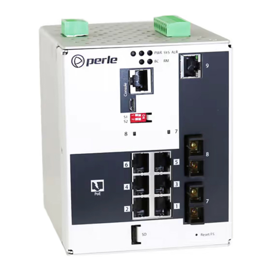
11 – 100Base-X Fiber ports 5 – DIP switches 12 – Fiber status 6 – 10/100/1000Base-T Ethernet Port 13 - Wall Mount Bracket Screw Holes 7 – 10/100/1000Base-T Ethernet Ports 14 - DIN Rail Clip with PoE/PoE+ capability IDS-509FPP Hardware Installation Guide... - Page 7 9 – Terminal Block for Digital Inputs/Relays 4 – Console Port – USB 10 – Reset/FS 5 – DIP switches 11 – Fiber status 6 – 100Base-X Fiber port 12 - Wall Mount Bracket Screw Holes 13 - DIN Rail Clip IDS-509FPP Hardware Installation Guide...
-
Page 8: Led Indicators
State Description No alarms configured Green - solid Alarms configured, but no alarms detected Red-solid Alarm condition detected Red blinking Alarm condition detected and Alarm Relay activated BC (Backup Coupling) State Description Backup Coupling not enabled IDS-509FPP Hardware Installation Guide... - Page 9 Green - flashing Ring Master unable to establish a ring due to missing link on one of the Ring ports Yellow -solid Ring Master Active, redundant port unblocked - indicates a break in the Ring IDS-509FPP Hardware Installation Guide...
-
Page 10: Ports
Digital Input Connector Two Digital Inputs are provided that can be used for the generation of alarms (SNMP trap, energizing of on board Alarm Relay etc.). IDS-509FPP Hardware Installation Guide... -
Page 11: Port Status Indicators
10 Mbps On solid Port Link Random blinking Port Link and Activity Slow blinking Error disabled Rapid blinking Port in Fast Setup Mode Fiber Port Status Indicators Port Link State Description Green Link Green Flashing Link/Activity IDS-509FPP Hardware Installation Guide... -
Page 12: Terminal Block Connectors
P2 - Power Input 2 IN 1 - Digital Input 1 - Dry Contact IN 2 - Digital Input 2 - Wet Contact R - Relay with 2 connection points - Normally Open (NO) / Normally Closed (NC) IDS-509FPP Hardware Installation Guide... -
Page 13: Dip Switches
Port Assignment Ring Ports 1, 2 Coupling Port Note: DIP switches are read during system boot up. If a DIP switch is changed the IDS switch must be rebooted in order for the change to take effect. IDS-509FPP Hardware Installation Guide... -
Page 14: Installation
Limited power means complying with one of the following requirements. Class 2 circuit according to Canadian Electrical Code, Part 1, C22.1 Class 2 circuit according to National Electrical Code, NFPA-70 Limited Power Supply (LPS) according to EN/IEC 60950-1; IDS-509FPP Hardware Installation Guide... -
Page 15: Terminal Block Connectors
Warning: In case of malfunction or damage, no attempts at repair should be made. Do not dismantle the product. All repairs need to be made by a qualified Perle representative. Warning: Explosion hazard. Do not remove or replace any ports, connectors, memory cards, lamps, fuses plug-in modules (as applicable) or operate unless power has been disconnected or the area is free of ignitable concentrations. -
Page 16: Wiring The Relay Alarm
5. Re-insert the Terminal block connector if removed. 6. Turn on power source. Terminal Block Connectors. Warning: Ensure power has been removed at the source of the alarm circuit prior to pro- ceeding with connections to the alarm relay. IDS-509FPP Hardware Installation Guide... -
Page 17: Connecting The Console Port
Enter to display the setup prompt. Warning: If you connect or disconnect the console cable with the power applied to the switch or any device on the network, an electrical arc can occur. This could cause an IDS-509FPP Hardware Installation Guide... - Page 18 This could cause an explosion when installed in a hazardous location. Ensure the power is removed from all devices prior to making the cable connection. IDS-509FPP Hardware Installation Guide...
-
Page 19: Connecting Data Ports
Resetting the Switch The Reset/Fast Setup button is located near the bottom of the switch. A small tool such as a paper clip is needed to access the recessed button. IDS-509FPP Hardware Installation Guide... - Page 20 The LEDs will behave according to the table below. Behavior Yellow during the booting process. Once the system software has been loaded, the PWR LED will reflect the status of the power inputs. Green blinking - Boot process underway. IDS-509FPP Hardware Installation Guide...
- Page 21 When the switch is not in factory default, the "Fast Setup Mode" sequence will activate Password recovery. Note: The password recovery feature can be disabled in the software. Behavior On solid - during reset process Off - to indicate that reset has completed IDS-509FPP Hardware Installation Guide...
-
Page 22: Configuring The Ids Switch
Web Device Manager The Perle Web Device Manager is an embedded Web based application that provides an easy to use browser interface for managing the switch. This interface provides the ability to configure and manage the switch. This is accessible through any standard desktop web browser. -
Page 23: Appendix A - Technical Specifications
Appendix A - Technical Specifications This appendix provides the technical specification for the IDS-509FPP(-XT) switches. Technical Specifications Power Power Connector • 4-Pin Removable Terminal Block • Grounding screw on metal chassis • Dual Power Input Dual Power Input • 54 VDC nominal 50-57 VDC (Poe+ IEEE 802.3at type 2), 5.5A Max... - Page 24 -25° C to 70° C (-13° F to 158° F) IDS-509FPP-XT -40° C to 85° C (-40° F to 185° F) Operating Humidity Range 5% to 90% non-condensing Storage Humidity Range 5% to 90% non-condensing Operating Altitude Up to 3,048 meters (10,000 feet) IDS-509FPP Hardware Installation Guide...
- Page 25 Class 1 Laser safety requirements for those models with fixed fiber transceiver modules EN 60825-1:2007 FDA/CDRH 21 CFR1040.10 and 21 CFR1040.11 Hazardous Locations (Hazloc) ANSI/ISA 12.12.01, Class 1 Division 2 Groups A-D ATEX Class I Zone 2 IDS-509FPP Hardware Installation Guide...
- Page 26 Contact information for the Perle Technical Assistance Center (PTAC) can be found at the link below. www.perle.com/support_services/support_request.shtml Warranty / Registration This product is covered by the Perle Ethernet Switches Warranty. Details can be found at: https://www.perle.com/support_services/warranty.shtml IDS-509FPP Hardware Installation Guide...
-
Page 27: Appendix B - Sample Labels
Appendix B - Sample Labels IDS-509FPP Hardware Installation Guide... -
Page 28: Appendix C - Mechanical Drawings
Appendix C - Mechanical Drawings IDS-509FPP Hardware Installation Guide... - Page 29 IDS-509FPP Hardware Installation Guide...
-
Page 30: Appendix D - Din Rail And Wall Mounting
If you have purchased the optional wall mounting kit then proceed as below: 1. Remove the DIN rail clip from the rear panel on the IDS switch. 2. Attach the wall mount plates to the IDS switch as shown below using the screws provided in the kit. IDS-509FPP Hardware Installation Guide... - Page 31 6. Pull the IDS switch down to lock the IDS switch to the wall mount. 7. Tighten the four screws securely to the wall. Note: for best results use screws with the following attributes Head diameter .5 - .6 mm Shaft diameter 3 -3.5 mm IDS-509FPP Hardware Installation Guide...
-
Page 32: Appendix E - Ids Maintenance
Do not use solvents or cleaning agents on this unit • Keep vent holes clear of debris • If case gets dirty wipe with a dry cloth • Ensure all cables are in good working condition • Replace any frayed cables or cables without clips IDS-509FPP Hardware Installation Guide... -
Page 33: Appendix F - Cables And Connectors
Straight through or Ethernet Crossover cable Note: An optional cable adapter is available to provide RJ45 to DB9 conversion: Perle’s optional RJ45 to DB9-F cross- over adapter model DB0020C enables a straight through Ethernet cable to connect the RJ45 console port to a PC serial port. - Page 34 Multimode 50/125 or 62.5/125 micron fiber cable Single mode 9/125 micron fiber cable Simplex (BIDI, single strand) SC or ST connector Multimode 50/125 or 62.5/125 micron fiber cable Single mode 9/125 micron fiber cable Ethnernet Connector - 8-pin RJ-45 Fiber Connections IDS-509FPP Hardware Installation Guide...
- Page 35 For PoE devices up to 15.4 watts per port • For PoE+ devices up to 30 watts per port Connect the copper cables from each TP port(RJ45) on the IDS-509PP switch to compliant Powered Devices (PDs). See below for RJ-45 pinouts for PoE/PoE+ ports. IDS-509FPP Hardware Installation Guide...
Need help?
Do you have a question about the IDS-509FPP and is the answer not in the manual?
Questions and answers