
Related Manuals for Perle IDS-509C


Summary of Contents for Perle IDS-509C
- Page 1 IDS-509C Hardware Installation Guide Managed Industrial Ethernet Switches Updated: October 2016 Revision 1.10 www.perle.com Document Part#:5500385-10...
- Page 2 Modifications to this product not authorized by Perle could void the FCC approval and negate your authority to operate the product. Perle reserves the right to make changes without further notice, to any products to improve reliability, function, or design.
-
Page 3: Table Of Contents
Table of Contents Preface ......................2 Overview . -
Page 4: Preface
Preface Audience This guide is for the network or computer technician responsible for installing Perle IDS series switches. Familiarity with the concepts and terminology of Ethernet and local area networks is required. Purpose This document describes the hardware and physical characteristics of the Perle IDS switch. -
Page 5: Overview
The table below gives a brief overview of the models covered in this guide. For more details and for the most up-to-date list of models, please refer to the product pages at www.perle.com. 10/100/1000Base-T Combo Standard Models Temp Ports Ports IDS-509C Standard IDS-509C-XT Industrial IDS-509C Hardware Installation Guide... -
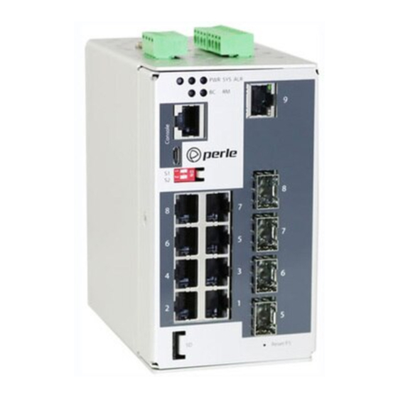
Page 6: Switch Models Views
9 – Terminal Block – Relay, I/O 4 – Console Port – USB 10 - Reset / FS (Fast Setup) 5 – DIP switches 11 -Wall Mount Bracket Screw Holes 6 – Ethernet/Fiber Combo Ports 12 - DIN Rail Clip IDS-509C Hardware Installation Guide... -
Page 7: Led Indicators
Alarms configured, but no alarms detected Alarm condition detected Red - solid Red - blinking Alarm condition detected and Alarm Relay activated BC (Backup Coupling) State Description Backup Coupling not enabled Green - solid Backup Coupling Link enabled IDS-509C Hardware Installation Guide... - Page 8 Green - flashing Ring Master unable to establish a ring due to missing link on one of the Ring ports Yellow - solid Ring Master Active, redundant port unblocked - indi- cates a break in the Ring IDS-509C Hardware Installation Guide...
-
Page 9: Ports
(Ethernet and SFP module), the SFP module will take priority 100/1000 Mb/s SFP Slots The SFP slots can accommodate industry standard SFP’s from Perle or other suppliers. These SFP’s can be 100 or 1000 Mb/s or can be SGMII models including 1000Base-T Copper SFP’s. -
Page 10: Port Status Indicators
Random blinking Port Link and Activity Slow blinking Error disabled Rapid blinking Port in Fast Setup Mode SFP Status Indicators Located on the associated Ethernet port connector Port Link State Description Green Link Link/Activity Green Flashing IDS-509C Hardware Installation Guide... -
Page 11: Terminal Block Connectors
P2 - Power Input 2 IN 1 - Digital Input 1 - Dry Contact IN 2 - Digital Input 2 - Wet Contact R - Relay with 2 connection points - Normally Open (NO) / Normally Closed (NC) IDS-509C Hardware Installation Guide... -
Page 12: Dip Switches
Coupling: Backup on Port 4 (Note 1) Client Primary Ring Feature: enabled Ring Role: Client Coupling: none Note 1: If the backup coupling feature is not used, then port 4 can be used as a normal connection port. IDS-509C Hardware Installation Guide... - Page 13 Port Assignment Ring Ports 1, 2 Coupling Port Note: DIP switches are read during system boot up. If a DIP switch is changed the IDS switch must be rebooted in order for the change to take effect. IDS-509C Hardware Installation Guide...
-
Page 14: Installation
Ensure that voltage and current supplied by the alarm circuits are within the stated Alarm Relay specifications. Warning: In hazardous location installations, failure to remove from the source prior to completing the wiring connections to the alarm relay could cause an electrical arc resulting in a possible explosion. IDS-509C Hardware Installation Guide... -
Page 15: Terminal Block-Power Connectors
Warning: In case of malfunction or damage, no attempts at repair should be made. Do not dismantle the product. All repairs need to be made by a qualified Perle representative. Warning: Explosion hazard. Do not remove or replace lamps, fuses or plug-in modules (as applicable) unless power has been disconnected or the area is free of ignitable concentrations. -
Page 16: Wiring The Relay Alarm
Alarm Relay specifications. Warning: In hazardous location installations, failure to remove the power from the source prior to completing the wiring connections to the alarm relay could cause an electrical arc resulting in a possible explosion. IDS-509C Hardware Installation Guide... -
Page 17: Wiring Digital Inputs
Digital Input specifications. Warning: In hazardous location installations, failure to remove the power from the source prior to completing the wiring connections to the alarm relay could cause an electrical arc resulting in a possible explosion. IDS-509C Hardware Installation Guide... -
Page 18: Connecting The Console Port
This could cause an explosion when installed in a hazardous location. Ensure the power is removed from all devices prior to making the cable connection. IDS-509C Hardware Installation Guide... - Page 19 This could cause an explosion when installed in a hazardous location. Ensure the power is removed from all devices prior to making the cable connection. IDS-509C Hardware Installation Guide...
-
Page 20: Connecting Data Ports
SFP module in. SFP modules are keyed so you can only insert them one way. 3. If the SFP module is equipped with a clasp, ensure the clasp is in the locked position. 4. The appropriate fiber cable can now be connected to the SFP module. IDS-509C Hardware Installation Guide... - Page 21 SFP modules from their slots could cause an electrical arc resulting in a possible explosion. Note: Changing the SFP to one that operates at a different speed (ex. 1000Mbps to 100Mbps) will require a reboot of the switch. IDS-509C Hardware Installation Guide...
-
Page 22: Resetting The Switch
Reset to Factory Default Configuration The switch can be reset to the Factory default configuration. When this is done, all config- uration, user IDs, passwords and security certificates are deleted. The start-up and backup software are unaffected. Follow this procedure: IDS-509C Hardware Installation Guide... - Page 23 Rapid blinking on the first available RJ- / Speed 45 port to which the PC can be connected. Password Recovery When the switch is not in factory default, the "Fast Setup Mode" sequence will activate Password recovery. IDS-509C Hardware Installation Guide...
-
Page 24: Configuring The Ids Switch
Web Device Manager The Perle Web Device Manager is an embedded Web based application that provides an easy to use browser interface for managing the switch. This interface provides the ability to configure and manage the switch. This is accessible through any standard desktop web browser. -
Page 25: Appendix A - Technical Specifications
• Ethernet isolation 1500 V SFP Slots • 100/1000Base-X MSA compliant SFP’s • Also supports SGMII SFP’s Console port • RJ45 DTE - serial port • MicroUSB Type B female port - serial interface Switch properties IDS-509C Hardware Installation Guide... - Page 26 IEC/EN 61000-4-4 (EFT) IEC/EN 61000-4-5 (Surge) IEC/EN 61000-4-6 (CS) IEC/EN 61000-4-8 (Magnetic Field) IEC/EN 61000-6-2 (General Immunity in Industrial Environments) Hazardous Locations (Hazloc) ANSI/ISA 12.12.01, Class 1 Division 2 Groups A-D* ATEX Zone 2 * * pending IDS-509C Hardware Installation Guide...
- Page 27 Contact information for the Perle Technical Assistance Center (PTAC) can be found at the link below. www.perle.com/support_services/support_request.shtml Warranty / Registration This product is covered by the Perle Ethernet Switches Warranty. Details can be found at: https://www.perle.com/support_services/warranty.shtml IDS-509C Hardware Installation Guide...
-
Page 28: Appendix B - Sample Labels
Appendix B - Sample Labels Appendix B - Sample Labels IDS-509C Hardware Installation Guide... -
Page 29: Appendix C - Mechanical Drawings
Appendix C - Mechanical Drawings Appendix C - Mechanical Drawings IDS-509C Hardware Installation Guide... -
Page 30: Appendix D - Din Rail And Wall Mounting
2. Insert a flat blade screwdriver into the slot and twist the base to release the clip. Alter- natively a downward force on the clip will release the clip. 3. When the clip is released, pull the bottom of the switch out slightly and remove the switch from the DIN rail. IDS-509C Hardware Installation Guide... - Page 31 6. Pull the IDS switch down to lock the IDS switch to the wall mount. 7. Tighten the four screws securely to the wall. Note: for best results use screws with the following attributes Head diameter .5 - .6 mm Shaft diameter 3 -3.5 mm IDS-509C Hardware Installation Guide...
-
Page 32: Appendix E - Ids Maintenance
Do not use solvents or cleaning agents on this unit • Keep vent holes clear of debris • If case gets dirty wipe with a dry cloth • Ensure all cables are in good working condition • Replace any frayed cables or cables without clips IDS-509C Hardware Installation Guide... -
Page 33: Appendix F - Cables And Connectors
Ethernet cable used (straight-through or cross-over), and the type of device (NIC-type or HUB/Switch-type) connected to the port. Requirements: • Cat 5 UTP or STP, Cat 5e cables • 24-22 AWG (0.20mm - 0.33mm • Straight through or Ethernet Crossover cable IDS-509C Hardware Installation Guide... - Page 34 Appendix F - Cables and Connectors Note: An optional cable adapter is available to provide RJ45 to DB9 conversion: Perle’s optional RJ45 to DB9-F crossover adapter model DB0020C enables a straight through Ethernet cable to connect the RJ45 console port to a PC serial port.
Need help?
Do you have a question about the IDS-509C and is the answer not in the manual?
Questions and answers