
Subscribe to Our Youtube Channel
Related Manuals for Perle IDS-509G2 Series


Summary of Contents for Perle IDS-509G2 Series
- Page 1 IDS-509G Hardware Installation Guide Managed Industrial Ethernet Switches Updated: October 2016 Revision 1.10 www.perle.com Document Part#:5500384-10...
- Page 2 Modifications to this product not authorized by Perle could void the FCC approval and negate your authority to operate the product. Perle reserves the right to make changes without further notice, to any products to improve reliability, function, or design.
-
Page 3: Table Of Contents
Table of Contents Preface ......................2 Overview . -
Page 4: Preface
Preface Audience This guide is for the network or computer technician responsible for installing Perle IDS series switches. Familiarity with the concepts and terminology of Ethernet and local area networks is required. Purpose This document describes the hardware and physical characteristics of the Perle IDS switch. -
Page 5: Overview
Port Status Indicators The table below gives a brief overview of the models covered in this guide. For more details and for the most up-to-date list of models, please refer to the product pages at www.perle.com. 10/100/1000Base-T Fiber Standard Models... -
Page 6: Switch Models Views
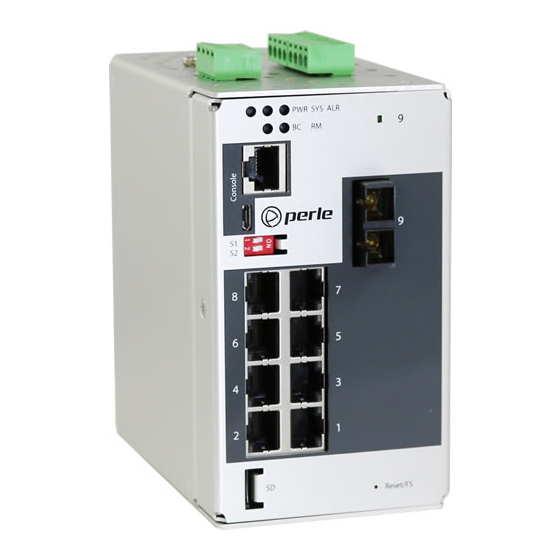
Overview Switch Models Views IDS-509G-xxxxxxx IDS-509G-xxxxxxx-XT 1 – Terminal Block for Power 1, 2 8 – Terminal Block – Relay, I/O 2 – Status LEDs 9 – Fiber Status LED 3 – Console Port – serial 10 - 1000Base-X Fiber port 4 –... - Page 7 Overview IDS-509G2-xxxxxxx IDS-509G2-xxxxxxx-XT 1 – Terminal Block for Power 1, 2 8 - SD Card Slot 2 – Status LEDs 9 – Terminal Block – Relay, I/O 3 – Console Port – serial 10 – 10/100/1000 Base-T Port 4 – Console Port – USB 11 - 1000Base-X Fiber Ports 5 –...
- Page 8 Overview IDS-509G3-xxxxxxx IDS-509G3-xxxxxxx-XT 1 – Terminal Block for Power 1, 2 8 - SD Card Slot 2 – Status LEDs 9 – Terminal Block – Relay, I/O 3 – Console Port – serial 10 - Fiber Port Status LED 4 – Console Port – USB 11 - 1000Base-X Fiber Port 5 –...
-
Page 9: Led Indicators
Overview LED Indicators P (Power Inputs) State Description Green P1 and P2 Power inputs within specifications Yellow P1 or P2 Providing power within specifications Neither P1 or P2 providing power within specifications Sys (System Status) State Description Green - blinking (after power on) System booting System ready/operating normally Green - solid... - Page 10 Overview RM (Ring Master) State Description Ring Master not activated Green - solid Ring Master Active, redundant port blocked. Coupling Link enabled Green - flashing Ring Master unable to establish a ring due to missing link on one of the Ring ports Yellow - solid Ring Master Active, redundant port unblocked - indi- cates a break in the Ring...
-
Page 11: Ports
SC or ST connectors are available as well as single mode, multi mode, duplex and simple models. Consult the full model list at www.perle.com RJ-45 Console Port This is a console management port providing access to the switch management function using the industry standard CLI command set. -
Page 12: Port Status Indicators
Overview Port Status Indicators Ethernet Port Status Indicators Port Link / Speed (Green and Yellow LEDs) State Description Green 1000 Mbps Green / Yellow 100 Mbps Yellow 10 Mbps On solid Port Link Random blinking Port Link and Activity Slow blinking Error disabled Rapid blinking Port in Fast Setup Mode... -
Page 13: Terminal Block Connectors
Overview Terminal Block Connectors P1 - Power Input 1 P2 - Power Input 2 IN 1 - Digital Input 1 - Dry Contact IN 2 - Digital Input 2 - Wet Contact R - Relay with 2 connection points - Normally Open (NO) / Normally Closed (NC) IDS-509G Hardware Installation Guide... -
Page 14: Dip Switches
Overview DIP Switches The DIP switches on the IDS switch provide a quick and easy way to setup a Ring in order to achieve improved network reliability and faster recovery times from network faults. A Ring can also be setup and configured from any of the software configuration methods. Software configuration methods provide access to additional parameters as well as the more advanced Ring features. - Page 15 Overview Port Assignment Ring Ports 1, 2 Coupling Port Note: DIP switches are read during system boot up. If a DIP switch is changed the IDS switch must be rebooted in order for the change to take effect. IDS-509G Hardware Installation Guide...
-
Page 16: Installation
Installation Installation This chapter discusses the following topics: • Cautions and Warnings • Terminal Block-Power Connectors • Grounding the IDS Switch • Connecting Power to the IDS Switch • Wiring the Relay Alarm • Connecting the Console Port • RJ45 Console Port •... -
Page 17: Terminal Block-Power Connectors
Warning: In case of malfunction or damage, no attempts at repair should be made. Do not dismantle the product. All repairs need to be made by a qualified Perle representative. Warning: Explosion hazard. Do not remove or replace lamps, fuses or plug-in modules (as applicable) unless power has been disconnected or the area is free of ignitable concentrations. -
Page 18: Wiring The Relay Alarm
Installation 6. Connect P2 (power source 2, beginning at Step 1) 7. Ensure that there is one individual conductor for each clamping point. Wiring the Relay Alarm The IDS switch has a relay with a Normally Closed (NC) terminal pair as well as a Nor- mally Open (NO) one. -
Page 19: Wiring Digital Inputs
Installation Wiring Digital Inputs The IDS switch has two digital input connections, one to sense to Dry Contact and one to sense a Wet Contact. IN1: This can sense a dry contact. On this terminal pair the IDS switch provides a voltage and current and can monitor the opening can closing of a dry contact switch. -
Page 20: Connecting The Console Port
Installation Connecting the Console Port The IDS switch can be fully configured and managed from the console port. The console ports provide direct access to the Command Line Interface (CLI). The MicroUSB console port has priority on a reboot of the switch and will be activated first. If no USB console port session is detected then the RJ45 console port will then be activated. - Page 21 Installation MicroUSB Console Port 1. Connect a USB cable to the PC’s USB port, then connect the other end of the cable to the IDS switch’s micro-B USB connector. 2. Connect power to the switch as described in <Color><BoldItalic>Connecting Power to the IDS Switch 3.
-
Page 22: Connecting Data Ports
Installation Connecting Data Ports Ethernet Connections By default all of the 10/100/1000 ports will automatically set themselves up to match the speeds of all attached devices. If auto negotiation is not supported by one or more attached devices, the ports can be configured to operate at fixed speeds and duplex settings. Warning: In hazardous location installations, failure to remove the power from the source prior when completing the wiring connections to the Ethernet ports could cause an electri-... -
Page 23: Resetting The Switch
Installation Resetting the Switch The Reset/Fast Setup button is located near the bottom of the switch. A small tool such as a paper clip is needed to access the recessed button. Soft Reset To reset/restart the switch you can perform a soft reset. Press and immediately release the reset button to perform a soft reset. - Page 24 Installation • Power off the switch • Press and hold the reset button • While continuing to hold the reset button, apply power to the switch • ALR LED will go on after power up; when it goes out; release the reset button The switch is now reset to factory default configuration.
-
Page 25: Configuring The Ids Switch
Web Device Manager The Perle Web Device Manager is an embedded Web based application that provides an easy to use browser interface for managing the switch. This interface provides the ability to configure and manage the switch. This is accessible through any standard desktop web browser. -
Page 26: Appendix A - Technical Specifications
Appendix A - Technical Specifications Appendix A - Technical Specifications Technical Specifications Power Power Connector • 4-Pin Removable Terminal Block • Grounding screw on metal chassis • Dual Power Input Input Voltage • 12/24/48 VDC Nominal(9.6 to 60 VDC) - 2.0A Max •... - Page 27 Appendix A - Technical Specifications Technical Specifications Standards IEEE 802.3 for 10Base-T IEEE 802.3u for 100Base-TX IEEE 802.3ab for 1000Base-T IEEE 802.3x for Flow Control Environmental Specifications Operating Temperature Ranges IDS-509G -10° C to 60° C (14° F to 140° F). IDS-509G-XT -40°...
- Page 28 Contact information for the Perle Technical Assistance Center (PTAC) can be found at the link below. www.perle.com/support_services/support_request.shtml Warranty / Registration This product is covered by the Perle Ethernet Switches Warranty. Details can be found at: https://www.perle.com/support_services/warranty.shtml IDS-509G Hardware Installation Guide...
-
Page 29: Appendix B - Sample Labels
Appendix B - Sample Labels Appendix B - Sample Labels IDS-509G Hardware Installation Guide... -
Page 30: Appendix C - Mechanical Drawings
Appendix C - Mechanical Drawings Appendix C - Mechanical Drawings IDS-509G Hardware Installation Guide... - Page 31 Appendix C - Mechanical Drawings IDS-509G Hardware Installation Guide...
- Page 32 Appendix C - Mechanical Drawings IDS-509G Hardware Installation Guide...
-
Page 33: Appendix D - Din Rail And Wall Mounting
Appendix D - DIN Rail and Wall Mounting Appendix D - DIN Rail and Wall Mounting This appendix provides instruction on the following: • Mounting the IDS Switch on a DIN Rail • Removing the IDS from the DIN Rail •... - Page 34 Appendix D - DIN Rail and Wall Mounting Wall Mounting the IDS If you have purchased the optional wall mounting kit then proceed as below: 1. Remove the DIN rail clip from the rear panel on the IDS switch. 2. Attach the wall mount plates to the IDS switch as shown below using the screws pro- vided in the kit.
-
Page 35: Appendix E - Ids Maintenance
Appendix E - IDS Maintenance Appendix E - IDS Maintenance • Ensure there is clearance of 50.8mm (2 inches) on all sides of the IDS switch to pro- vide proper airflow through the unit • Do not use solvents or cleaning agents on this unit •... -
Page 36: Appendix F - Cables And Connectors
Appendix F - Cables and Connectors Appendix F - Cables and Connectors This appendix discusses the following topics: • RJ45-Console Port Pinouts: • Ethernet cables • Ethernet Connector - 8 pin RJ45 • Fiber Port Cabling Requirements RJ45-Console Port Pinouts The console port uses a shield cable with an 8-pin female connector (with DTE pinouts). - Page 37 Appendix F - Cables and Connectors Note: An optional cable adapter is available to provide RJ45 to DB9 conversion: Perle’s optional RJ45 to DB9-F crossover adapter model DB0020C enables a straight through Ethernet cable to connect the RJ45 console port to a PC serial port.
Need help?
Do you have a question about the IDS-509G2 Series and is the answer not in the manual?
Questions and answers