
Related Manuals for Generac Power Systems MMG480DI4


Summary of Contents for Generac Power Systems MMG480DI4
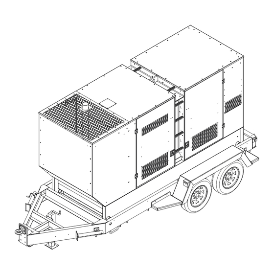
- Page 1 DIESEL GENERATOR MMG330DI4 • MMG480DI4 OPERATING MANUAL Parts manuals available online at www.generacmobile.com 33797 C 07/16...
- Page 2 WARNING CALIFORNIA PROPOSITION 65 WARNING: Diesel engine exhaust and some of its constituents are known to the state of California to cause cancer, birth defects, and other reproductive harm. (000004) WARNING CALIFORNIA PROPOSITION 65 WARNING: This product contains or emits chemicals known to the state of California to cause cancer, birth defects, and other reproductive harm.
- Page 3 Introduction This manual provides information and procedures to safely operate and maintain the Generac Mobile Products unit. For your own safety and protection from physical injury, carefully read, understand, and observe the safety instructions described in this manual. Keep a copy of this manual with the unit at all times. Additional copies are available from Generac Mobile Products, or can be found at www.generacmobile.com.The information contained in this manual was based on machines in production at the time of publication.
- Page 4 This Page Intentionally Left Blank...
-
Page 5: Table Of Contents
Unit Dimensions ........................7 Unit Serial Number Locations......................8 Component Locations (MMG330 Shown) ..................9 Control Panel - MMG330DI4 ......................10 Control Panel - MMG480DI4 ......................11 Power Zone™ Controller ........................12 Controller Features and Functions ....................12 Operator Screens ........................ 12 Alarm Mute .......................... - Page 6 Section 5 - Troubleshooting Section 6 - Wiring Diagrams AC Wiring - MMG330DI4........................45 AC Wiring - MMG480DI4........................46 AC Wiring - 4 Position Voltage Selector Switch Option (MMG330DI4 only) ........47 AC Wiring Diagrams for Optional Equipment ................... 48 DC Wiring Diagram...........................
-
Page 7: Section 1 - Safety
Section 1 - Safety SAFETY NOTES This is the safety alert symbol. It is used to alert you to potential personal injury hazards. Obey all safety messages that follow this symbol to avoid possible injury or death. This manual contains DANGERS, WARNINGS, CAUTIONS, NOTICES and NOTES which must be followed to prevent the possibility of improper service, damage to the equipment, personal injury or death. -
Page 8: Engine Safety
Safety ENGINE SAFETY Internal combustion engines present special hazards during operation and fueling. Failure to follow the safety guidelines described below could result in severe injury or death. Read and follow all safety warnings described in the engine operator's manual. A copy of this manual was supplied with the unit when it was shipped from the factory. -
Page 9: Reporting Trailer Safety Defects
Safety • When towing, maintain extra space between vehicles and avoid soft shoulders, curbs and sudden lane changes. Practice turning, stopping and backing up in an area away from heavy traffic prior to transporting the unit. • Wipe the coupler clean and apply fresh grease each time the trailer is towed to eliminate squeaking. REPORTING TRAILER SAFETY DEFECTS If you believe your trailer has a defect which could cause a crash or could cause injury or death, you should immediately inform the National Highway Traffic Safety Administration (NHTSA) in addition to notifying Generac Mobile Products... -
Page 10: Safety Symbol Summary
Safety SAFETY SYMBOL SUMMARY The safety and operating decals affixed to the unit provide important instructions and warn of dangers and hazards. Replace any missing or hard-to-read decals and use care when washing or cleaning the unit. Decal placement and part numbers can be found in the online parts manual at www.generacmobile.com. -
Page 11: Section 2 - General Information
Section 2 - General Information SPECIFICATIONS GENERAC MODEL MMG330DI4 MMG330DI4 Super Start Engine Make/Brand..............John Deere ........John Deere Model ................PE609HFG95....... PE609HFG95 Horsepower - prime hp (kW) .......... 396 (295)........396 (295) Horsepower - standby hp (kW) ........440 (328)........440 (328) Operating Speed rpm ............. - Page 12 General Information GENERAC MODEL MMG480DI4 Engine Make/Brand..........................John Deere Model ............................. RG6135HFG95 Horsepower - prime hp (kW) ....................571 (426) Horsepower - standby hp (kW) ..................... 634 (472) Operating Speed rpm ......................1800 Displacement in (L) ......................824 (13.5) Cylinders - qty ........................6 Fuel Consumption - 100% prime gph (Lph) .................
-
Page 13: Unit Dimensions
General Information Unit Dimensions Figure 2-1. Unit Dimensions Skid Mounted 171 in (4.35 m) 60 in (1.52 m) 90 in (2.29 m) MGG330 Trailer Mounted 230 in (5.84 m) 102 in (2.59 m) 110 in (2.79 m) Skid Mounted 175 in (4.45 m) 60 in (1.52 m) 96 in (2.44 m) MGG480... -
Page 14: Unit Serial Number Locations
A wholly owned subsidiary of TIRE AND LOADING INFORMATION MANUFACTURED BY/FABRIQUE PAR: Generac Mobile Products LLC DATE: 00/0000 Generac Power Systems, Inc. GVWR/PNBV: 000KG (0000LBS) COLD INF. PRESS./ RENSEIGNEMENTS SUR LES 215 Power Drive • Berlin, WI 54923 PRESS. DE... -
Page 15: Component Locations (Mmg330 Shown)
General Information COMPONENT LOCATIONS (MMG330 SHOWN) *MMG480 control panel is accessible from the rear side of the unit. Figure 2-3. Component Locations Engine access Reconnect board access Central lift point Emergency stop Ladder Control panel access Generator Access Engine exhaust Radiator drain port Radiator access panel Oil drain port... -
Page 16: Control Panel - Mmg330Di4
General Information CONTROL PANEL - MMG330DI4 Figure 2-4. Control Panel Component Locations Document holder 120/240V twist-lock receptacles (3) Power Zone™ controller Connection for engine block heater (optional) 120V GFCI duplex receptacles (2) Door safety switch 50A circuit breakers (3) Output ground connection 20A circuit breakers (2) Connection terminal lugs Remote start terminal block... -
Page 17: Control Panel - Mmg480Di4
General Information CONTROL PANEL - MMG480DI4 Figure 2-5. Control Panel Component Locations Main circuit breaker for connection lugs Cam lock connectors (20) (optional) Diesel exhaust filter cleaning switch Connection for battery charger (optional) Power Zone™ controller Connection for engine block heater (optional) -
Page 18: Power Zone™ Controller
General Information POWER ZONE™ CONTROLLER The Power Zone™ controller is an auto start controller that monitors the unit and indicates operational status and fault conditions. The controller can be programmed to automatically start or stop on based time schedule, fault condition, or load demand. -
Page 19: Navigation Buttons
General Information Navigation Buttons These buttons are used to navigate and interact with the Power Zone™ controller screens. Pressing any directional arrow (“▲”, “►”, “▼”, “◄”) while on any of the operator screens will open the maintenance screens, and navigate the tabs and pages within the maintenance screens. -
Page 20: Engine Screen
General Information Figure 2-7. Home Screen Engine Screen The Engine screen displays the oil pressure, coolant temperature and battery voltage on three main gauges. Below the gauges is an hour gauge displaying the total run time on the engine. This screen also displays maintenance alarm status with the time remaining (black text) or the time past (red text) of scheduled maintenance tasks. -
Page 21: Voltage Adjust Screen
General Information Figure 2-9. Generator Screen Voltage Adjust Screen The Voltage Adjust screen displays the line-to-neutral and line-to-line voltage averages. The operator can electron- ically adjust the voltage within limits to prevent under-voltage or over-voltage conditions using the on-screen instructions. This feature replaces a traditional potentiometer. See Power Zone™... -
Page 22: Generator Summary
General Information Generator Summary The Generator Summary can be found at the top of all maintenance screens and provides an overview of the system. SITE GENSET 8721-A1\8710 20:51 Alternative Config 1 MSC ID. 1 Generator Available Total Total Energy Generator kWh+ 60.0 kVAr... -
Page 23: Alarms Tab
General Information Figure 2-13. Generator Tab Screen Alarms Tab The “Alarms” tab displays warnings, electrical trip and shutdown alarms, and engine Diagnostic Trouble Codes (DTC) that are occurring or have occurred previously. The first page on the “Alarms” tab displays the alarms that are currently active. -
Page 24: Input/Output Tab
General Information The second page of the “Alarms” tab shows the event log with a list of events, including normal operation events and alarm notifications, with the most recent events at the top of the list. All indexed events include the date and time of the event, hours of runtime on the engine when it occurred, along with the event name or alarm type and details. -
Page 25: Status Tab
General Information Status Tab The “Status” tab contains the status and configuration of the controller, firmware and data connections. Figure 2-17. Status Tab Screen GENERATOR MONITORING Generator information is displayed on both the Generator screen and “Generator” tab within the maintenance screens. Generator Screen The Generator screen displays the average voltage frequency, volts and amps from the generator, as well as line- to-line voltage, and individual line-to-neutral voltage, amperage and power (kW). -
Page 26: Generator Tab - Maintenance Screens
General Information Generator Tab - Maintenance Screens Additional generator information can be viewed on the maintenance screens by pressing the left or right arrow and highlighting the “Generator” tab. See Maintenance Screens for more information. ENGINE MONITORING Engine information is displayed on both the Engine screen and “Engine” tab within the maintenance screens. Engine Operator Screen The Engine Operator screen displays the oil pressure, coolant temperature and battery voltage from the engine on the three main gauges. -
Page 27: Diesel Exhaust Filter Monitoring
General Information DIESEL EXHAUST FILTER MONITORING This unit is equipped with a Diesel Particulate Filter (DPF) to meet current EPA emissions standards. This section gives an explanation of the indicators that are displayed on the “DPF Status” screen on the Power Zone™ controller. Diesel particulate filter information can be found on the “Engine”... -
Page 28: Power Zone™ Controller Information Displays, Functions, And Reset
General Information • Alarm: This area will display the Engine Alarm indicator above the words “Alarm - Solid” when an alarm condition occurs. This area displays different text, depending upon which alarm condition occurs. Figure 2-23. Engine Alarm Indicator For more information on the operation of auto exhaust filter regeneration and service regeneration, see Exhaust Filter Cleaning Operations. - Page 29 General Information Remove all 1/2” nuts Link Board Attached in 480 Volt 3Ø Position Link Board Attached in 208 Volt 3Ø Position Figure 2-24. Link Board 33797 C MMG330DI4-480DI4 Operating Manual...
-
Page 30: Control Panel Receptacles
General Information CONTROL PANEL RECEPTACLES The generator is equipped with five receptacles. The 50A Circuit large receptacles are 120/240VAC twist-lock recep- 20A Circuit Breakers tacles rated at 50A each. The smaller receptacles are Breakers 120VAC duplex receptacles rated at 20A each with Ground Fault Circuit Interrupt (GFCI) protection. -
Page 31: Section 3 - Operation
Section 3 - Operation PRE-START CHECKLIST Before starting the generator, carefully read the pre-start checklist. Make sure that all of the items are checked before trying to start the generator. This check list applies to both manual and remote starting of the generator. ... -
Page 32: Automatically Starting The Generator
Operation When the software is loaded, the Home screen will be displayed and the controller will be in “Manual Mode” as indicated at the top of the screen. Stop Mode Time to Empty 15 hr 100 110 Full 3 PHASE 0.0 kW Volts Amps... -
Page 33: Accessing The Configuration Menu
Operation Generators installed in a standby application should be exercised regularly to maintain operating condition and to ensure responsiveness in an emergency situation. Use the following procedures to operate the generator in “Auto Mode”: Accessing the Configuration Menu 1. With the unit stopped, navigate to the maintenance screens by pressing any directional arrow (“▲”, “►”, “▼”, “◄”) from any of the operator screens. -
Page 34: Fine Voltage Adjustment
Operation RUN CABLES THROUGH SLOT Figure 3-3. Connection Lugs DANGER IMPROPER OR INCORRECT CONNECTIONS TO A BUILDING’S ELECTRICAL SYSTEM CAN CAUSE POTENTIALLY LETHAL VOLTAGES TO BACKFEED INTO UTILITY LINES. THIS MAY RESULT IN INJURY OR ELECTROCUTION TO UTILITY WORKERS NEARBY. VERIFY THE GENERATOR IS SUPPLYING POWER TO AN ISOLATED OBJECT OR BUILDING THAT IS NOT CONNECTED TO ANY UTILITY LINES. -
Page 35: Voltage Regulation
Operation Manual Mode Voltage Adjust - Press , voltage will begin flashing - Use arrows to adjust voltage - Press to confirm new voltage. Numbers will stop flashing L-N Average L-L Average 00396 Figure 3-4. Fine Voltage Adjustment 1. With the unit running, press the “Voltage Adjust” screen button. Press the Enter “”... -
Page 36: Exhaust Filter Cleaning Operations
Operation WARNING The main circuit breaker interrupts power to the connection lugs only. The receptacles have power even if the main circuit breaker is “OFF/O”. To disconnect power to the receptacles, use the individual circuit breakers located near each receptacle. EXHAUST FILTER CLEANING OPERATIONS When enabled, the exhaust filter system goes through an automatic cleaning process known as regeneration. -
Page 37: Auto Exercise Timer
Operation DANGER FAILURE TO ISOLATE THE GENERATOR FROM THE NORMAL POWER UTILITY CAN CAUSE POTENTIALLY LETHAL VOLTAGE TO BACKFEED INTO THE UTILITY LINES. THIS MAY RESULT IN INJURY OR ELECTROCUTION OF UTILITY WORKERS NEARBY. VERIFY THE GENERATOR IS ISOLATED BY A TRANSFER SWITCH FROM ANY LOCAL UTILITY LINES. -
Page 38: Schedule Tab
Operation Press the down arrow until “Timer1 ON Time” is selected and press “ENTER.” Adjust the desired time to start running and press “ENTER.” Press the down arrow until “Timer1Duration” is selected and press “ENTER.” Adjust the time period to the length of time the unit should run after starting, and press “ENTER.” Press “PAGE SELECT”... -
Page 39: Set The Unit To Auto Mode
Operation Access the “Scheduler Options” section. Within this section, the scheduler can be enabled, run mode selected, and load mode selected. Item Values Enable Yes/No Run Mode Monthly/Weekly Load Idle, In Island, On Load, Off Load Access the “Scheduler Setup” section. Within this section, each schedule entry can be modified by pressing the Enter “”... -
Page 40: Emergency Stop Switch
Operation EMERGENCY STOP SWITCH The unit is equipped with one Emergency Stop switch. For location of the Emergency Stop switch, see Component Locations (MMG330 Shown). The switch can be accessed and activated with all doors closed and locked. Activate the Emergency Stop switch by pushing the red button in until it locks down. This will trip the main circuit breaker which will open the contact, disconnecting the load to the connection lugs. -
Page 41: Power Zone™ Controller Information Displays, Functions, And Reset
Operation 1. Open the control door and locate the switch labeled “EXHAUST FILTER CLEANING.” Move the switch to “ON / AUTO (I/O)”. Toggle to the “DPF Status” screen on the Power Zone™ controller and verify the Regeneration indicator appears above the words “DPF Lamp” (see Diesel Exhaust Filter Monitoring for information regarding the “DPF Status”... - Page 42 Operation MMG330DI4-480DI4 Operating Manual 33797 C...
-
Page 43: Section 4 - Maintenance
Section 4 - Maintenance EMISSIONS INFORMATION For emissions information, see the OEM engine manual. DAILY WALK AROUND INSPECTION Look for conditions that could hinder performance or safety, such as (but not limited to) oil/coolant/fuel leakage, blocked vents, loose/missing hardware and electrical connections. Visually inspect the fan belt for cracks, fraying, stretching and that the belt is properly seated in the pulley grooves. - Page 44 Maintenance See original equipment manufacturer’s operating manual for a complete list of maintenance requirements. Failure to comply with the procedures as described in the engine operator manual will nullify the warranty, decrease performance and cause equipment damage or premature equipment failure. Maintenance records may be required to complete a warranty request.
-
Page 45: Engine Break-In Requirements
Maintenance Replace primary air cleaner when dust valve restriction indicator gauge shows a vacuum of 25 in. H O or at least every 500 hours. Some operating environments will require more frequent changes. Change the oil and oil filter after the first 100 hours, then every 500 hours. If John Deere Plus-50 II oil or an equivalent is not used, the oil must be changed every 250 hours. -
Page 46: Exhaust Filter Service Requirements
Tighten each of the drive plate bolts to the appropriate specification shown in the table below. Unit ft-lbs (Nm) MMG330DI4 33 (45) MMG480DI4 Install generator fan guard. Reconnect the battery. JACK MAINTENANCE The following procedures should be performed annually. Side-wind models •... -
Page 47: Top-Wind Models
Maintenance standard grease gun on the lubrication point found on the side of the jack near the crank. Rotate the jack handle to distribute the grease evenly. • A lightweight oil must be applied to the handle unit at both sides of the tube. •... - Page 48 Maintenance This Page Intentionally Left Blank MMG330DI4-480DI4 Operating Manual 33797 C...
-
Page 49: Section 5 - Troubleshooting
Section 5 - Troubleshooting WARNING Allow engine to cool before performing any troubleshooting procedures. Contacting the engine when it is hot will cause severe personal injury. Table 2 - Troubleshooting Automatic Shutdown Conditions 1. Check fuel level on the Home screen. Verify generator is sitting level for an accurate reading. - Page 50 Troubleshooting Table 2 - Troubleshooting Automatic Shutdown Conditions 1. Check coolant level in the overflow jug. 2. Restart engine and read the coolant temperature to verify a high coolant temperature shutdown. Stop engine immediately if cool- ant temperature is 230°F (110°C) or more. 3.
-
Page 51: Section 6 - Wiring Diagrams
Section 6 - Wiring Diagrams AC WIRING - MMG330DI4 33797 C MMG330DI4-480DI4 Operating Manual... -
Page 52: Ac Wiring - Mmg480Di4
Wiring Diagrams AC WIRING - MMG480DI4 90494_B_05.20.15 MMG330DI4-480DI4 Operating Manual 33797 C... -
Page 53: Ac Wiring - 4 Position Voltage Selector Switch Option (Mmg330Di4 Only)
Wiring Diagrams AC WIRING - 4 POSITION VOLTAGE SELECTOR SWITCH OPTION (MMG330DI4 ONLY) 90498_A_05.20.15 33797 C MMG330DI4-480DI4 Operating Manual... -
Page 54: Ac Wiring Diagrams For Optional Equipment
Wiring Diagrams AC WIRING DIAGRAMS FOR OPTIONAL EQUIPMENT 90415_T_06.17.15 MMG330DI4-480DI4 Operating Manual 33797 C... -
Page 55: Dc Wiring Diagram
Wiring Diagrams DC WIRING DIAGRAM 90438_I_02.18.16 33797 C MMG330DI4-480DI4 Operating Manual... -
Page 56: Dc Wiring Diagrams For Optional Equipment
Wiring Diagrams DC WIRING DIAGRAMS FOR OPTIONAL EQUIPMENT MMG330DI4-480DI4 Operating Manual 33797 C... -
Page 57: Wiring Block Diagram - Dedicated 12 Lead Generators Option
Wiring Diagrams WIRING BLOCK DIAGRAM - DEDICATED 12 LEAD GENERATORS OPTION 90302_A_11.06.12 33797 C MMG330DI4-480DI4 Operating Manual... -
Page 58: Trailer Wiring Diagram
Wiring Diagrams TRAILER WIRING DIAGRAM 90386_A_02.14.14 MMG330DI4-480DI4 Operating Manual 33797 C... -
Page 59: Wiring Harness - Electric Brake Option
Wiring Diagrams WIRING HARNESS - ELECTRIC BRAKE OPTION 90286_E_03.18.14 33797 C MMG330DI4-480DI4 Operating Manual... - Page 60 Wiring Diagrams This Page Intentionally Left Blank MMG330DI4-480DI4 Operating Manual 33797 C...
-
Page 61: Section 7 - Options & Accessories
Section 7 - Options & Accessories GENERATOR CAM LOCK CONNECTIONS OPTION The generator may be equipped with cam lock connections, located behind the lug door next to the generator output connection lugs. These receptacles provide connection points for attachment of external loads to the generator. A large decal on the inside of the connection lug door details proper connections for selected voltages. -
Page 62: Auxiliary Fuel Tank Option
DO NOT attach L1, L2 and L3 to the left side and Neutral and Ground to the right side. See Control Panel - MMG330DI4 Control Panel - MMG480DI4 for breaker locations. AUXILIARY FUEL TANK OPTION The auxiliary fuel tank option is designed so the unit can run from an external fuel tank. -
Page 63: Fuel Transfer Pump Option
Options & Accessories FUEL TRANSFER PUMP OPTION The fuel transfer pump option allows the fuel tank to be refilled from an external bulk fuel source. When the fuel transfer switch is on and the fuel level drops below 15%, the fuel transfer pump will begin pumping fuel from an external bulk fuel source into the fuel tank on the unit. - Page 64 Options & Accessories This Page Intentionally Left Blank MMG330DI4-480DI4 Operating Manual 33797 C...
- Page 65 Service Log OIL GRADE: _____________________________________ BRAND: __________________________________ COOLANT MIXTURE: _____________________________ BRAND: __________________________________ __________________________________________________________________________________________ __________________________________________________________________________________________ __________________________________________________________________________________________ __________________________________________________________________________________________ __________________________________________________________________________________________ __________________________________________________________________________________________ __________________________________________________________________________________________ __________________________________________________________________________________________ __________________________________________________________________________________________ Hours to Coolant Hours to Coolant Date Oil Level Date Oil Level Service Level Service Level...
- Page 66 Notes ___________________________________________________________________________ ___________________________________________________________________________ ___________________________________________________________________________ ___________________________________________________________________________ ___________________________________________________________________________ ___________________________________________________________________________ ___________________________________________________________________________ ___________________________________________________________________________ ___________________________________________________________________________ ___________________________________________________________________________ ___________________________________________________________________________ ___________________________________________________________________________ ___________________________________________________________________________ ___________________________________________________________________________ ___________________________________________________________________________ ___________________________________________________________________________ ___________________________________________________________________________ ___________________________________________________________________________ ___________________________________________________________________________ ___________________________________________________________________________ ___________________________________________________________________________ ___________________________________________________________________________ ___________________________________________________________________________ ___________________________________________________________________________ ___________________________________________________________________________ ___________________________________________________________________________ ___________________________________________________________________________ ___________________________________________________________________________...
Need help?
Do you have a question about the MMG480DI4 and is the answer not in the manual?
Questions and answers