
Subscribe to Our Youtube Channel
Related Manuals for Generac Power Systems Magnum MGG100M


Summary of Contents for Generac Power Systems Magnum MGG100M
- Page 1 GASEOUS GENERATOR MGG100M 02104 OPERATOR MANUAL Parts manuals available online at www.generacmobileproducts.com 36833 C 11/16...
- Page 2 WARNING California Proposition 65. Engine exhaust and some of its constituents are known to the state of California to cause cancer, birth defects, and other reproductive harm. (000004) WARNING California Proposition 65. This product contains or emits chemicals known to the state of California to cause cancer, birth defects, and other reproductive harm.
- Page 3 Introduction This manual provides information and procedures to safely operate and maintain the Generac Mobile Products unit. For your own safety and protection from physical injury, carefully read, understand, and observe the safety instructions described in this manual. Keep a copy of this manual with the unit at all times. Additional copies are available from Generac Mobile Products LLC, or can be found at www.generacmobileproducts.com.
- Page 4 This Page Intentionally Left Blank 36833 C MGG100M Operating Manual...
-
Page 5: Table Of Contents
Contents Section 1 - Safety Safety Notes ............................1 Operating Safety..........................1 Engine Safety ............................. 2 Electrical Safety..........................2 Battery Safety ............................. 3 Towing Safety............................. 4 Reporting Trailer Safety Defects ....................4 Safety Symbol Summary ........................5 Section 2 - General Information Specifications ............................. - Page 6 Table of Contents Low Fuel Pressure Warning ....................... 22 NG Fuel Filters ........................... 23 Preparing External Drain Ports for Use ................23 Wellhead Priming ..........................23 Unit Alarms and Warnings........................ 23 Non-emissions Alarms ....................... 23 Warnings ..........................23 Non-shutdown Alarms ......................24 Shutdown Alarms ........................
- Page 7 Section 4 - Maintenance Maintenance ............................. 45 General Maintenance Procedure...................... 45 Regular Maintenance Schedule ....................... 46 Maintenance Tasks .......................... 48 Daily Walk Around Inspection ....................48 Engine Oil........................... 48 About the Engine Oil Replenishment System..............48 Checking Engine Oil Level ....................49 Typical Causes of Inaccurate Readings ................
- Page 8 This Page Intentionally Left Blank 36833 C MGG100 Operating Manual viii...
-
Page 9: Section 1 - Safety
Section 1 - Safety SAFETY NOTES This is the safety alert symbol. It is used to alert you to potential personal injury hazards. Obey all safety messages that follow this symbol to avoid possible injury or death. This manual contains DANGERS, WARNINGS, CAUTIONS, NOTICES, and NOTES that must be followed to prevent the possibility of improper service, damage to the equipment, personal injury, or death. -
Page 10: Engine Safety
Safety 5. Engine misfires or there is excessive engine/generator vibration. 6. Protective covers are loose or missing. 7. If the ambient air temperature is above 120°F (49°C). • Make sure slings, chains, hooks, ramps, jacks, and other types of lifting devices are attached securely and have enough weight-bearing capacity to lift or hold the equipment safely. -
Page 11: Battery Safety
Safety BATTERY SAFETY DANGER STORAGE BATTERIES GIVE OFF EXPLOSIVE HYDROGEN GAS. THIS GAS CAN FORM AN EXPLOSIVE MIXTURE AROUND THE BATTERY FOR SEVERAL HOURS AFTER CHARGING. THE SLIGHTEST SPARK CAN IGNITE THE GAS AND CAUSE AN EXPLOSION. AN EXPLOSION CAN SHATTER THE BATTERY AND CAUSE BLIND- NESS OR OTHER INJURY. -
Page 12: Towing Safety
Safety TOWING SAFETY Towing a trailer requires care. Both the trailer and vehicle must be in good condition and securely fastened to each other to reduce the possibility of an accident. Also, some states require that large trailers be registered and licensed. Contact your local Department of Transportation office to check on license requirements for your particular unit. -
Page 13: Safety Symbol Summary
Safety SAFETY SYMBOL SUMMARY This equipment has been supplied with numerous safety and operating decals. These decals provide important operating instructions and warn of dangers and hazards. Replace any missing or hard-to-read decals and use care when washing or cleaning the unit. Below is a summary of the intended meanings for the symbols used on the decals. Safety alert symbol;... - Page 14 Safety This Page Intentionally Left Blank MGG100M Operating Manual 36833 C...
-
Page 15: Section 2 - General Information
Section 2 - General Information SPECIFICATIONS GENERAC MODEL MGG100M Engine Make/Brand........................... Generac Model ............................ G9.0L G18 Type ............................Naturally Aspirated Horsepower, natural gas - prime ................... 80 (60) Operating Speed rpm ......................1800 Displacement in (L) ......................540 (8.9) Cylinders - qty ........................8 Spark plug gap in (mm)...................... -
Page 16: Unit Dimensions
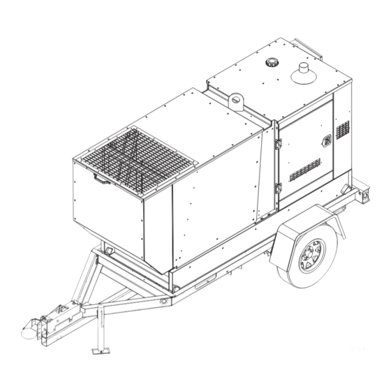
General Information Unit Dimensions Trailer mounted—L H, in. (m) ................168 83 (4.26 1.75 2.1) 00570 Figure 1 - Unit Dimensions Engine Oil Recommendations The engine has been filled with engine oil of a grade recommended by the engine supplier. Use a high quality detergent oil with an appropriate classification and viscosity for the engine type and ambient temperature conditions. -
Page 17: Tag And Label Locations
General Information TAG AND LABEL LOCATIONS Unit ID and VIN Tags Record the information from the unit ID and VIN tags, in case the tags are lost or damaged. When ordering parts or requesting technical assistance, you may be asked to provide this information. VIN Tag TIRE AND LOADING INFORMATION MANUFACTURED BY/FABRIQUE PAR: Generac Mobile Products LLC... -
Page 18: Generator Data Label
General Information Generator Data Label The generator data label is prominently displayed on the generator, behind the NG fuel filters (see Figure Figure 4 - Generator Data Label MGG100M Operating Manual 36833 C... -
Page 19: Component Locations
General Information COMPONENT LOCATIONS Left Side 02228 Figure 5 - Component Locations, Left Side Air filter Manual holder Lift structure Oil filter Oil reservoir Oil fill Catalyst exhaust muffler Coolant jug Fork lift slots 36833 C MGG100M Operating Manual... -
Page 20: Right Side
General Information Right Side 01199 Figure 6 - Component Locations, Right Side Central lift point Oil level controller Coolant pressure cap H-100 controller Coolant drain Main circuit breaker (MLCB) Engine oil drain Customer disconnect switch box Dipstick Connection lugs with cam locks Battery disconnect switch NG inlet port Emergency stop switch... -
Page 21: Fuel System
General Information Fuel System 02203 Figure 7 - MGG100M Fuel System LPV solenoid shut-off valve Primary high pressure regulator Bosch throttle body NG inlet port LPL A/F solenoid valve LPL inlet port LPL solenoid valve vent Moisture separator drain port LPL vaporizer and regulator Particulate filter drain port Wellhead gas A/F solenoid valve... -
Page 22: Equipment Description
General Information EQUIPMENT DESCRIPTION This unit supplies electrical power for operation of compatible electrical loads through the use of a revolving field, alternating current type generator set. Power is delivered by way of connection lugs and 120V customer convenience receptacles. Intended Use This unit is intended to supply direct electrical power to compatible loads, through connections to customer convenience receptacles and connection lugs. -
Page 23: H-100 Control Panel
General Information H-100 CONTROL PANEL The H-100 control panel (Figure 8) enables the operator to start and stop the unit, monitor the unit, and view and respond to alarms and warnings. Components 00621 Figure 8 - H-100 Control Panel Left and right displays Key switch Emergency stop switch ®... -
Page 24: Emergency Stop Switch
General Information Emergency Stop Switch CAUTION Equipment Damage. The emergency stop switch is not to be used to power-down the unit under normal operating circumstances. Doing so will result in equipment damage. (000246) The unit is equipped with two red emergency stop switches, both labeled EMERGENCY STOP. See Figure 6 locations. -
Page 25: Navigation Keypad
General Information Navigation Keypad 02205 Figure 9 - Navigation Keypad The navigation keypad controls the right display. • Arrows: move the cursor around the current screen, enabling selection of menu items. • MENU: immediately displays the Menu page. • HOME: immediately displays the Home page. •... -
Page 26: Engine And Generator Protective Devices
General Information 3. Select field to adjust: Press RIGHT or LEFT, then press ENTER. Note: Applicable fields are HOUR, MINUTE, MONTH, DAY, and YEAR. 4. Change field value: Press UP or DOWN. 5. Save field value: Press ENTER. 6. Repeat steps 3–5, as necessary. ENGINE AND GENERATOR PROTECTIVE DEVICES The generator set might operate for long time periods without an operator present to monitor conditions such as coolant temperature, oil pressure, voltage, and frequency. -
Page 27: Fuse Block
General Information FUSE BLOCK The fuse block is located behind the front panel, in the back lower-left corner of the controller box. The 10A fuse in the F2 slot is the control panel fuse. 00577 Figure 12 - Panel Fuse Block MAIN LINE CIRCUIT BREAKER The main line circuit breaker (MLCB) is below the H-100 control panel (see Figure... -
Page 28: Manual Shut-Off
General Information Manual Shut-Off To manually interrupt power between the generator and connection lugs, use the disconnect lever on the customer disconnect switch box (Figure 13). 02258 Figure 13 - Disconnect Lever EMISSIONS The United States Environmental Protection Agency (US EPA) (and California Air Resources Board (CARB), for engines/equipment certified to California standards) requires that this engine/equipment complies with exhaust and evaporative emissions standards. -
Page 29: Sourcing Natural Gas
General Information Sourcing Natural Gas The unit accepts NG vapor, sourced from either of the following. • A utility supply line • A wellhead Natural gas is drawn into the fuel system through the NG inlet port (see Figure Sourcing Liquid Propane The unit accepts propane liquid, sourced in pressurized tanks. -
Page 30: Genlink Dcp: Dual Fuel Setup And Operation
General Information GenLink DCP: Dual Fuel Setup and Operation The Dual Fuel Setup page in GenLink provides flexibility in controlling the operation of the fuel source switching. There are four modes of operation: default, digital pressure, analog pressure, and digital and analog pressure. The default dual-fuel setup setting is analog. -
Page 31: Ng Fuel Filters
General Information NG Fuel Filters The NG fuel system is equipped with two filters: a moisture separator and particulate filter. Waste material (condensates) exit the filters and then the unit through drain ports. See Figure 7 for filter and drain port locations. CAUTION Condensates may contain aggressive or harmful components. -
Page 32: Non-Shutdown Alarms
General Information Non-shutdown Alarms • More urgent than warnings • Indicate a system parameter that is approaching or has exceeded a safe operating limit • Do not cause the unit to shut down • Require some form of action, such as inspection or close monitoring •... -
Page 33: H-100 System Alarm And Warning
General Information H-100 System Alarm and Warning Pages There are three System Alarm and Warning pages. Each displays up to three alarms and warnings. If there are more than nine total alarms and warnings to list, then only the most recent nine will be visible. All alarms and warnings remain in the list until they are cleared. -
Page 34: Alarm And Warning Response Procedures
General Information Alarm and Warning Response Procedures Acknowledging an alarm or warning silences the alarm horn and clears the record from the H-100 controller display. Note: The manufacturer recommends notifying a GMPASD of any alarm/warning condition, so qualified service personnel can examine the situation. Shutdown alarms are cleared, as follows. -
Page 35: Section 3 - Operation
Section 3 - Operation This section assumes the unit has been properly configured, serviced, tested, adjusted, and otherwise prepared for use. The owner is responsible for ensuring the emission control system complies with state and local regulations. Note: The unit should be configured, serviced, tested, and adjusted by a GMPASD. OPERATOR GUIDELINES The unit should be operated only by an authorized operator. -
Page 36: Well Site Approval
Operation WELL SITE APPROVAL The engine was tested and is approved to operate on any wellhead gas composition with sulfur content of less than 115 mg/m (5.03 gr/SCFM). Formal well site approval is unnecessary. SETTING UP UNIT Installing the unit comprises the following procedures. 1. -
Page 37: Connecting Fuel Sources
Operation Connecting Fuel Sources After safely positioning the unit, connect the fuel sources. Both fuel sources must be connected during unit installation on a work site. After installation and confirmation of successful operation, both fuel sources should remain connected. Although the unit can operate with just one fuel source connected, it is designed to switch fuels under certain circumstances;... -
Page 38: Pipe Diameter And Fuel Flow Rate
Operation Pipe Diameter and Fuel Flow Rate Pipe diameter determines the rate at which a fuel flows to the unit. To attain a workable flow rate, you must choose a suitable pipe size. • The required NG fuel flow-rate for the unit is 1,320 ft /hr (37.38 m /hr). - Page 39 Operation Table 2 - LP Liquid Line Sizing Chart Iron Pipe Size (Diameter) Liquid Propane 1/4” 3/8” 1/2” 3/4” 1” 1-1/4” 1-1/2” Flow Schedule Schedule Schedule Schedule Schedule Schedule Schedule Use the charts as follows. 1. Locate required flow in the left hand column. If it falls between two numbers, use the larger. 2.
-
Page 40: Valve And Fitting Pipe Equivalents
Operation Valve and Fitting Pipe Equivalents Table 3 - Valve And Fitting Pipe Equivalents Equivalent Length Of Steel Pipe (Feet) Nominal Pipe Size (NPT) Fitting 3/4” 1” 1-1/4” 1-1/2” 2” 2-1/2” 3” Schedule Schedule Schedule Schedule Schedule Schedule Schedule 45° Screwed Elbow 90°... -
Page 41: Grounding Unit
Operation Grounding Unit After connecting fuel sources to the unit, ensure the unit is properly grounded. DANGER VERIFY THE SYSTEM IS PROPERLY GROUNDED BEFORE APPLYING POWER. DO NOT APPLY AC POWER BEFORE CONFIRMING THAT GROUNDS ARE CONNECTED. ELECTRICAL SHOCK CAN CAUSE SERIOUS OR FATAL INJURY. THE NEC MAY REQUIRE THAT THE FRAME AND EXPOSED CONDUCTIVE SURFACES (METAL PARTS) BE CONNECTED TO AN APPROVED EARTH GROUND. -
Page 42: Operating Unit
Operation OPERATING UNIT Before attempting to operate the unit, verify the unit is properly set up. See Setting Up Unit for more information. Purging Air from Fuel Line Before the unit will run on NG, air must be purged from the primary fuel line and the NG pressure in the fuel system must be at or above 30 PSI (207 kPa). -
Page 43: Operation Inspection
Operation Operation Inspection The inspection below is recommended each time the unit starts. Note: To stop the engine, turn key switch to OFF. Inspect fuel lines and connections for gas leaks—check inside unit and check pipes connecting fuel sources to unit. Repair any leaks and breaks. ... -
Page 44: Re-Starting After Emergency Shut-Down
Operation Re-starting After Emergency Shut-Down 1. Verify the MLCB is OFF (O). 2. Pull the EMERGENCY STOP switch. 3. On controller, acknowledge the EMERGENCY STOP shutdown alarm. See Unit Alarms and Warnings for more information. 4. Turn key switch to OFF. 5. -
Page 45: Generator Output Connections
Operation GENERATOR OUTPUT CONNECTIONS CAUTION Equipment damage. Exceeding rated voltage and current will damage the auxiliary contacts. Verify that voltage and current are within specification before energizing this equipment. (000134a) Temperature and Altitude Derating Derating is the reduction of available power for operating tools and accessories connected to the receptacles. All units are subject to derating due to altitude and temperature. -
Page 46: Generator Output Connection Lugs
Operation Generator Output Connection Lugs The unit is equipped with connection lugs, which are inside the customer disconnect switch box (Figure 6). The lugs provide connection points for attachment of external loads to the generator. It is HIGHLY RECOMMENDED that only a trained and licensed electrician perform any wiring and related connections to the generator. -
Page 47: General Wiring Considerations
Operation General Wiring Considerations • When routing the interface wiring, do not route it up against anything that could cut or chafe the wiring. Do not route the wire up against any hot or potentially hot object. • Make sure that all the electrical components share a common hard wired ground. •... -
Page 48: Frame Ground Connection
Operation WARNING Before any connections are made to the generator, make sure that the main circuit breaker and the controller switch are in the OFF (O) position and that the negative (-) battery cable is disconnected. Potentially lethal voltages may be present at the generator cam lock receptacles. -
Page 49: Electrical Connections
Operation DANGER ELECTROCUTION. NEVER CONNECT THIS UNIT TO THE ELECTRICAL SYSTEM OF ANY BUILDING UNLESS A LICENSED ELECTRICIAN HAS INSTALLED AN APPROVED TRANSFER SWITCH. FAILURE TO DO SO WILL RESULT IN DEATH OR SERIOUS INJURY. (000150) Electrical Connections Class-1 wiring methods must be used for field wiring connections to terminals of class 2 circuits. It is the responsibility of the owner/operator to arrange for these procedures to be performed by a licensed electrical contractor and ensure conformance to all applicable codes, including local codes specific to your municipality/city/county and state. -
Page 50: Battery Disconnect Switch
Operation WARNING Risk of burn. Do not open or mutilate batteries. Batteries contain electrolyte solution, which can cause burns and blindness. If electrolyte contacts skin or eyes, flush with water and seek immediate medical attention. (000163a) A battery presents an electrical shock hazard and high short circuit current, as well as being caustic and corrosive. When working on batteries, observe the following precautions. -
Page 51: Towing Unit
Operation TOWING UNIT 1. Use the jack to raise or lower the trailer onto the hitch of the towing vehicle. Lock the hitch coupling and attach the safety chains or cables to the vehicle. Raise the jack foot completely. 2. Connect trailer wiring to tow vehicle. Check for proper operation of the stop and signal lights. 3. - Page 52 Operation This Page Intentionally Left Blank MGG100M Operating Manual 36833 C...
-
Page 53: Section 4 - Maintenance
Section 4 - Maintenance MAINTENANCE Regular maintenance will improve performance and extend engine/equipment life. Generac Mobile Products, LLC. recommends that all maintenance work be performed by a Generac Mobile Products (GMP) Authorized Service Dealer (ASD). Regular maintenance, replacement, or repair of the emissions control devices and systems may be performed by any repair shop or person of the owner’s choosing. -
Page 54: Regular Maintenance Schedule
Maintenance REGULAR MAINTENANCE SCHEDULE Periodic inspection, service, and maintenance are critical to ensuring reliable operation. The following is the manufacturer’s recommended maintenance schedule. The maintenance items must be performed more frequently if the unit is used in severe applications (such as very high or very low ambient conditions or extremely dirty/dusty environments). - Page 55 Maintenance 1000 2000 8000 Item Daily Hours Hours Hours Hours Hours Hours Hours Remove and Inspect Accessory Drive Belts (replace if necessary) Inspect tensioner (replace if necessary) Inspect spark plug wires (replace if necessary) Inspect heat socks (replace if necessary) ...
-
Page 56: Maintenance Tasks
Maintenance 1000 2000 8000 Item Daily Hours Hours Hours Hours Hours Hours Hours Replace PCV valve, inspect grommet and fit- tings (replace if necessary) Replace valve cover gaskets Replace timing chain, cam sprocket, and crank sprocket * Break-in period, one time. ** When disconnecting or replacing the catalyst or exhaust pipes, the clamps and exhaust blankets MUST be replaced. -
Page 57: Checking Engine Oil Level
Maintenance Checking Engine Oil Level The engine oil level can be checked using the sight glass or dipstick. Both methods are below. Note: The unit is equipped with an auxiliary engine oil reservoir and automatic float valve. When engine oil is checked, the auxiliary reservoir also should be checked. -
Page 58: Changing Engine Oil And Filter
Maintenance Changing Engine Oil and Filter WARNING Potential of cancer. Prolonged or repeated contact with used motor oil has been shown to cause cancer in laboratory animals. Thoroughly wash exposed areas with soap and water. (000127a) When changing oil, it is not necessary to drain oil from reservoir. 1. -
Page 59: Checking Coolant Level
Maintenance Checking Coolant Level You can check the coolant level when the engine is running or stopped. 1. Locate the coolant overflow jug, near the top of the radiator. 2. Determine coolant level, as follows. • If unit is OFF and engine is cool, the coolant level should be between ADD and FULL. If level is at or below ADD, add coolant. -
Page 60: Particulate Filter
Maintenance Particulate Filter Two parts of the particulate filter require maintenance: • Filter cartridge: Prone to clogging over time as it filters the NG. Must be monitored and changed as needed. • Float valve: Can become dirty and stick. Check it when replacing the filter cartridge. If grime has built-up on the valve, remove it and clean it. -
Page 61: Vaporizer Regulator
Maintenance Vaporizer Regulator During the course of normal operation of propane-fired engines, an oil-like residue called heavy ends can build inside the secondary chamber of the vaporizer regulator. The residue may be a result of poor fuel quality, contamination of the fuel, or regional variation of the fuel make up. A significant build up of oil can affect the performance of the secondary diaphragm response. -
Page 62: Battery
Maintenance BATTERY DANGER STORAGE BATTERIES GIVE OFF EXPLOSIVE HYDROGEN GAS. THIS GAS CAN FORM AN EXPLOSIVE MIXTURE AROUND THE BATTERY FOR SEVERAL HOURS AFTER CHARGING. THE SLIGHTEST SPARK CAN IGNITE THE GAS AND CAUSE AN EXPLOSION. AN EXPLOSION CAN SHATTER THE BATTERY AND CAUSE BLIND- NESS OR OTHER INJURY. -
Page 63: Other Maintenance Checks
Maintenance 1. Connect red battery cable of starter contactor to the positive (+) battery post. 2. Connect the black battery cable from the battery disconnect to the negative (-) battery post. Final instructions: 1. Turn battery disconnect switch to ON. 2. -
Page 64: Jack
Maintenance Jack The following procedures should be performed at least annually. • The internal gearing and bushings of the jack must be kept lubricated. Apply a small amount of automotive grease to the internal gearing by removing the jack cover, or if equipped, use a needle nose applicator or standard grease gun on the lubrication point found on the side of the jack near the crank. -
Page 65: Section 5 - Troubleshooting
Section 5 - Troubleshooting This section describes many common problems; it does not cover all problems. Procedures that require in-depth knowledge or skills (like flashing the field) should be referred to a GMPASD. For detailed engine diagnostic procedures, see the engine service manual. For controller troubleshooting, see the H-100 Control Panel Operations Manual. - Page 66 Troubleshooting Symptom Possible Cause Solution Low output Low engine speed Verify engine RPM voltage Excessive load Check engine for malfunction or system for overload. Reduce load High resistance connections— Verify all connections and terminal tightness connections are warm or hot Internal failure of alternator Contact Generac Mobile Products Technical Service Low power factor...
-
Page 67: Section 6 - Wiring Diagrams
Section 6 - Wiring Diagrams LEGEND - INTERFACE TRANSFORMER - AIR/FUEL SOLENOID* - ALARM HORN - IGNITION NOISE SUPPRESSION - DC CHARGE ALTERNATOR - ENGINE CONTROL MODULE CONN. - AUTOMATIC VOLTAGE REGULATOR - LOW FUEL PRESSURE SWITCH - CROSSOVER CONNECTOR MLCB - MAIN LINE CIRCUIT BREAKER - COMMUNICATIONS PORT... - Page 68 Wiring Diagrams COMPONENTS LOCATED IN ALTERNATOR CONNECTION BOX WHITE 398A J2-12 399A J2-11 WHITE 398B J2-35 399B J2-34 WHITE 398C J2-10 399C J2-9 FOR 3Ø UNITS ONLY COMPONENTS LOCATED IN HIGH VOLTAGE CUSTOMER CONNECTION MODULE NOTE: ALL WIRES IN THIS SECTION ARE 600V RATED TO GENERATOR AØ...
-
Page 69: Ecm
Wiring Diagrams MPU-2 MPU-3 MOD-3 MOD-4 MOD-2 WTS-1 OS-A BCC-6 OS-B 766R GA-2 WLS-2 573R 575R OPS2-3 766V GA-1 WLS-1 573V 575V OPS2-2 OPS1-3 WTS-2 523R OTC-2 OPS1-2 MOD-1 523V OTC-1 AFS-1 GD-12 R15B TB3-4Y RB1A-2 TB3-5Y RB1A-6 SPLICE 3 TB3-3X TB1-6X SHLD... -
Page 70: Cam Locks
Wiring Diagrams CAM LOCKS LOCK LOCK PANEL PANEL GROUND GROUND TO LUG TO LUG BLOCK BLOCK CIRCUIT BREAKER NOTE: REPEAT ALT CAM LOCK FOR THIRD SET. 90415_S_02.19.14 MGG100M Operating Manual 36833 C... - Page 71 Wiring Diagrams COMPONENTS LOCATED ON LOW VOLTAGE CUSTOMER CONNECTION PANEL GROUND STUD TB2-1X J2-23 J2-22 TB2-1X J2-33 J2-21 RB3A REMOTE E-STOP RB3-3 LED-1 FS2-1 15E/220E SWCA-8 TB2-3Y RB3-6 15E1/220E1 SWCB-8 RELAY LED-4 FS1-1 RLY-86 TB2-8X J2-4 RS485+ J2-13 RS485- J2-1 SHLD SHLD J2-24...
- Page 72 Wiring Diagrams COMPONENTS LOCATED IN CONTROL PANEL J1-26 J2-14 J1-14 J2-2 J2-25 J1-3 J1-32 TB3-7X RB1A R15B J1-23 J1-34 J2-5 J2-28 GD-4 J2-16 R15B RELAY TB2-8X GD-1 GD-10 BCC-7 J1-12 J1-10 R15B R15B R15B CHASSIS R15B J1-11 AFS1-2 FSP-4 TB2-3X OS-C TB2-2X DIST...
- Page 73 Wiring Diagrams COMPONENTS LOCATED ON ENGINE TB3-2Y 766R J1-17 766V J1-18 RB1-7 TB3-2Y J1-33 LOCATED IN CONTROL PANEL J2-27 TB3-3Y J1-16 TB3-12Y LOCATED BACK OF CONTROL PANEL TB3-7Y J2-15 RB1-10 TB3-1Y WIRE LOCATIONS MAY CHANGE ON GROUND BAR. BATTERY GA-3 OTC-3 WLS-3 TB3-8X...
- Page 74 Wiring Diagrams COMPONENTS LOCATED ON ENGINE LIQUID PROPANE VAPOR NATURAL GAS AFS2 RLY-87 J1-21 AFS1 J1-6 RLY-30 J1-7 TB3-6Y TB2-3Y TB2-6Y LP LIQUID TB2-7Y * CENTER TERMINAL NOT USED RB3-4 OPS2 TB2-8Y RB3-1 DUAL FUEL UNITS ONLY DIST This Page Intentionally Left Blank TB3-8X 523V 523V...
-
Page 75: Trailer Lights
Wiring Diagrams TRAILER LIGHTS 115" WHT * 115" BRN 62" * 40" WHT 29" 94" 94" 214" 214" 62" * 115" BRN 115" WHT * 66770_B_05.28.15 36833 C MGG100M Operating Manual... - Page 76 Wiring Diagrams This Page Intentionally Left Blank MGG100M Operating Manual 36833 C...
- Page 77 Service Log OIL GRADE: _____________________________________ BRAND: __________________________________ COOLANT MIXTURE: _____________________________ BRAND: __________________________________ __________________________________________________________________________________________ __________________________________________________________________________________________ __________________________________________________________________________________________ __________________________________________________________________________________________ __________________________________________________________________________________________ __________________________________________________________________________________________ __________________________________________________________________________________________ __________________________________________________________________________________________ __________________________________________________________________________________________ Hours to Coolant Hours to Coolant Date Oil Level Date Oil Level Service Level Service Level...
- Page 78 Notes ___________________________________________________________________________ ___________________________________________________________________________ ___________________________________________________________________________ ___________________________________________________________________________ ___________________________________________________________________________ ___________________________________________________________________________ ___________________________________________________________________________ ___________________________________________________________________________ ___________________________________________________________________________ ___________________________________________________________________________ ___________________________________________________________________________ ___________________________________________________________________________ ___________________________________________________________________________ ___________________________________________________________________________ ___________________________________________________________________________ ___________________________________________________________________________ ___________________________________________________________________________ ___________________________________________________________________________ ___________________________________________________________________________ ___________________________________________________________________________ ___________________________________________________________________________ ___________________________________________________________________________ ___________________________________________________________________________ ___________________________________________________________________________ ___________________________________________________________________________ ___________________________________________________________________________ ___________________________________________________________________________ ___________________________________________________________________________...
- Page 79 Notes ___________________________________________________________________________ ___________________________________________________________________________ ___________________________________________________________________________ ___________________________________________________________________________ ___________________________________________________________________________ ___________________________________________________________________________ ___________________________________________________________________________ ___________________________________________________________________________ ___________________________________________________________________________ ___________________________________________________________________________ ___________________________________________________________________________ ___________________________________________________________________________ ___________________________________________________________________________ ___________________________________________________________________________ ___________________________________________________________________________ ___________________________________________________________________________ ___________________________________________________________________________ ___________________________________________________________________________ ___________________________________________________________________________ ___________________________________________________________________________ ___________________________________________________________________________ ___________________________________________________________________________ ___________________________________________________________________________ ___________________________________________________________________________ ___________________________________________________________________________ ___________________________________________________________________________ ___________________________________________________________________________ ___________________________________________________________________________...
- Page 80 Notes ___________________________________________________________________________ ___________________________________________________________________________ ___________________________________________________________________________ ___________________________________________________________________________ ___________________________________________________________________________ ___________________________________________________________________________ ___________________________________________________________________________ ___________________________________________________________________________ ___________________________________________________________________________ ___________________________________________________________________________ ___________________________________________________________________________ ___________________________________________________________________________ ___________________________________________________________________________ ___________________________________________________________________________ ___________________________________________________________________________ ___________________________________________________________________________ ___________________________________________________________________________ ___________________________________________________________________________ ___________________________________________________________________________ ___________________________________________________________________________ ___________________________________________________________________________ ___________________________________________________________________________ ___________________________________________________________________________ ___________________________________________________________________________ ___________________________________________________________________________ ___________________________________________________________________________ ___________________________________________________________________________ ___________________________________________________________________________...
- Page 81 Notes ___________________________________________________________________________ ___________________________________________________________________________ ___________________________________________________________________________ ___________________________________________________________________________ ___________________________________________________________________________ ___________________________________________________________________________ ___________________________________________________________________________ ___________________________________________________________________________ ___________________________________________________________________________ ___________________________________________________________________________ ___________________________________________________________________________ ___________________________________________________________________________ ___________________________________________________________________________ ___________________________________________________________________________ ___________________________________________________________________________ ___________________________________________________________________________ ___________________________________________________________________________ ___________________________________________________________________________ ___________________________________________________________________________ ___________________________________________________________________________ ___________________________________________________________________________ ___________________________________________________________________________ ___________________________________________________________________________ ___________________________________________________________________________ ___________________________________________________________________________ ___________________________________________________________________________ ___________________________________________________________________________ ___________________________________________________________________________...
- Page 82 Notes ___________________________________________________________________________ ___________________________________________________________________________ ___________________________________________________________________________ ___________________________________________________________________________ ___________________________________________________________________________ ___________________________________________________________________________ ___________________________________________________________________________ ___________________________________________________________________________ ___________________________________________________________________________ ___________________________________________________________________________ ___________________________________________________________________________ ___________________________________________________________________________ ___________________________________________________________________________ ___________________________________________________________________________ ___________________________________________________________________________ ___________________________________________________________________________ ___________________________________________________________________________ ___________________________________________________________________________ ___________________________________________________________________________ ___________________________________________________________________________ ___________________________________________________________________________ ___________________________________________________________________________ ___________________________________________________________________________ ___________________________________________________________________________ ___________________________________________________________________________ ___________________________________________________________________________ ___________________________________________________________________________ ___________________________________________________________________________...
- Page 84 Part No. 36833 Rev. C 11/04/2016 ©2016 Generac Mobile Products All rights reserved. Generac Mobile Products Specifications are subject to change without notice. 215 Power Drive, Berlin, WI 54923 No reproduction allowed in any form without prior written consent GeneracMobileProducts.com │800-926-9768 │920-361-4442 from Generac Mobile Products.
Need help?
Do you have a question about the Magnum MGG100M and is the answer not in the manual?
Questions and answers