Table of Contents
Advertisement
Owner's Manual
For
Diesel Generator
MLG8 • MLG15 • MLG20 • MLG20ICAN
MODEL NUMBER: _________________________
SERIAL NUMBER: _________________________
DATE PURCHASED:________________________
Register your Generac product at:
WWW.GENERAC.COM
1-888-GENERAC
(1-888-436-3722)
SAVE THIS MANUAL FOR FUTURE REFERENCE
Advertisement
Table of Contents

Related Manuals for Generac Power Systems MLG20ICAN


Summary of Contents for Generac Power Systems MLG20ICAN
- Page 1 Owner’s Manual Diesel Generator MLG8 • MLG15 • MLG20 • MLG20ICAN MODEL NUMBER: _________________________ SERIAL NUMBER: _________________________ DATE PURCHASED:________________________ Register your Generac product at: WWW.GENERAC.COM 1-888-GENERAC (1-888-436-3722) SAVE THIS MANUAL FOR FUTURE REFERENCE...
- Page 2 WARNING California Proposition 65. Engine exhaust and some of its constituents are known to the state of California to cause cancer, birth defects, and other reproductive harm. (000004) WARNING California Proposition 65. This product contains or emits chemicals known to the state of California to cause cancer, birth defects, and other reproductive harm.
-
Page 3: Table Of Contents
Table of Contents Introduction and Safety Maintenance Introduction ............1 Emissions Information ........13 Read This Manual Thoroughly ......1 Daily Walk Around Inspection ......13 Safety Rules ............1 General Maintenance ........13 General Hazards ..........2 Basic Maintenance Schedule ......13 Explosion and Fire Hazards ......2 Jack Maintenance ........... - Page 4 This page intentionally left blank. Owner’s Manual for Mobile Generator...
-
Page 5: Introduction And Safety
Introduction and Safety Section 1 Introduction and Safety Introduction Thank you for purchasing a Generac Mobile Products DANGER LLC product. This unit has been designed to provide high-performance, efficient operation, and years of use Indicates a hazardous situation which, if not avoided, when maintained properly. -
Page 6: General Hazards
Introduction and Safety General Hazards CAUTION DANGER Equipment or property damage. Do not block Asphyxiation. Running engines produce air intake or restrict proper air flow. Doing so carbon monoxide, a colorless, odorless, could result in unsafe operation or damage poisonous gas. Carbon monoxide, if not to unit. -
Page 7: Trailer Hazards
Introduction and Safety Trailer Hazards Electrical Hazards DANGER WARNING Electrocution. In the event of electrical accident, Trailer must be securely coupled to the hitch immediately shut power OFF. Use non-conductive and chains correctly attached. Uncoupled or implements to free victim from live conductor. Apply unchained towing could result in death or serious first aid and get medical help. -
Page 8: Battery Hazards
Introduction and Safety Battery Hazards DANGER Electrocution. Do not wear jewelry while working on this equipment. Doing so will result in death or serious injury. (000188) WARNING (000137a) WARNING Explosion. Do not dispose of batteries in a fire. Batteries are explosive. Electrolyte solution can cause burns and blindness. -
Page 9: General Information
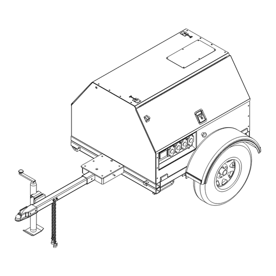
General Information Section 2 General Information Component Locations Figure 2-1. Component Locations Table 2-1. Generator Components Fuel Filler Location (under door) Receptacle Panel (not available on MLG8 units) Radiator Access Panel Ground Studs (2) Control Panel Locations (under door) Safety Chains Emergency Stop Switch (on MLG8 units, Tongue Jack switch is located on front panel) -
Page 10: Unit And Serial Number Locations
General Information Unit and Serial Number Locations Coolant Recommendation Figure 2-2 to locate the unit ID tag (A) and Vehicle DANGER Identification Number (VIN) (B). Important information, such as the unit model number, serial Risk of poisoning. Do not use mouth to number, VIN and tire loading information is found on siphon coolant. -
Page 11: Main Control Panels
TURN MAIN BREAKER OFF GLOW PLUG START NEUTRAL BONDED TO FRAME MLG15 • MLG20 • MLG20ICAN Figure 2-3. Control Panel Component Locations Table 2-2. Control Panel Components Circuit Breaker Indicator Light Engine Hour Meter Main Circuit Breaker 240V Twist-Lock Receptacle... - Page 12 General Information This page intentionally left blank. Owner’s Manual for Mobile Generator...
-
Page 13: Operation
Operation Section 3 Operation Prestart Checklist Starting the Unit Before starting the unit, all items in the prestart checklist DANGER must be completed. Asphyxiation. Running engines produce WARNING carbon monoxide, a colorless, odorless, poisonous gas. Carbon monoxide, if not Consult Manual. Read and understand manual avoided, will result in death or serious injury. -
Page 14: Emergency Stop Switch
Operation Emergency Stop Switch Figure 3-2. As soon as it is glowing, turn the key to START (A) and hold it until the engine cranks and starts running. WARNING In case of an emergency, press the emergency stop button to stop the engine immediately. -
Page 15: Voltage Regulator
Operation Voltage Regulator This unit is equipped with an electronic voltage regulator. The voltage regulator controls the output of the generator by regulating the current into the exciter field. The regulator three screwdriver adjustable potentiometers that may be adjusted for voltage, stability and voltage roll-off (U/F). -
Page 16: Lifting The Unit
Operation Check the wheel lugs. Tighten or replace any lugs Use the forklift pockets with care. Approach the that are loose or missing. If a tire has been unit as perpendicular as possible to avoid removed for axle service or replaced, tighten the damaging the unit. -
Page 17: Emissions Information
Maintenance Section 4 Maintenance Emissions Information bar reaches the red section on the gauge (20 in. For emissions information, see the OEM engine manual. • Check wheel lugs. see Towing the Unit. • Check coolant level daily. See the engine Daily Walk Around Inspection operator’s manual for coolant recommendations and proper mixture. - Page 18 Maintenance Table 4-1. Basic Maintenance Schedule - MLG8 Every 200 Every 400 Every 500 Every 800 Every Two Item Required Hours Hours Hours Hours Years Drain Water Separator Inspect/Adjust Belt Inspect/Clean Fuel Filter Inspect/Replace Air Filter Replace Engine Oil* ...
- Page 19 Maintenance Table 4-3. Basic Maintenance Schedule - MLG20 Every 250 Every 500 Every 1000 Every 12 Item Required Hours Hours Hours Months Drain Water Separator Check Coolant Level Inspect Belt Replace Engine Oil* Replace Engine Oil Filter* ...
-
Page 20: Jack Maintenance
Maintenance Jack Maintenance The following procedures should be performed annually. Side-Wind Models • The internal gearing and bushings of the jack must be kept lubricated. Apply a small amount of automotive grease to the internal gearing by removing the jack cover, or if equipped, use a needle nose applicator or standard grease gun on the lubrication point found on the side of the jack near the crank. -
Page 21: Lower Radiator Hose Heater Option - Use And Maintenance
Maintenance Lower Radiator Hose Heater Option - Use and Maintenance WARNING Personal Injury. Do not modify the location of the lower radiator hose heater. Improper use of hose heater could result in personal injury or engine damage. (000339) The following points should be followed when operating a unit equipped with a lower radiator hose heater. - Page 22 Maintenance This page intentionally left blank. Owner’s Manual for Mobile Generator...
-
Page 23: Wiring Diagrams And Service Log
Wiring Diagrams and Service Log Section 5 Wiring Diagrams and Service Log AC Wiring Diagram W/3-30A, 1-50A Outlets 90212_A_08.27.12 Owner’s Manual for Mobile Generator... -
Page 24: Ac Wiring Panel Options
Wiring Diagrams and Service Log AC Wiring Panel Options TO MAIN BREAKER TO MAIN BREAKER TO NEUTRAL TO GROUND TO NEUTRAL TO GROUND 90319_ORG_07.06.11 90321_ORG_07.06.11 TO MAIN BREAKER TO MAIN BREAKER TO NEUTRAL TO NEUTRAL TO GROUND TO GROUND 90320_ORG_07.06.11 90318_ORG_07.06.11 Owner’s Manual for Mobile Generator... -
Page 25: Ac Wiring Diagram - Mlg 8
Wiring Diagrams and Service Log AC Wiring Diagram - MLG 8 TERMINAL BLOCK 1 MAIN CIRCUIT BREAKER 40 AMP 2 POLE GRN/YEL 20 AMP G.F.I. OUTLET 20 AMP CIRUIT 240 VOLT BREAKER 30 AMP CIRCUIT BREAKER 20 AMP G.F.I. OUTLET 240 VOLT 30 AMP TWIST LOCK... -
Page 26: Dc Wiring Diagram - Mlg 8 And Mlg15
Wiring Diagrams and Service Log DC Wiring Diagram - MLG 8 and MLG15 TERMINAL BLOCK 1 MAIN CIRCUIT BREAKER 40 AMP 2 POLE GRN/YEL 20 AMP G.F.I. OUTLET 20 AMP CIRUIT 240 VOLT BREAKER 30 AMP CIRCUIT BREAKER 20 AMP G.F.I. -
Page 27: Dc Wiring Diagram - Mlg 20
Wiring Diagrams and Service Log DC Wiring Diagram - MLG 20 HOUR 10 AMP CIRCUIT BREAKER 90733_A_07.25.16 Owner’s Manual for Mobile Generator... -
Page 28: Trailer Harness
Wiring Diagrams and Service Log Trailer Harness SPADE SPADE 90341_B_12.20.13 Owner’s Manual for Mobile Generator... -
Page 29: Service Log
Wiring Diagrams and Service Log Service Log OIL GRADE: _____________________________________ BRAND: __________________________________ COOLANT MIXTURE: _____________________________ BRAND: __________________________________ __________________________________________________________________________________________ __________________________________________________________________________________________ __________________________________________________________________________________________ __________________________________________________________________________________________ __________________________________________________________________________________________ __________________________________________________________________________________________ __________________________________________________________________________________________ __________________________________________________________________________________________ __________________________________________________________________________________________ Hours to Coolant Hours to Coolant Date Oil Level Date Oil Level Service Level Service Level Owner’s Manual for Mobile Generator... - Page 30 Wiring Diagrams and Service Log This page intentionally left blank. Owner’s Manual for Mobile Generator...
- Page 32 Part No. 10289 Rev. M 09/09/16 ©2016 Generac Mobile Products LLC. All rights reserved Generac Mobile Products Specifications are subject to change without notice. 215 Power Drive, Berlin, WI 54923 No reproduction allowed in any form without prior written GeneracMobileProducts.com │800-926-9768 │920-361-4442 consent from Generac Mobile Products LLC.
Need help?
Do you have a question about the MLG20ICAN and is the answer not in the manual?
Questions and answers