Advertisement
Quick Links
®
Description
The ISL97656IRTZEVALZ is an evaluation kit for evaluating
the ISL97656, a step-up voltage regulator that operates with
high frequency and high efficiency. This evaluation kit is
designed to deliver up to 2A output current for portable
equipment and TFT-LCD display.
The ISL97656IRTZEVALZ evaluation kit provides a dip
switch that allows users to select either 620kHz or 1.2MHz
frequency.
Key Features
• A Complete Evaluation Platform for the ISL97656
Evaluation
• Input Voltage: 2.3V to 5.5V
• Proven Evaluation Board Layout
• Pb-Free (RoHS Compliant)
What is Needed
The following instruments will be needed to perform testing:
• Power Supplies
• DC Electronic Load
• Multimeters
• Oscilloscope
• Cables and Wires
Pinout
ISL97656
(10L ΜTDFN)
TOP VIEW
COMP
1
FB
2
EN
3
4
GND
GND
5
Ordering Information
PART NUMBER
ISL97656IRTZEVALZ
Evaluation Board for ISL97656
ISL97656IRTZEVALZ Evaluation Board
Application Note
SS
10
9
FREQ
8
IN
7
LX
LX
6
DESCRIPTION
1
CAUTION: These devices are sensitive to electrostatic discharge; follow proper IC Handling Procedures.
1-888-INTERSIL or 1-888-468-3774
Application Manual
May 10, 2010
Quick Setup Guide
1. Connect power supply between headers of V
V
. The positive output of the power supply should
IN_GND
be connected to V
header. Set power supply voltage
IN
between 2.3V and 5V, and current limit at 4A.
2. Connect E-load between headers of V
OUT_GND. The positive input of the E-load should be
connected to V
header. Set E-load current. The load
OUT
current should not exceed the maximum output current in
Table 1.
3. Close pins 1 and 4 of S1 to tie FREQ pin to V
1.25MHz switching frequency. Open pins 1 and 4 to pull
FREQ to ground with R
4
4. Close pins 2 and 3 of S1 to tie EN pin to V
part. Open pins 2 and 3 to pull EN to ground with R
disable the part.
5. Make sure all the connections on the evaluation board
are correct, then turn on power supply and E-load. The
part starts to operate.
Maximum Output Current
The MOSFET current limit is normally 4A and guaranteed
3.8A. This restricts the maximum output current that the
ISL97656 can drive.Table 1 shows typical maximum I
values for 1.2MHz switching frequency and 10µH inductor.
TABLE 1. TYPICAL MAXIMUM I
V
V
IN
OUT
(V)
(V)
2.5
5
2.5
9
2.5
12
3.3
5
3.3
9
3.3
12
5
9
5
12
|
Intersil (and design) is a registered trademark of Intersil Americas Inc.
Copyright Intersil Americas Inc. 2009, 2010. All Rights Reserved
All other trademarks mentioned are the property of their respective owners.
AN1473.1
and
IN
and
OUT
to set
IN
to set 620kHz.
to enable the
IN
to
3
OUT
VALUES
OUT
I
OMAX
(mA)
1790
990
750
2370
1300
970
1970
1470
Advertisement

Related Manuals for Intersil ISL97656IRTZEVALZ


Summary of Contents for Intersil ISL97656IRTZEVALZ
-
Page 1: Application Note
CAUTION: These devices are sensitive to electrostatic discharge; follow proper IC Handling Procedures. 1-888-INTERSIL or 1-888-468-3774 Intersil (and design) is a registered trademark of Intersil Americas Inc. Copyright Intersil Americas Inc. 2009, 2010. All Rights Reserved All other trademarks mentioned are the property of their respective owners. - Page 2 FY0504SA 22µF GNDIN CON1 NOTE: The thermal pad should connect to signal ground. Both grounds should connect at pins 4 and 5. FIGURE 1. SCHEMATIC TABLE 2. ISL97656IRTZEVALZ BILL OF MATERIALS (BOM) ITEM REFERENCE PART DESCRIPTION PCB FOOTPRINT PART NUMBER...
-
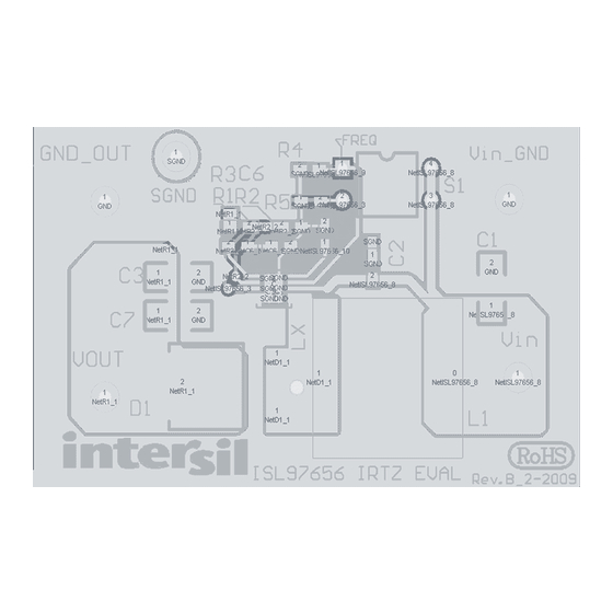
Page 3: Pcb Layout
Application Note 1473 PCB Layout FIGURE 1. EVALUATION BOARD ASSEMBLY LAYER FIGURE 2. TOP LAYER AN1473.1 May 10, 2010... - Page 4 FIGURE 3. BOTTOM LAYER Intersil Corporation reserves the right to make changes in circuit design, software and/or specifications at any time without notice. Accordingly, the reader is cautioned to verify that the Application Note or Technical Brief is current before proceeding.
Need help?
Do you have a question about the ISL97656IRTZEVALZ and is the answer not in the manual?
Questions and answers