Table of Contents
Advertisement
Quick Links
ISL97676IRZ-EVAL Quick Start Guide
This quick start guide pertains to the ISL97676IRZ-EVAL.
This board comes populated with 72 LED's in a 6P12S
configuration to simplify evaluation and testing.
1. Apply input voltage to the VIN and GND post on the
top left corner of the evaluation board.
2. Apply a 100% duty-cycle PWM signal to PWM (J13)
and GND post.
3. Insert WR jumper.
4. To power-up the evaluation board in 6P12S
configuration, make sure jumpers JP8-14 are
inserted.
5. To power-up in 6P10S configuration, jumpers JP15-20
should be inserted.
6. Jumper JP5 should be inserted in the lower position.
See Figure 1.
7. Jumper J12 should be inserted in the top position.
See Figure 1.
8. LED current can be programmed by connecting a
current meter across J8 and varying R12.
ILED = 724/R12
The measured current divided by 6 is the LED current per
channel. For example, 120mA measured current will
correspond to 20mA/channel.
9. Floating jumper JP7 will provide direct PWM mode
such that the dimming frequency follows the input
PWM signal without frequency modulation. See
ISL97676 data sheet for more details (FN7600).
Note that equal phase shift feature is disabled in this
mode.
10. Inserting JP7 allows the dimming frequency to be
programmed with a resistor, R12 to GND. The
dimming frequency is calculated by Equation 1:
×
⁄
FPWM
6.67
10^7
RFPWM
=
July 15, 2010
AN1568.0
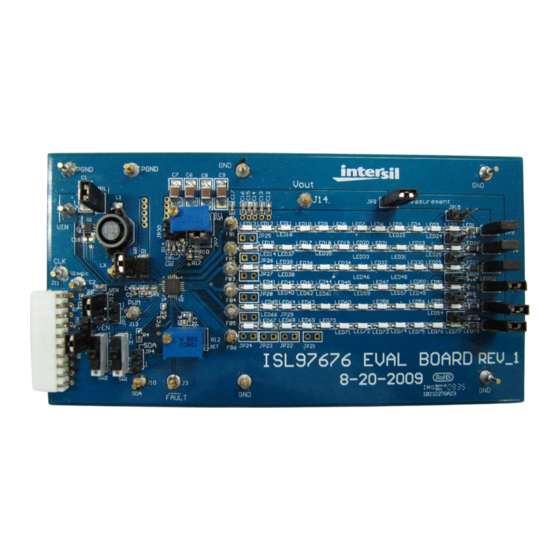
FIGURE 1. ISL97676 EVALUATION BOARD
(EQ. 1)
1
CAUTION: These devices are sensitive to electrostatic discharge; follow proper IC Handling Procedures.
1-888-INTERSIL or 1-888-468-3774
Application Note 1568
11.Switches SW1 and SW2 are used to program the
switching frequency and enable the equal phase
shift feature per Table 1. For additional information,
please consult the ISL97676 data sheet.
SW2
SW1
Up
Up
F
= 1.2MHz, Equal Phase Shift Enabled
SW
Up
Down F
= 570kHz, No Phase Shift
SW
Down
Up
F
= 1.2MHz, No Phase Shift
SW
Down Down F
= 570kHz, Equal Phase Shift Enabled
SW
12.After following Steps 1 through 9, all 72 LEDs should
light up at 100% duty-cycle or full brightness.
13.Jumper JP1 can be inserted if the external fault
MOSFET Q1 is not used. See data sheet for
additional information.
14.Jumpers JP4, JP3, JP30 and the 10-pin white
connector in the bottom left are not used.
The ISL97676 evaluation board schematic and top and
bottom silkscreen layers are shown in Figures 2 through 4.
|
Intersil (and design) is a registered trademark of Intersil Americas Inc.
Copyright Intersil Americas Inc. 2010. All Rights Reserved
All other trademarks mentioned are the property of their respective owners.
TABLE 1.
Advertisement
Table of Contents

Related Manuals for Intersil ISL97676IRZ


Summary of Contents for Intersil ISL97676IRZ
-
Page 1: Application Note
CAUTION: These devices are sensitive to electrostatic discharge; follow proper IC Handling Procedures. AN1568.0 1-888-INTERSIL or 1-888-468-3774 Intersil (and design) is a registered trademark of Intersil Americas Inc. Copyright Intersil Americas Inc. 2010. All Rights Reserved All other trademarks mentioned are the property of their respective owners. - Page 2 Sheet Sheet Intersil Corporation reserves the right to make changes in circuit design, software and/or specifications at any time without notice. Accordingly, the reader is cautioned to verify that the Application Note or Technical Brief is current before proceeding. For information regarding Intersil Corporation and its products, see www.intersil.com July 15, 2010 AN1568.0...
- Page 3 FIGURE 3. EVALUATION BOARD TOP LAYER...
- Page 4 FIGURE 4. EVALUATION BOARD BOTTOM LAYER...
Need help?
Do you have a question about the ISL97676IRZ and is the answer not in the manual?
Questions and answers