Table of Contents
Advertisement
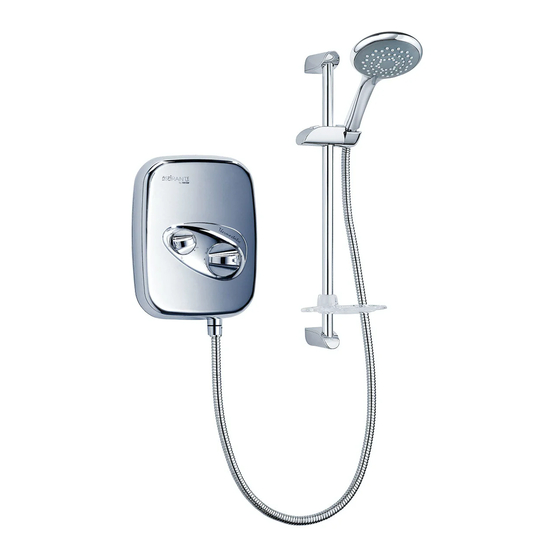
Aspirante
power shower
Installation and
operating
instructions
I
nstallers please note these
InstructIons are to be left wIth
the user
The showerhead and hose supplied with this product are an integral
part of the safety of your shower. Failure to use genuine Triton
parts may cause injury and will invalidate your warranty
2180298Q - December 2015
Advertisement
Table of Contents

Related Manuals for Triton ASPIRANTE THERMOSTATIC POWER SHOWER


Summary of Contents for Triton ASPIRANTE THERMOSTATIC POWER SHOWER
- Page 1 InstructIons are to be left wIth the user The showerhead and hose supplied with this product are an integral part of the safety of your shower. Failure to use genuine Triton parts may cause injury and will invalidate your warranty 2180298Q - December 2015...
-
Page 2: Table Of Contents
Children may not play with the appliance. Cleaning and user maintenance shall not be made by children without supervision. To check the product suitability for commercial and multiple installations, please contact Triton’s speci cation advisory service before installation. Telephone:... -
Page 3: Plumbing And Electrical Notes
Aspirante thermostatic power shower PLUMBING NOTES ELECTRICAL NOTES 1.1 All installations must comply with Water 2.1 The installation must comply with BS 7671 Regulations or Water Bylaws. ‘Requirements for electrical installations’ (IEE wiring regulations). Make sure the 1.2 Supply pipes must be flushed to clear incoming hot and cold water supplies to debris before connecting the shower unit. -
Page 4: Introduction
A 30mA residual current device (RCD) MUST be installed in all UK 230V electric and pumped shower circuits. This may be part of Replacement parts can be ordered from Triton the consumer unit or a separate unit. Customer Service. See ‘spare parts’ for details and part... -
Page 5: Main Components
Aspirante thermostatic power shower MAIN COMPONENTS Fig.1 1. Top pipe entry and cable entry 2. Terminal block 3. Cover screw fixing 4. Motor retaining bracket 5. Rear pipe entry and cable entry 6. Wall fixing holes 7. Pipe inlet elbow – top (contains single check valves) 8. -
Page 6: Site Requirements - Water
Aspirante thermostatic power shower SITE REQUIREMENTS Fig.3 illustrates all the incorrect connections that must be avoided. Water All pipework to the shower unit must be routed The installation must be in accordance with where it remains below the level of water in Water Regulations. -
Page 7: General Installation Notes
Aspirante thermostatic power shower the infill rate from the float operated valve meets 5. The unit must be mounted onto the finished the output requirements. wall surface (on top of tiles). DO NOT tile up to the unit after fixing to the wall. -
Page 8: Siting Of The Shower
Aspirante thermostatic power shower SITING OF THE SHOWER Fig.4 (schematic view ) WARNING! Potentiometer The shower must not be positioned where it will be subjected to freezing conditions. Switch Thermal fuse FOR EASE OF SERVICING, THE APPLIANCE MUST ALWAYS BE MOUNTED ON THE SURFACE Motor OF TILED WALLS. -
Page 9: Removing The Cover
Aspirante thermostatic power shower REMOVING THE COVER Fig.6 Note: When you first receive your Aspirante power shower, the temperature control knob and cover fixing screws will be packaged separately within the box. In this instance just carefully remove the cover and proceed to ‘Plumbing connections’... -
Page 10: Plumbing Connections
Aspirante thermostatic power shower PLUMBING CONNECTIONS Fig.9 Cold Rear edge Plumbing to be completed before wiring backplate Note: The outlet of the shower must not be connected to any tap or fitting not recommended by Triton Plc. 98 mm DO NOT use jointing compounds on any pipe fittings for the installation. - Page 11 Aspirante thermostatic power shower inlet must be cut out, including the top left IMPORTANT: The inlets contain check wall fixing hole. valves, so before completing the connection When fitting the elbows to incoming of the water supplies to the shower flush...
-
Page 12: Fitting The Shower To The Wall
Aspirante thermostatic power shower FITTING THE SHOWER TO THE WALL Fig.14 IMPORTANT: Prior to fitting the shower, make sure that the plumbing is flushed out, removing all debris, flux, etc. For top pipe entry or top cable entry, remove the relevant cut-outs by either breaking out or by using a knife or junior hack saw (fig.14). - Page 13 Aspirante thermostatic power shower Note: If fitting rising supplies to the unit, make Fig.17 sure that debris does not enter the pipes when drilling the wall. Offer the back plate unit up to the completed pipework and manoeuvre so that the end of the pipes enter fully into the inlet fittings.
-
Page 14: Electrical Connections
Aspirante thermostatic power shower ELECTRICAL CONNECTIONS Terminal block Fig.18 WARNING! THIS APPLIANCE MUST BE EARTHED The supply cable must conform to relevant tables in current IEE regulations. In most cases 1 mm² twin and earth will be adequate. The electrical rating of the shower is on the rating label within the unit. -
Page 15: Commissioning And Setup Procedure
Aspirante thermostatic power shower COMMISSIONING Fig.19 WARNING! Before normal operation of the shower, it is essential that the commissioning and setup procedure are correctly completed. Failure to do so could cause the pump to run dry without water and invalidate your guarantee. - Page 16 Aspirante thermostatic power shower Note: The temperature control rotates less than one complete turn (fig.21) – from 3 o’ clock Fig.22 (cold) anti-clockwise to 6 o’ clock position (hot) and visa versa. DO NOT force it beyond these limits. To stop the water flow, switch off the electricity supply at the isolating switch.
-
Page 17: Replacing The Cover
Aspirante thermostatic power shower REPLACING THE COVER Fig.24 IMPORTANT:Make sure that the earth contact spring within the unit is not distorted before replacing the cover. Fit the cover, making sure the connector is fitted to the PCB and the wires are clear of the setting adaptor. -
Page 18: Temperature Control Spindle Setting
Aspirante thermostatic power shower TEMPERATURE CONTROL SPINDLE Fig.26 SETTING Occasionally the spindle may need adjusting when the temperature control and cover are Groove removed from the unit. To reset the spindle to its correct alignment, please refer to the Drilled hole... -
Page 19: Operating The Shower
Aspirante thermostatic power shower OPERATING THE SHOWER Fig.28 Make sure all plumbing and electrical supplies are connected and switched on. To start the shower, rotate the flow control clockwise from the ‘stop’ position (fig.28). Adjust the control until the flow rate is satisfactory. -
Page 20: Adjusting The Maximum Temperature Stop
Aspirante thermostatic power shower ADJUSTING THE MAXIMUM Fig.32 TEMPERATURE STOP As a safety feature the shower has a built-in maximum temperature stop to prevent you accidentally exceeding your highest desired temperature. This is set in the factory to provide a maximum temperature based on the hot and cold water supplies being 65°C and 15°C... -
Page 21: Cleaning
DO NOT use abrasive or aggressive switched on. cleaning products when cleaning the Triton recommends that all products are cleaned shower as they may damage the unit. using warm, soapy water. DO NOT use abrasive or aggressive chemical cleaning products as this may affect the product surface finish and invalidate your guarantee. -
Page 22: Instructions For Installers And Service Engineers Only
Aspirante thermostatic power shower INSTRUCTIONS FOR INSTALLERS AND SERVICE ENGINEERS ONLY INSTRUCTIONS FOR INSTALLERS AND SERVICE ENGINEERS CLEANING THE FILTERS Fig.34 Upper filter shown Note: Isolate the electricity and both hot and cold water supplies to the unit before proceeding further. -
Page 23: Spare Parts
Aspirante thermostatic power shower SPARE PARTS Ref. Description Part No. 1. Terminal block ......22001320 2. Plastic inlet elbow plug x1 ..7052140 3. Pump & motor assembly..84000130 4. Commissioning link ....22009060 5. PCB unit ........7073738 6. Temperature valve ....83305270 (thermostatic) 7. -
Page 24: Fault Finding
Aspirante thermostatic power shower FAULT FINDING Symptom Cause Action/Cure 1 Water too hot. 1.1 Not enough cold 1.1.1 Turn the temperature control clockwise. water flowing through shower. 1.2 Increase in the 1.2.1 Turn the temperature control clockwise. ambient cold water temperature. - Page 25 It is advised all electrical maintenance/repairs to the shower should be carried out by a suitably qualified person. In the unlikely event of a fault occurring please contact Triton Customer Service. Do not remove the shower from the installation.
-
Page 26: Water/Cable Entry Points Diagram
Aspirante thermostatic power shower Entry Points Diagram Key: Water Entry Points Right: bottom, back, top. Cable Entry Points Right: back, top. - Page 27 Aspirante thermostatic power shower WEEE Directive – Policy Statement As a producer and a supplier of electric showers, Triton Showers is committed to the protection of the environment via our own environmental policy and the compliance with the WEEE directive.
- Page 28 fixed charge. substances. 9. If a debt is outstanding from a previous visit, or from any other Triton 4. Total loss of the product due to non-availability of parts. purchase, Triton reserves the right to withhold service until the debt 5.
Need help?
Do you have a question about the ASPIRANTE THERMOSTATIC POWER SHOWER and is the answer not in the manual?
Questions and answers