
Related Manuals for Carrier 50UA-UH 135


Summary of Contents for Carrier 50UA-UH 135
- Page 1 INSTALLATION, OPERATION AND M A I N T E N A N C E I N S T R U C T I O N S Packaged Rooftop Cooling Only Units and Heat Pumps Original document...
-
Page 2: Table Of Contents
7- APPLICATION DATA ................................24 7.1 – Belt tension ..................................... 24 ................................24 7.3 - Fan performances, 48/50UA-UH 135-160 ..........................25 7.4 - Fan performances, 48/50UA-UH 180 ........................... 26 7.5 - Fan performances, 48/50UA-UH 205 ...........................27 7.6 - Pressure drop, options (Pa) .............................. -
Page 3: Introduction
11 - OPERATING LIMITS ................................34 12 -GAS HEATING (48UA/UH ONLY) ..........................35 12.1 - Introduction ..................................35 12.2 Preliminary checks before start-up ............................35 12.3 Safety instructions ................................35 12.4 Installation of the gas heating module ........................... 36 12.5 Commissioning ..................................37 12.6 Combustion Analysis ................................39 12.7 Operating sequence ................................40... - Page 4 Transport and lifting and maintenance easier and more secure. They will provide safe and reliable service when operated within should be lifted with lifting bars supplied by Carrier. Lifting their application range. must be carried out in accordance with local regulations and...
-
Page 5: Equipment And Components Under Pressure
• IMPORTANT INFORMATION REGARDING These products incorporate equipment or components under THE REFRIGERANT USED: pressure, manufactured by Carrier or other manufacturers. covered by the Kyoto protocol. We recommend that you consult your appropriate national Refrigerant type: R-410A trade association or the owner of the equipment or compo-... -
Page 6: Repair Safety Considerations
"CAUTION: If the test leads to replacing the pressure refrigerant circuit component until all refrigerant (liquid and switch, it is necessary to recover the refrigerant charge, vapour) and the oil have been removed from the unit. Traces these pressure switches are not installed on automatic of vapour should be displaced with dry nitrogen. -
Page 7: Moving And Siting The Unit
Fig. 1 – Fastening the lifting bars - 1 refrigerant and hydronic circuits to ensure that they do not show any corrosion or any signs of leaks. It is recommended to wear ear defenders, when working near the unit and the unit is in operation. Always ensure you are using the correct refrigerant type before recharging the unit. -
Page 8: Siting The Unit
• Position the lifting cables on the lifting bars 2.3 - Checks before system start-up Evenly positioned spacer bars should be used between the lifting cables to prevent damage to Before the start-up of the refrigeration system, the complete the top of the unit and ensure that no excess pressure is applied to the side panels. -
Page 9: Installation
3 - INSTALLATION Fig. 4 – Roofcurb accessory - standard vertical discharge and return 3.1 - Unit base frame This unit is for connection to a ducted air system only. It should not be used without ductwork connected to the air outlet or discharge side of the unit. -
Page 10: Ductwork
IMPORTANT: The unit should be correctly levelled to avoid drainage problems. Determine the ductwork dimensions according to the air The room temperature sensor and supply temperature sensor supply, are shown in the fan performance tables. are located in the control box together with their connectors. Please refer to the wiring diagrams for the required connec- It is recommended to observe the following considerations: tions and suitable cable diameter. - Page 12 The units incorporate drillholes in the base near the outdoor coils to drain rainwater and condensation. The indoor heat exchanger area incorporates a condensate pan with an outside drain pipe diameter of 34mm and a negative drainage siphon as in Fig. 8. Min. recommended value of X is 180 mm.
- Page 13 50UA-UH 135 Control box Power cable entry Control cable entry Service clearances required Supply air Return air Air outlet, do not obstruct When designing an installation, always use up-to-date the units with options such as economizer, power exhaust, air return fan, etc.
- Page 14 50UA-UH 160 Control box Power cable entry Control cable entry Service clearances required Supply air Return air Air outlet, do not obstruct When designing an installation, always use up-to-date the units with options such as economizer, power exhaust, air return fan, etc.
- Page 15 50UA-UH 180 Control box Power cable entry Control cable entry Service clearances required Supply air Return air Air outlet, do not obstruct When designing an installation, always use up-to-date the units with options such as economizer, power exhaust, air return fan, etc.
-
Page 16: Fan Performances, 48/50Ua-Uh 205
50UA-UH 205 Control box Power cable entry Control cable entry Service clearances required Supply air Return air Air outlet, do not obstruct When designing an installation, always use up-to-date the units with options such as economizer, power exhaust, air return fan, etc. -
Page 17: Electrical Connections
Fames Exhaust Ø80 Air intake Ø80 Air outlet, do not obstruct When designing an installation, always use up-to-date drawings, available from your local Carrier Please refer to the dimensional drawings for the units with options such as economizer, power exhaust, air return fan, etc. - Page 18 Fames Exhaust Ø80 Air intake Ø80 Air outlet, do not obstruct When designing an installation, always use up-to-date drawings, available from your local Carrier Please refer to the dimensional drawings for the units with options such as economizer, power exhaust, air return fan, etc.
- Page 19 Fames Exhaust Ø80 Air intake Ø80 Air outlet, do not obstruct When designing an installation, always use up-to-date drawings, available from your local Carrier Please refer to the dimensional drawings for the units with options such as economizer, power exhaust, air return fan, etc.
- Page 20 Fames Exhaust Ø80 Air intake Ø80 Air outlet, do not obstruct When designing an installation, always use up-to-date drawings, available from your local Carrier Please refer to the dimensional drawings for the units with options such as economizer, power exhaust, air return fan, etc.
- Page 21 Multiple rooftop installation 2175 2250 2870 3260 Sound power level 10-12 W** dB(A) 93.5 93.8 Sound pressure level at 10 m*** dB(A) Hermetic Scroll Circuit A Circuit B No. of capacity steps POE 160SZ Circuit A 13.4 Circuit B 13.4 R410A Circuit A 25.5...
- Page 22 2190 2265 2890 3280 Sound levels Sound power level 10-12 W** dB(A) 93.5 93.8 Sound pressure level at 10 m*** dB(A) Hermetic Scroll Circuit A Circuit B No. of capacity steps POE 160SZ Circuit A 13.4 Circuit B 13.4 R410A Circuit A 21.5 Circuit B...
- Page 23 4. Overcurrent protection of the power supply conductors is not provided with the accordance with all applicable local codes. unit. - The Carrier UA-UH 135-205 units are designed and built to ensure 5. The factory-installed disconnect switch(es)/circuit breaker(s) is(are) of a type confor-mance with these codes.
-
Page 24: Belt Tension
On delivery, the drive belts are new and correctly tensioned. After the belts have run-in, stop the belt drive and check the belt tension. Running the belts under full load for an extended period of time will seat the V-belts into the sheave grooves. - Page 25 1165 23,740 1181 24,296 1196 24,856 Out of fan scope 7.3.1 - Fan RPM at Motor Pulley Settings - Unit 50UA-UH 135-160* FAN RPM AT MOTOR PULLEY SETTINGS - Unit 48/50UH-UA MOTOR PULLEY TURNS OPEN Drive 1-1/2 2-1/2 3-1/2 4-1/2...
- Page 26 3.822 4.237 4.668 5.113 5.569 6.036 6.510 6.992 7.485 7.985 4.325 4.759 5.205 5.664 6.139 6.621 7.113 7.614 8.125 8.644 4.844 5.289 5.753 6.227 6.716 7.213 7.724 8.243 8.769 9.302 5.399 5.863 6.341 6.830 7.334 7.845 8.371 8.905 9.449 10.001 6.050 6.529 7.022...
- Page 27 3.546 3.950 4.373 4.807 5.256 5.712 6.183 6.661 7.147 7.643 4.002 4.425 4.859 5.311 5.771 6.245 6.731 7.227 7.731 8.243 4.473 4.907 5.355 5.819 6.297 6.786 7.286 7.798 8.316 8.842 4.980 5.425 5.889 6.367 6.860 7.364 7.875 8.401 8.934 9.478 5.576 6.039 6.518...
- Page 28 Pressure Drops, Options (Pa) 48/50 UA/UH 135 and 160 5.400 5.800 6.200 6.600 7.000 7.400 7.800 8.200 8.600 9.000 Unit Air flow rate 19.440 20.880 22.320 23.760 25.200 26.640 28.080 29.520 30.960 32.400 Opt 174 - Electric heater Opt 175 - Electric heater Opt 176 - Electric heater Opt 180 - Hot water coil Opt 181 - Hot water coil...
- Page 29 48/50 UA/UH 205 7.200 7.650 8.100 8.550 9.000 9.450 9.900 10.350 10.800 11.250 Unit Air flow rate 25.920 27.540 29.160 30.780 32.400 34.020 35.640 37.260 38.880 40.500 Opt 177 - Electric heater Opt 178 - Electric heater Opt 179 - Electric heater Opt 182 - Hot water coil Opt 183 - Hot water coil Opt 211- Natural gas...
- Page 30 5456 8184 5736 8604 7264 10896 7336 11004 The drive is factory set in accordance with the standard fan performance tables. nominal ratings, the motor pulley can be adjusted for diffe- rent available static pressure values (see fan performance tables). To change the fan speed: Move the motor along its track in order to remove the belt.
- Page 31 The following is only to be used as a guide- injury may occur. line, and does not make Carrier in any way liable. After wire Field wiring must comply with all applicable codes. Take drawing, the installer must ensure easy connection and special care when making the earth connection with the main earth bar inside the control box.
- Page 32 (length L in metres - see table below). and maintenance purposes. 1 x6 PVCCu 1 x10 PVCCu the unit nameplate rating. 1 x16 PVCCu 1 x25 PVCCu isolators. 1 x35 PVCCu 1 x50 PVCCu 1 x70 PVCCu WARNING: The compressors are mounted on vibration 1 x95 PVCCu isolators.
- Page 33 NOTE: Use only oils which have been approved for the compressors. Never use oils which have been exposed to air. UA-UH135-205 units use hermetic scroll compressors. R-410A oils and vice versa. Each compressor is equipped with a crankcase oil heater, as standard for all units.
- Page 34 ecodesign requirements for electric motors. Motor type Dual-speed asynchronous Number of poles Nominal input frequency Nominal voltage Number of phases Motor included in the application domain of the regulation 640/2009 and amendment 4/2014 Article 2.1 °C 68.5 UA-UH135-205 units are equipped with automatically reset high-pressure safety switches, calibrated to 4420 kPa relative pressure (unit alarm is manually reset).
- Page 39 PCH 080 Gas intake pressure PCH 105 Connector (IN) OFFSETpressure Connector (Pascal) OFFSET adjustment screw adjustment adjustment Venturi...
- Page 40 Gas valve EV1 and EV2 Ignition electrode Detection electrode Pilot burner...
- Page 43 FAULT DESCRIPTION CAUSE REMEDY Lockouts caused by Flame - Related to the TER equipment Failure to ignite flame after 4 attempts • Phase and neutral reversed. performed by the equipment. • Earth wire not connected. • Phase-phase connection without neutral. Ill-timed flame (Flame detection before •...
- Page 44 the table below: 1 .1 Shielded electric resistance heaters are fully factory-wired 5456 8184 and tested. Each stage is protected against overloads by two 5736 8604 thermal protectors. The low-limit protector with 7264 10896 automatic reset is located above the resistance heaters while 7336 11004 the high-limit protector with manual reset is located in the...
- Page 45 When the outdoor conditions are maintained based on Damper with direct link driven blades, can be preset to admit up to 40% outside air into the return-air compart- free cooling can be provided using fresh air. The economizer ment. To adjust, loosen the securing screw and rotate the arm of the damper blades to the desired setting.
- Page 46 The power exhaust performance curves are shown below: The indoor air quality is controlled by the Touch Pilot 8000 3.00 control via the input from the CO sensor, adjusting the 7000 economizer. Please refer to the Touch Pilot IOM for the 2.50 6000 control logic.
- Page 47 smoke detector is located in the return air side. If smoke is reduction in supply fan power consumption when needed. detected, there will be an alarm on the Touch Pilot control and the necessary actions will be taken. This smoke detection pulleys with variable frequency drive (VFD).
- Page 48 13.13.1 - Fan performances 48/50UA-UH with Variable Air Volume supply fan...
- Page 49 1 .13.1 - Fan performances 50UA-UH with Variable Air Volume supply fan (continued) 48/50 UA/UH 205 VAV option Unit External Static Pressure (Pa) 1040 1120 1200 3,600 4,011 4,881 5,799 7,114 8,861 10,691 12,592 1031 14,556 1111 17,110 1151 18,499 1190 19,911 7.000...
- Page 50 Return air fan performances...
- Page 51 Return air fan performances Return Fan - Opt 205 - VAV - 135-160 Unit External Sta c Pressure (Pa) 5200 3,173 3,495 3,829 4,170 4,521 4,879 5,244 5500 3,630 3,966 4,312 4,667 5,033 5,405 5,784 5800 4,134 4,485 4,845 5,215 5,592 5,977 6,371...
- Page 52 Vertical discharge roof curb All maintenance operations must be carried out by techni- cians who have been trained on Carrier products, observing all Carrier quality and safety standards. Air outlet During the unit operating life the service checks and tests...
- Page 53 1’, the thermostatic expansion valve. The bulb is best (see report in the Touch Pilot control manual), necessary. Carrier ERCD reference: 7754024. Replace them if there is a fault. heat exchanger inlet and outlet is correct. Replace it if necessary.
- Page 54 NOTE: Any deviation or non-observation of these mainte- nance criteria will render the guarantee conditions for the HVAC unit nul and void, and the manufacturer, Carrier, will no longer be held responsible. check the degree of fouling. This depends on the environment where the unit is installed, and will be worse in urban and industrial installations and near trees that shed their leaves.
- Page 55 Correct and frequent cleaning (approximately every three Protect the control box during cleaning operations. circuit, ensure that the entire refrigerant charge is removed from both the high and low pressure sides of the unit. sensitive. If they need to be replaced, care should be the unit charge is correct, by checking the actual subcooling.
-
Page 56: Power Supply
A list of possible faults, as well as the probable cause and suggested solutions is shown in the table below. In the event of a unit malfunction it is recommended to disconnect the power supply and ascertain the cause. No power supply Connect power supply Main switch open Close main unit disconnect switch... -
Page 57: Power Supply
Preliminary information Job name: ....................................... Location: ........................................ Installing contractor:..................................... Distributor: ......................................Start-up preformed by: .............. Date: ....................Equipment Model UA-UH135-205 : ..............................Compressors Circuit A Circuit B 1. Model No.................. 1. Model No................Serial No................... Serial No................2. - Page 58 Carry out the QUICK TEST function (see UA-UH135-205 Touch Pilot control manual): Re-enter the setpoints (see controls section) To start up the unit Once all checks have been made, start the unit in the “LOCAL ON” position. Unit starts and operates properly Temperatures and pressures WARNING: have stabilized, record the following:...
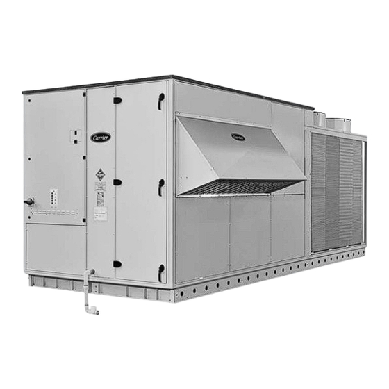
- Page 59 02.2017. 10117, 10.2015 Order No.: 10117, 10.2015. Supersedes order No.: Manufacturer: Alarko-Carrier, Gebze, Turkey. The front cover photos are for illustration purposes only and not contractually binding.
Need help?
Do you have a question about the 50UA-UH 135 and is the answer not in the manual?
Questions and answers