Carrier Comfort 50ES-A Installation Instructions Manual
Comfortt 13 seer single-packaged air conditioner system with puron (r-410a) refrigerant single and three phase 2-5 nominal tons (sizes 24-60)
Hide thumbs
Also See for Comfort 50ES-A:
- Owner's information manual (6 pages) ,
- Owner's information manual (6 pages) ,
- Owner's information manual (6 pages)
Table of Contents
Advertisement
50ES---A
Comfortt 13 SEER Single ---Packaged Air Conditioner System
With Puron® (R ---410A) Refrigerant
Single and Three Phase
2---5 Nominal Tons (Sizes 24---60)
NOTE:
Read the entire instruction manual before starting the
installation.
NOTE:
Installer: Make sure the Owner's Manual and Service
Instructions are left with the unit after installation.
TABLE OF CONTENTS
. . . . . . . . . . . . . . . . . . . . . . . . . . . . . . . . . . .
. . . . . . . . . . . . . . . . . . . . . . . . . . . . . . . . . .
. . . . . . . . . . . . . . . . . . . . . . . . . . . . . . . . . . . .
. . . . . . . . . . . . . . . . . . . . . . . . . . . . . . . . .
. . . . . . . . . . . . . . . . . . . . . . . . . . . . . . .
. . . . . . . . . . . . . . . . . . . . . . . . . . . . . . . . . . . . . .
. . . . . . . . . . . . . . . . . . . . . . . . . . . . . . . . . . . . .
. . . . . . . . . . . . . . . . . . . . . . . . . . . . . . . . .
. . . . . . . . . . . . . . . . . . . . . . . . . . . .
. . . . . . . . . . . . . . . . . . . . . . . . . . . . . . . . .
. . . . . . . . . . . . . . . . . . . . . . . . . . . . . . . . . . . . . .
. . . . . . . . . . . . . . . . . . . . . . . . . . . .
. . . . . . . . . . . . . . . . . . . . . . . . . . . . .
. . . . . . . . . . . . . . . . . . . . . . . . . . . . . .
. . . . . . . . . . . . . . . . . . . . . . . . . . . .
. . . . . . . . . . . . . . . . . . . . . . . . . . . . . . . . . . .
. . . . . . . . . . . . . . . . . . . . . . . . . . . . . . . . . . . . .
. . . . . . . . . . . . . . . . . . . . . . . . . . . . . .
. . . . . . . . . . . . . . . . . . . . . . . . . . . . . . . .
. . . . . . . . . . . . . . . . . . . . . . . . . . . . . . . . . . . . . .
. . . . . . . . . . . . . . . . . . . . . . . . . . . . . . . . . . .
. . . . . . . . . . . . . . . . . . . . . . . . . . . . . . .
. . . . . . . . . . . . . . . . . . . . . . . . . . . . . .
. . . . . . . . . . . . . . . . . . . . . . . . . . . . . . . . . . . .
. . . . . . . . . . . . . . . . . . . . . . . . . . . . . .
. . . . . . . . . . . . . . . . . . . . . . . . . . . .
Installation Instructions
. . . . . . . . . . . . . . . . . . . . . . . . .
. . . . . . . . . . . . . . . . . .
. . . . . . . . . . . . . . . . . . . . . . . . . . .
. . . .
. . . . . . . . . . . . . . . . . . . . . . . . .
. . . . . . . . . . . . . . . . . . . . . . . . .
. . . . . . . . . . . . . . . .
. . . . . . . . . . . . . . . . . . . . . . . .
. . . . . . . . . . . . . . . . . . . . . . . . .
. . . . . . . . . . . . . . . .
. . . . . . . . . . .
. . . . . . . . . . . . .
. . . . . . . . . . . . . . . . . . .
. . . . . . . . . . . . . . . . . . . .
. . . . . . . . . . . . . . . . . . . . . . . .
. . . . . . . . . . . . . . . . . . . . .
. . . . . . . . . . . . . . . . . . . . . . . . .
. . .
. . . . . . . . . . . . . . . . . . . . .
PAGE
1
2
2- -9
2
2
2
2
2
SAFETY CONSIDERATIONS
2
2
Installation and servicing of this equipment can be hazardous due
2
to mechanical and electrical components. Only trained and
2
qualified personnel should install, repair, or service this equipment.
2
Untrained personnel can perform basic maintenance functions such
6
as cleaning and replacing air filters. All other operations must be
7
performed by trained service personnel. When working on this
7
equipment, observe precautions in the literature, on tags, and on
7
labels attached to or shipped with the unit and other safety
8
precautions that may apply.
9
Follow all safety codes. Installation must be in compliance with
9
local and national building codes. Wear safety glasses, protective
9
clothing, and work gloves. Have fire extinguisher available. Read
9
these instructions thoroughly and follow all warnings or cautions
9
included in literature and attached to the unit.
11
11- -13
Recognize safety information. This is the safety- -alert symbol
11
When you see this symbol on the unit and in instructions or manu-
11
als, be alert to the potential for personal injury. Understand these
11
signal words: DANGER, WARNING, and CAUTION. These
11
words are used with the safety- -alert symbol. DANGER identifies
12
the most serious hazards which will result in severe personal injury
12
or death. WARNING signifies hazards which could result in per-
12
sonal injury or death. CAUTION is used to identify unsafe practic-
13
es which may result in minor personal injury or product and prop-
13
erty damage. NOTE is used to highlight suggestions which will
19- -21
result in enhanced installation, reliability, or operation.
19
19
!
20
20
ELECTRICAL SHOCK HAZARD
20
21
Failure to follow this warning could result in personal
21
injury or death.
21
Before installing or servicing system, always turn off main
22
power to system and install lockout tag. There may be
22
more than one disconnect switch. Turn off accessory heater
power switch if applicable.
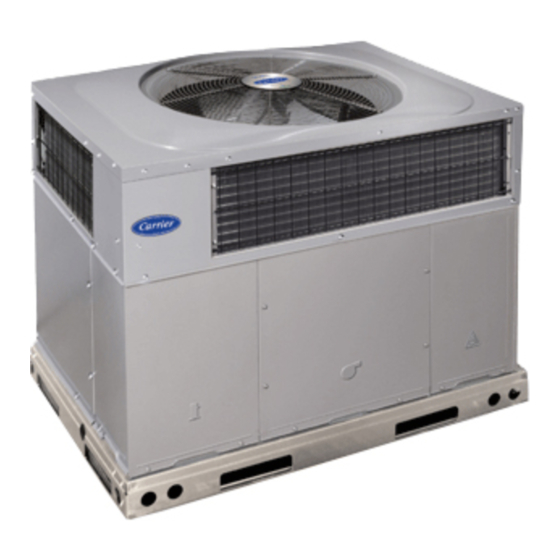
1
Fig. 1 - - Unit 50ES- -A
WARNING
A09034
.
Advertisement
Table of Contents

Related Manuals for Carrier Comfort 50ES-A


Summary of Contents for Carrier Comfort 50ES-A
-
Page 1: Table Of Contents
50ES---A Comfortt 13 SEER Single ---Packaged Air Conditioner System With Puron® (R ---410A) Refrigerant Single and Three Phase 2---5 Nominal Tons (Sizes 24---60) Installation Instructions NOTE: Read the entire instruction manual before starting the installation. NOTE: Installer: Make sure the Owner’s Manual and Service Instructions are left with the unit after installation. -
Page 2: Introduction
SLAB MOUNT WARNING Place the unit on a solid, level concrete pad that is a minimum of 4 in. (102 mm) thick with 2 in. (51 mm) above grade. The slab PERSONAL INJURY ENVIRONMENTAL should extend approximately 2 in. (51 mm) beyond the casing on HAZARD all 4 sides of the unit (See Fig. - Page 3 A09113 Fig. 2 - - 50ES- -A24- -36 Unit Dimensions...
- Page 4 A09114 Fig. 3 - - 50ES- -A42- -60 Unit Dimensions...
- Page 5 Dashed lines show cross support HVAC unit HVAC unit location for large basepan units. basepan base rails Sealing Gasket Roofcurb Anchor screw Wood nailer* Flashing field supplied Roofcurb* Insulation (field supplied) Roofing material field supplied Cant strip field supplied COMMON CURB A09096 *Provided with roofcurb A09090...
-
Page 6: Rigging/Lifting Of Unit
CAUTION - NOTICE TO RIGGERS PRUDENCE - AVIS AUX MANIPULATEUR ACCESS PANELS MUST BE IN PLACE WHEN RIGGING. PANNEAUX D'ACCES DOIT ÊTRE EN PLACE POUR MANIPULATION. Use top skid as spreader bar. / Utiliser la palette du haut comme barre de répartition DUCTS MINIMUM HEIGHT: 36"... -
Page 7: Connect Condensate Drain
IMPORTANT: Use flexible connectors between ductwork and unit to prevent transmission of vibration. Use suitable gaskets to ensure weather- -tight and airtight seal. When electric heat is OPTIONAL OPTIONAL RETURN SUPPLY installed, use fireproof canvas (or similar heat resistant material) connector between ductwork and unit discharge connection. -
Page 8: Install Electrical Connections
Refrigeration and Air Conditioning Engineers (ASHRAE) recommendations. 3. Use flexible transition between rigid ductwork and unit to prevent transmission of vibration. The transition may be screwed or bolted to duct flanges. Use suitable gaskets to ensure weather- -tight and airtight seal. 4. -
Page 9: High- -Voltage Connections
HIGH- - VOLTAGE CONNECTIONS SPECIAL PROCEDURES FOR 208- - V OPERATION The unit must have a separate electrical service with a WARNING field- -supplied, waterproof disconnect switch mounted at, or within sight from the unit. Refer to the unit rating plate, NEC and local codes for maximum fuse/circuit breaker size and minimum circuit ELECTRICAL SHOCK HAZARD amps (ampacity) for wire sizing. - Page 10 Table 1 – Physical Data- -Unit 50ES- -A UNIT SIZE NOMINAL CAPACITY (ton) 2 ---1/2 3 ---1/2 SHIPPING WEIGHT* lb. SHIPPING WEIGHT* (kg) Scroll COMPRESSORS Quantity REFRIGERANT (R --- 410A) 10.0 Quantity lb Quantity (kg) REFRIGERANT METERING DEVICE OUTDOOR COIL Rows...Fins/in.
-
Page 11: Pre- -Start- -Up
PRE- -START- - UP 2. Repair leak following accepted practices. NOTE: Install a filter drier whenever the system has been opened WARNING for repair. 3. Add a small charge of Puron (R- -410A) refrigerant vapor to system and leak- -test unit. ENVIRONMENTAL, FIRE, EXPLOSION,... -
Page 12: Indoor Airflow And Airflow Adjustments
Proceed as follows: shipped loose with vinyl caps and are located in the control box, near the interface fan board (IFB) (Fig. 12). 1. Remove caps from low- - and high- -pressure service fittings. Single Cooling Fan Speed Set-up (Dehumidification 2. -
Page 13: Continuous Fan Operation
Table 3 – Color Coding for Indoor Fan Motor Leads HIGH Black = High Speed Orange = Med- -High Speed Red = Med Speed Pink = Med- -Low Speed Blue = Low Speed R13 C8 WARNING ELECTRICAL SHOCK HAZARD Failure to follow this warning could result in personal injury or death. - Page 14 Table 4 – Dry Coil Air Delivery* - - Horizontal and Downflow Discharge - - Unit 50ES- -A24- -60 EXTERNAL STATIC PRESSURE (IN. W.C.) WIRE UNIT MOTOR SPEED COLOR Blue Med-Low Pink 50ES-A24 Medium Med-High Orange 1009 High Black 1241 1167 1111 1036...
- Page 15 A09063 Fig. 13 - - Wiring Diagram 208/230- -1- -60...
- Page 16 A09064 Fig. 14 - - Wiring Diagram 208/230- -3- -60...
- Page 17 A09065 Fig. 15 - - Wiring Diagram 460- -3- -60...
- Page 18 A08490 Fig. 16 - - Cooling Charging Chart...
-
Page 19: Maintenance
MAINTENANCE AIR FILTER IMPORTANT: Never operate the unit without a suitable air filter To ensure continuing high performance, and to minimize the in the return- -air duct system. Always replace the filter with the possibility of premature equipment failure, periodic maintenance same dimensional size and type as originally installed. -
Page 20: Outdoor Coil, Indoor Coil, And Condensate Drain Pan
FAN GRILLE MOTOR MOTOR SHAFT A08505 MAX DISTANCE BETWEEN TOP OF FAN GRILLE AND BOTTOM OF FAN BLADE “A” SIZE Fig. 17 - - Fan Blade Position Outdoor Coil, Indoor Coil, and Condensate Drain Pan 1. Remove 6 screws holding condenser grille and motor to top cover. -
Page 21: Refrigerant Circuit
REFRIGERANT CIRCUIT psig (31.1 kPa). High pressure may be caused by a dirty condenser coil, failed fan motor, or condenser air recirculation. Inspect all refrigerant tubing connections and the unit base for oil To check switch: accumulations annually. Detecting oil generally indicates a refrigerant leak. -
Page 22: Troubleshooting
COMPRESSOR OIL Synthetic Roof Precautionary Procedure The Copeland scroll compressor uses 3MAF POE oil. If additional 1. Cover extended roof working area with an impermeable oil is needed, use Uniqema RL32- -3MAF. If this oil is not polyethylene (plastic) drip cloth or tarp. Cover an available, use Copeland Ultra 32 CC or Mobil Arctic EAL22 CC. - Page 23 AIR CONDITIONER WITH PURON (R- -410A) QUICK REFERENCE GUIDE Puron refrigerant operates at 50- -70 percent higher pressures than R- -22. Be sure that servicing equipment and replacement components are designed to operate with Puron. Puron refrigerant cylinders are rose colored. S Puron refrigerant cylinders manufactured prior to March 1, 1999, have a dip tube that allows liquid to flow out of cylinder in upright position.
- Page 24 Table 9 – Troubleshooting Chart SYMPTOM CAUSE REMEDY Power failure Call power company Fuse blown or circuit breaker tripped Replace fuse or reset circuit breaker Defective contactor, transformer, control relay, or high-- Replace component pressure, loss--of--charge or low--pressure switch Compressor and outdoor fan will not start Insufficient line voltage Determine cause and correct Incorrect or faulty wiring...
- Page 25 START- -UP CHECKLIST (Remove and Store in Job Files) I. PRELIMINARY INFORMATION MODEL NO.: SERIAL NO.: DATE: TECHNICIAN: II. PRESTART- -UP (Insert check mark in box as each item is completed) ( ) VERIFY THAT ALL PACKING MATERIALS HAVE BEEN REMOVED FROM UNIT ( ) REMOVE ALL SHIPPING HOLD DOWN BOLTS AND BRACKETS PER INSTALLATION INSTRUCTIONS ( ) CHECK ALL ELECTRICAL CONNECTIONS AND TERMINALS FOR TIGHTNESS ( ) CHECK THAT INDOOR (EVAPORATOR) AIR FILTER IS CLEAN AND IN PLACE...
- Page 26 Catalog No:50ES---04SI Copyright 2009 Carrier Corp. S 7310 W. Morris St. S Indianapolis, IN 46231 Printed in U.S.A. Edition Date: 03/09 Manufacturer reserves the right to change, at any time, specifications and designs without notice and without obligations. Replaces: 50ES--- 03SI...
Need help?
Do you have a question about the Comfort 50ES-A and is the answer not in the manual?
Questions and answers