Carrier 50EZ-A30 Installation Instructions Manual
Comfortt 13 seer single-packaged heat pump
system with puron (r-410a) refrigerant
three phase
2 1/2-5 nominal tons (sizes 30-60)
Hide thumbs
Also See for 50EZ-A30:
- Installation instructions manual (32 pages) ,
- Product data (30 pages) ,
- Owner's information manual (6 pages)
Table of Contents
Advertisement
50EZ---A
Comfortt 13 SEER Single ---Packaged Heat Pump
System with Puron (R ---410A) Refrigerant
Three Phase
2 1/2---5 Nominal Tons (Sizes 30---60)
IMPORTANT: Effective January 1, 2015, all split system and
packaged air conditioners must be installed pursuant to applicable
regional efficiency standards issued by the Department of Energy.
NOTE:
Read the entire instruction manual before starting the
installation.
NOTE:
Installer: Make sure the Owner's Manual and Service
Instructions are left with the unit after installation.
TABLE OF CONTENTS
SAFETY CONSIDERATIONS
. . . . . . . . . . . . . . . . . . . . . . . . . . . . . . . . . . .
. . . . . . . . . . . . . . . . . . . . . . . . . . . . . . . . . .
. . . . . . . . . . . . . . . . . . . . . . . . . . . . . . . . . . . .
. . . . . . . . . . . . . . . . . . . . . . . . . . . . . . . . .
. . . . . . . . . . . . . . . . . . . . . . . . . . . . . . .
. . . . . . . . . . . . . . . . . . . . . . . . . . . . . . . . . . . . . .
. . . . . . . . . . . . . . . . . . . . . . . . . . . . . . . . . . . . .
. . . . . . . . . . . . . . . . . . . . . . . . . . . . . . . . .
. . . . . . . . . . . . . . . . . . . . . . . . . . . . . . . . .
. . . . . . . . . . . . . . . . . . . . . . . . . . . . . . . . . . . . . .
. . . . . . . . . . . . . . . . . . . . . . . . . . . .
. . . . . . . . . . . . . . . . . . . . . . . . . . . .
. . . . . . . . . . . . . . . . . . . . . . . . . . .
. . . . . . . . . . . . . . . . . . . . . . . . . . . . . . . . . . .
. . . . . . . . . . . . . . . . . . . . . . . . . . . . . . . . . . . . .
. . . . . . . . . . . . . . . . . . . . . . . . . . . . .
. . . . . . . . . . . . . . . . . . . . . . . . . . . . . . . . . . .
. . . . . . . . . . . . . . . . . . . . . . . . . . . . . . . . . . . . .
. . . . . . . . . . . . . . . . . . . . . . . . . . . . . . . . . . . . . . .
. . . . . . . . . . . . . . . . . . . . . . . . . . . . . . . .
. . . . . . . . . . . . . . . . . . . . . . . . . . . . . . . . . . . . . . . .
. . . . . . . . . . . . . . . . . . . . . . . . . . .
Outdoor Coil, Indoor Coil, & Condensate Drain Pan
. . . . . . . . . . . . . . . . . . . . . . . . . . . . . . . . . . . . .
. . . . . . . . . . . . . . . . . . . . . . . . . . . . . . . . .
. . . . . . . . . . . . . . . . . . . . . . . . . . . . . . . . . . .
Installation Instructions
. . . . . . . . . . . . . . . . . . . . . . .
. . . . . . . . . . . . . . . . . .
. . . . . . . . . . . . . . . . . . . . . . . . . . .
. . . . . . . . . . . . . . . . . . . . . . . . . .
. . . . . . . . . . . . . . . . . . . . . .
. . . . . . . . . . . . . . . . . . . . . . . . .
. . . . . . . . . . . . . . . . . . . . . . . . .
. . . . . . . . . . . . . .
. . . . . . . . . . . . . . . . . . . . . . .
. . . . . . . . . . . . . . . .
. . . . . . . .
. . . . . . . . . . . . . . . . . . . . . . . . .
. . . . . . . . . . . . . . . . . . . .
. . . . . . . . . . . .
. . . . . . . . . . . . . .
. . . . . . . . . . . . . . . . . . . . . . . .
. . . . . .
. . . . . . . . . . . . . . . . . . . . . . .
PAGE
1- -2
2
2- -9
2
2
2
2
2
2
2
3
3
7
7
8
9
9
9
10
10
10
10
SAFETY CONSIDERATIONS
10
18
Installation and servicing of this equipment can be hazardous due
18- -24
to mechanical and electrical components. Only trained and
18
qualified personnel should install, repair, or service this equipment.
18
Untrained personnel can perform basic maintenance functions such
18
as cleaning and replacing air filters. All other operations must be
19
performed by trained service personnel. When working on this
19
equipment, observe precautions in the literature, on tags, and on
19
labels attached to or shipped with the unit and other safety
20
precautions that may apply.
28
Follow all safety codes. Wear safety glasses, protective clothing,
28
and work gloves. Use quenching cloth for brazing operations.
28
Have a fire extinguisher available. Read these instructions
28- -33
thoroughly and follow all warnings or cautions included in
28
literature and attached to the unit. Consult local building codes, the
28
current editions of the National Electrical Code (NEC) NFPA 70.
29
In Canada refer to the current editions of the Canadian electrical
29
Code CSA C22.1.
31
31
Recognize safety information. This is the safety- -alert symbol
32
When you see this symbol on the unit and in instructions or manu-
1
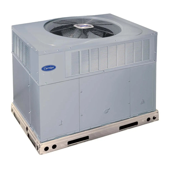
Fig. 1 - - Unit 50EZ- -A
. . . . . . . . . . . . . . . . . . . .
. . . . . . . . . . . . . . . . . . . . . . . . . . . . . . . . .
. . . . . . . . . . . . . . . . . . . . . . . . . . . . .
. . . . . . . . . . . . . . . . . . . . . . . . . . . . . .
. . . . . . . . . . . . . . . . . . . . . . . . . . . . . . . .
. . . . . . . . . . . . . . . . . . . . . . . . . . . . . . . . . . . .
. . . . . . . . . . . . . . . . . . . . . . . . . . . . . . . . .
. . . . . . . . . . . . . . . . . . . . . . . . . . .
. . . . . . . . . . . . .
. . . . . . . . . . . . . . . . . . . . . . . . . . . . . . . .
. . . . . . . . . . . . . . . . . . . . . . . . . . . .
. . . . . . . . . . . . . . . . . . . . . . . . .
. . . . . . . . . . . . . . . . . . . . . . . . . . . . . .
. . . . . . . . . . . . . . . . . . . . . . . . . . . .
A09034
32
32
32
32
. . . . . . . . .
32
32
32
32
. . . .
32
33
33
33
33
33
33
33
.
Advertisement
Table of Contents

Related Manuals for Carrier 50EZ-A30


Summary of Contents for Carrier 50EZ-A30
-
Page 1: Table Of Contents
50EZ---A Comfortt 13 SEER Single ---Packaged Heat Pump System with Puron (R ---410A) Refrigerant Three Phase 2 1/2---5 Nominal Tons (Sizes 30---60) Installation Instructions IMPORTANT: Effective January 1, 2015, all split system and packaged air conditioners must be installed pursuant to applicable regional efficiency standards issued by the Department of Energy. -
Page 2: Introduction
als, be alert to the potential for personal injury. Understand these the downflow panels before rigging and lifting into place. The signal words: DANGER, WARNING, and CAUTION. These panel removal process may require the unit to be on the ground. words are used with the safety- -alert symbol. -
Page 3: Rig And Place Unit
Do not place the unit where water, ice, or snow from an overhang INSPECTION or roof will damage or flood the unit. Do not install the unit on Prior to initial use, and at monthly intervals, all rigging shackles, carpeting or other combustible materials. Slab- -mounted units clevis pins, and straps should be visually inspected for any damage, should be at least 2 in. - Page 4 A150587 Fig. 2 - - 50EZ- -A30- -36 Unit Dimensions...
- Page 5 A150588 Fig. 3 - - 50EZ- -A42- -60 Unit Dimensions...
- Page 6 Dashed lines show cross support location for large basepan units. HVAC unit HVAC unit basepan base rails Sealing Gasket Roofcurb Anchor screw Wood nailer* Flashing field supplied Roofcurb* Insulation (field supplied) Roofing material field supplied Cant strip field supplied SMALL/COMMON CURB A09413 *Provided with roofcurb A09090...
-
Page 7: Rigging/Lifting Of Unit
CAUTION - NOTICE TO RIGGERS PRUDENCE - AVIS AUX MANIPULATEUR ACCESS PANELS MUST BE IN PLACE WHEN RIGGING. PANNEAUX D'ACCES DOIT ÊTRE EN PLACE POUR MANIPULATION. Use top skid as spreader bar. / Utiliser la palette du haut comme barre de répartition DUCTS MINIMUM HEIGHT: 36"... -
Page 8: Converting Horizontal Discharge Units To Downflow (Vertical) Discharge Units
WARNING PERSONAL INJURY HAZARD Failure to follow this warning could result in personal injury or death. For vertical supply and return units, tools or parts could drop into ductwork Install a 90 degree turn in the return ductwork between the unit and the conditioned space. If a 90 degree elbow cannot be installed, then a grille of sufficient strength and density should be installed to prevent objects from falling into the conditioned space. -
Page 9: Provide For Condensate Disposal
Step 6 — Provide for Condensate Disposal High- - Voltage Connections The unit must have a separate electrical service with a NOTE: Ensure that condensate- -water disposal methods comply field- -supplied, waterproof disconnect switch mounted at, or within with local codes, restrictions, and practices. sight from the unit. -
Page 10: Control Voltage Connections
Control Voltage Connections NOTE: If the unit 24V wires do not have a matching receptacle, cut the 24V wires from the electric heater plug, strip the ends, and NOTE: Do not use any type of power- -stealing thermostat. Unit wire nut together to match the schematic connections. If the electric control problems may result. - Page 11 Table 1 – Physical Data - - Unit 50EZ- -A UNIT SIZE 50EZ--- A30 50EZ--- A36 50EZ--- A42 50EZ--- A48 50EZ--- A60 NOMINAL CAPACITY (ton) SHIPPING WEIGHT} (lb) (kg) COMPRESSOR QUANTITY TYPE SCROLL COMPRESSOR REFRIGERANT R---410A Refrigerant (R --- 410A) Quantity (lb) 10.2 10.0 12.3...
- Page 12 A11006 Fig. 11 - - Connection Wiring Schematics - - 208/230- -3- -60...
- Page 13 A11005 Fig. 11 Cont. - - Ladder Wiring Schematics - - 208/230- -3- -60...
- Page 14 A10195 Fig. 12 - - Connection Wiring Diagram 460- -3- -60...
- Page 15 A10195 Fig. 12 Cont. - - Ladder Wiring Diagram 460- -3- -60...
-
Page 16: Pre- -Start- -Up
PRE- - START- - UP position and shuts down when FAN MODE switch is placed in AUTO position. WARNING (2.) Thermostat: When the room temperature rises to a point that is slightly above the cooling control setting of the FIRE, EXPLOSION, ELECTRICAL SHOCK HAZARD thermostat, the thermostat completes the circuit Failure to follow this warning could result in personal injury, between thermostat terminal R to terminals Y, O... -
Page 17: 50Ez- -A Sequence Of Operation
IMPORTANT: Three- -phase, scroll compressors are direction IMPORTANT: When evaluating the refrigerant charge, an oriented. Unit must be checked to ensure proper compressor indicated adjustment to the specified factory charge must always be 3- -phase power lead orientation. If not corrected within 5 minutes, very minimal. -
Page 18: Continuous Fan Operation
shipped loose with vinyl caps and are located in the control box, cooling fan speed and place desired speed tap wire on the near the interface fan board (IFB) (See Fig. 14). “LOW” connection on the interface board (IFB). Verify that static pressure is in the acceptable range for the speed Single Cooling Fan Speed Set-up (Dehumidification tap to be used for dehumidification cooling. - Page 19 INDOOR COIL OUTDOOR COIL TXV in Metering Position HP S Bypass LEGEND P osition HPS – High Pressure Switch LCS – Loss of Charge Switch Accurater ® Metering De vice Arrow indicates direction of flo w C03011 Fig. 13 - - Typical Heat Pump Operation, Cooling Mode HIGH R13 C8 AB A15...
-
Page 26: Defrost Control
Step 3 — Defrost Control WARNING Quiet Shift Quiet Shift is a field- -selectable defrost mode, which will eliminate ELECTRICAL SHOCK HAZARD occasional noise that could be heard at the start of defrost cycle and Failure to follow these warnings could result in personal restarting of heating cycle. -
Page 27: Outdoor Fan
Step 2 — Outdoor Coil, Indoor Coil, and WARNING Condensate Drain Pan Inspect the condenser coil, evaporator coil, and condensate drain ELECTRICAL SHOCK HAZARD pan at least once each year. Failure to follow this warning could result in personal injury The coils are easily cleaned when dry;... - Page 28 A150586 Fig. 16 - - Cooling Charging Table- -Subcooling...
-
Page 29: Electrical Controls And Wiring
Speedup Quiet Defrost interval Pins Shift DIP switches A08020 Fig. 17 - - Defrost Control Step 4 — Electrical Controls and Wiring Inspect and check the electrical controls and wiring annually. Be sure to turn off the electrical power to the unit. Remove access panels (see Fig. -
Page 30: Indoor Airflow
High pressure may be caused by a dirty outdoor coil, failed fan motor, or outdoor air recirculation. To check switch: 1. Turn off all power to unit. 2. Disconnect leads on switch. 3. Apply ohm meter leads across switch. You should have continuity on a good switch. -
Page 31: Liquid Line Filter Drier
Step 13 — System Information repairing refrigerant leaks, replacing refrigerant components such as filter drier, pressure switch, metering device, coil, accumulator, Loss of Charge Switch or reversing valve. The loss of charge switch is a protective device wired into control Synthetic Roof Precautionary Procedure circuit (low voltage). - Page 32 Table 10 – Troubleshooting Chart SYMPTOM CAUSE REMEDY Power failure Call power company Fuse blown or circuit breaker tripped Replace fuse or reset circuit breaker Defective contactor, transformer, or high--pressure, Replace component loss--of--charge or low--pressure switch Compressor and condenser fan will not start. Insufficient line voltage Determine cause and correct Incorrect or faulty wiring...
- Page 33 PURONR (R- -410A) QUICK REFERENCE GUIDE Puron refrigerant operates at 50- -70 percent higher pressures than R- -22. Be sure that servicing equipment and replacement components are designed to operate with Puron Puron refrigerant cylinders are rose colored. Recovery cylinder service pressure rating must be 400 psig, DOT 4BA400 or DOT BW400. Puron systems should be charged with liquid refrigerant.
- Page 34 { Measured at liquid line leaving condenser. Catalog No: 50EZ---12SI Copyright 2015 Carrier Corp. S 7310 W. Morris St. S Indianapolis, IN 46231 Edition Date: 10/15 Manufacturer reserves the right to change, at any time, specifications and designs without notice and without obligations.
Need help?
Do you have a question about the 50EZ-A30 and is the answer not in the manual?
Questions and answers