Table of Contents
Advertisement
Advertisement
Table of Contents

Related Manuals for AEG AC3050B


Summary of Contents for AEG AC3050B
- Page 1 AC3050B Original instructions...
- Page 2 Important! It is essential that you read the instructions in this manual before assembling, operating and maintaining the product. Subject to technical modifications.
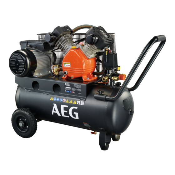
- Page 3 Fig. 1 1 - Air filter assembly x2 2 - Oil cap 3 - On/off switch 4 - Handle 5 - Tank pressure gauge 6 - Regulator pressure gauge 7 - Quick connect coupler 8 - Pressure regulator knob 9 - Pressure relief valve 10 - Rubber foot x2 11 - Drain valve 12 - Wheel x2...
- Page 4 Fig. 6 Fig. 8 1 - Quick connect coupler 2 - Quick connect air fitting 3 - To close (counterclockwise) 4 - Pressure relief valve 5 - Pressure regulator locking ring Fig. 9 1 - Oil cap 2 - Sight glass 3 - Oil level indicator 1 - Quick connect air fitting 2 - Quick coupler...
- Page 5 Fig. 11 Fig. 12 1 - Drain valve 1 - Ring 2 - To close 2 - Pressure relief valve 3 - To open Fig. 13 Fig. 14 1 - Oil drain plug 1 - Reset button Fig. 15 1 - Air filter housing 2 - Air filter 3 - Air filter cover...
- Page 6 TECHNICAL DATA AIR COMPRESSOR AC3050B Rated motor power 2200 W Rated current 9.5 A Air outlets 2 pcs, 6.35mm (1/4”) NITTO style connector/ coupler (suitable for NITTO fitments) Quick connector fitting size 6.35 mm (1/4”) BSP thread Weight 62.5 kg...
- Page 7 AIR COMPRESSOR USE AND CARE Never point any air tool toward yourself or others. Do not operate this air compressor if it does not contain a legible Do not exceed the pressure rating of any component in the warning label. system.
- Page 8 Use the product only for its intended use. Do not alter or modify WARNING the product from the original design or function. Do not connect to power supply until assembly is complete. Failure Always be aware that misuse and improper handling of the to comply could result in accidental starting and possible serious product can cause injury to yourself and others.
- Page 9 INSTALLING AIR FILTERS you avoid damaging the wheel or the air compressor by rolling it over items in its path. See figure 5. Ensure the air compressor is unplugged the power cord is secured Attach one air filter to the cylinder cover on each side. Screw in a from free movement.
- Page 10 The pressure relief valve will automatically release air if the air tank WARNING pressure exceeds the preset maximum. The valve should be checked before each day of use by pulling the ring by hand. Never exceed the air tool’s pressure rating as recommended by 1.
- Page 11 STORAGE the oil is routinely checked for proper levels. 1. Push the power switch to the OFF position to turn off the WARNING compressor. 2. Unplug the compressor. Do not at any time let brake fluids, gasoline, petroleum-based 3. Run the air tool to relieve the air pressure in the hose, then products, penetrating oils, etc., come in contact with plastic parts.
- Page 12 10 m from the spraying area and all explosive vapours. Use only AEG accessories and spare parts. Should components need to be replaced which have not been described, please contact one of our AEG service agents (see our list of guarantee/service addresses).
- Page 13 TROUBLESHOOTING PROBLEM POSSIBLE CAUSE SOLUTION Compressor will not run Loss of power or overheating Check for proper use of extension cord No electrical power Check to be sure unit is plugged in Check fuse/breaker Blown shop/house fuse Replace shop/house blown fuse Shop/house breaker open Reset shop/house breaker, determining why problem happened...
- Page 14 PARTS LIST...
- Page 15 Description Description Description Description Pump assembly 1-31 Spring 13-5 Bolt Elbow exhaust Crankcase 1-32 Washer 13-6 Obturating ring Exhaust Oil plug 1-33 13-7 Cover Elbow exhaust Shaft seal 1-34 Crank shaft 13-8 Capacitance box Unloading pipe Oil glass 1-35 Bearing 13-9 Elbow Oil plug...
- Page 16 CIRCUIT DIAGRAM Motor Current protector 220V-240V INPUT POWER 2200W Aux. Main Pressure Switch winding winding Start Power cable: 1.5 mm² capacitor Working Input power: 2.2 kW capacitor Main winding: 1.0 mm Centrifugal switch Aux. winding: 1.05 mm Start capacitor: 250V/250uf Working capacitor: 450V/40uf...
- Page 19 NITTO is a registered trademark owned by Nitto Kohki Co., Ltd...
- Page 20 Techtronic Industries Australia Pty Ltd 31 Gilby Road, Mount Waverley, VIC 3149 Melbourne, Australia Techtronic Industries N.Z. Limited 2 Landing Drive, Mangere Auckland, 2022, New Zealand AEG is a registered trademark used under 20181105v1 license from AB Electrolux (publ).
Need help?
Do you have a question about the AC3050B and is the answer not in the manual?
Questions and answers