Table of Contents
Advertisement
Issue/Rev. 0.5 (6/11)
Models Included:
T11, I-75
T-20, I-150
T-40
SC-13, SC-13-DI
SD-30, SD-30-DI
SD3-S1
SD3-NF
SF4-NF
SG6-NF
Contents
Section 1 - General Information and Description ....................................................................................Page 2
Description .....................................................................................................................................................Page 2
Suggested Tools and Fixtures ........................................................................................................................Page 2
Disassembly of Model T-11 and I-75 Meters...................................................................................................Page 3
Disassembly of Model T-20, T-40, I-150, SC, SD, SF, and SG Meters ............................................................Page 6
Adjusting Rotor End Clearances ....................................................................................................................Page 9
Section 2 - Clearance Checks ....................................................................................................................Page 12
Blade Tip Toward Housing ..............................................................................................................................Page 13
Rotor to Block .................................................................................................................................................Page 13
Blade Slot .......................................................................................................................................................Page 13
Blade End to Rotor .........................................................................................................................................Page 14
Blade Roller Over Radius Portion of Cam ......................................................................................................Page 14
Section 3 - Meter Repairs ...........................................................................................................................Page 15
Replacing Adjusting Stem Assembly ..............................................................................................................Page 15
Replacing Packing Gland ...............................................................................................................................Page 15
Installing New Rotor .......................................................................................................................................Page 14
Replacing Blade Assembly .............................................................................................................................Page 15
Blade Roller Replacement (T-20, T-40, I-150, SC, SD, SF, and SG Meters Only) ..........................................Page 16
Cam Replacement (T-11 or I-75 Meters Only) ................................................................................................Page 16
Section 4 - Troubleshooting Table .............................................................................................................Page 18
Meter Clearance Record .............................................................................................................................Page 19
Section 5 - Related Publications ...............................................................................................................Page 20
Smith Meter
T-Type Meters
S-Type Meters
The Most Trusted Name In Measurement
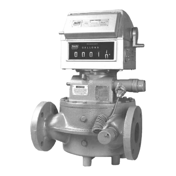
PD Rotary Vane Meter
®
Single-Case Series
Service
Bulletin MN01029
Advertisement
Table of Contents

Related Manuals for FMC Technologies Smith Meter I-75


Summary of Contents for FMC Technologies Smith Meter I-75
-
Page 1: Table Of Contents
Smith Meter PD Rotary Vane Meter ® Single-Case Series Service Issue/Rev. 0.5 (6/11) Bulletin MN01029 Models Included: T11, I-75 T-20, I-150 T-40 SC-13, SC-13-DI SD-30, SD-30-DI SD3-S1 SD3-NF SF4-NF SG6-NF T-Type Meters S-Type Meters Contents Section 1 – General Information and Description ..................Page 2 Description ..............................Page 2 Suggested Tools and Fixtures ........................Page 2 Disassembly of Model T-11 and I-75 Meters....................Page 3... -
Page 2: Section 1 - General Information And Description
Also, the rotor FMC Technologies Measurement Solutions, Inc. pro- and jackshaft gear assemblies have been changed to vides a meter variation with tungsten carbide trim to hardened stainless steel. -
Page 3: Suggested Tools And Fixtures
Section 1 – General Information and Description (continued) Suggested Tools and Fixtures • Before replacing cover, apply a thin layer of seal- ant (Master Gasket by Loctite is recommended) around the perimeter of the cover to form a seal In addition to ordinary hand tools, the following tools and between the housing and the cover. - Page 4 Section 1 – General Information and Description (continued) 4. Turn rotor upside down and place on a wooden block • When replacing the thrust bearing, indent side of thrust bearing plates must face outward from or equivalent. retainer and balls, Figure 8. •...
- Page 5 Section 1 – General Information and Description (continued) 3. The blades are matched to their own slots during Rotor Disassembly manufacturing. Therefore, before removing blades 1. Remove clamps and blade blocks, Figure 11, from from the rotor, the blades and rotor slots must be rotor assembly.
-
Page 6: Disassembly Of Model T-20, T-40, I-150, Sc, Sd, Sf, And Sg Meters
Section 1 – General Information and Description (continued) Figure 16 6. Figure 16 shows the rotor shaft inside the rotor body. • The rotor body, shaft, and rotor cover (removed in Figure 12) are factory-assembled and matched as one integral piece. Therefore, if any one of these items is damaged, the complete assembly (body, Figure 18 shaft, and cover) must be replaced. - Page 7 Section 1 – General Information and Description (continued) Figure 21 Figure 20 4. When rotor assembly is removed from the housing, turn it upside down and place it on a wooden block or metal plate. • The wooden block or plate must have a clearance hole in the center for the shaft and must be high enough to allow the shaft to clear the table.
- Page 8 Section 1 – General Information and Description (continued) Standard Rotor Standard Blade Bearing Bearing and Pin Tungsten Carbide Tungsten Carbide Rotor Blade Bearing Bearing and Pin Figure 27 Figure 25 next level assemblies (rotor gear plate or rotor subassembly) be procured with bearings already installed, or capabilities must permit epoxying bearings in precise alignment.
-
Page 9: Adjusting Rotor End Clearances
Section 1 – General Information and Description (continued) Adjusting Rotor End Clearances Caution: Before any adjustments can be made, the meter must be removed from the line or drained. T-11 or I-75 Meters Only The T-11 or I-75 Meter can have the rotor and adjust- ments made without removing the calibrator on top of the meter. - Page 10 Section 1 – General Information and Description (continued) Figure 37 Figure 37A 2. Figure 38 illustrates the meter with the adapter re- Figure 35 moved. The arrow points to the locking mechanism 3. With rotor revolving, turn Allen wrench clockwise for the rotor end adjustment and the Jack Shaft gear.
- Page 11 Section 1 – General Information and Description (continued) 3. Remove the Adjusting Screw. Clean and apply LOC- TITE 242. Figure 40 indicates where the LOCTITE is to be applied. 4. Figure 41 is a photo of the locking mechanism. SCREW (TOP), ADJUSTING CAP (MIDDLE) (NOTE: the arrows point to a gasket at the base of the Adjust- ing Cap and a brass gasket in the top of the Adjusting Cap.
-
Page 12: Section 2 - Clearance Checks
Section 2 – Clearance Checks Figure 46 Figure 47 7. Install the screw. Hold the Adjusting Cap with a ¾” wrench while tightening the screw with a 5/32" Allen only as a guide in determining whether or not a part Head wrench (Figure 46). -
Page 13: Blade Tip Toward Housing
Section 2 – Clearance Checks (continued) Attach a spider, Figure 47, to top of meter housing so that the rotor assembly is centered in the housing and free to rotate. See Suggested Tools, Pages 2 and 3. Method No. 2: If spider is not available, turn the adjusting screw on bottom of housing clockwise until rotor assembly meets friction and is hard to turn. -
Page 14: Blade End To Rotor
Section 2 – Clearance Checks (continued) Blade End to Rotor Blade Roller Over Radius Portion of Cam This check can be made with the rotor assembly in the 1. Rotate rotor until a blade is in Position No. 1 as shown meter housing or situated on a flat, even surface. -
Page 15: Section 3 - Meter Repairs
Section 3 – Meter Repairs Replacing Adjusting Stem Assembly 5. Install new packing gland and reassembled items removed in Steps 1, 2, and 3. The adjusting stem assembly may be replaced as a unit • Replace packing gland gasket, Figure 56, if required. or it may be disassembled and repaired. -
Page 16: Blade Roller Replacement (T-20, T-40, I-150, Sc, Sd, Sf, And Sg Meters Only)
Section 3 – Meter Repairs (continued) Cam Replacement (T-11 or I-75 Meters Only) Disassemble meter following Steps 1 through 4 under Disassembly of Model T-11 and I-75 Meters, Page 2 and 3, and proceed as follows: 1. With rotor assembly removed, unscrew hold-down screws and lift cam straight up from housing center hub, Figure 59. - Page 17 Section 3 – Meter Repairs (continued) 7. If fixture does not pass through cleanly, see Figure 61, then remove hold-down screws and cam. Check housing for distortion in area of dwell on cam. 8. If fixture passes, but a gap is noticed between the fixture and cam face: a.
-
Page 18: Section 4 - Troubleshooting Table
Section 4 – Troubleshooting Table Problem Cause Remedy Air passing through meter. Check air eliminator. Over-registration (register- ing more volume than pass- Calibrator out of adjustment. Readjust calibrator. See MN01028, Pg. 4. ing through meter). Leaky valve in prover system (during Repair prover valve and rerun test. -
Page 19: Meter Clearance Record
Issue/Rev. 0.5 (6/11) MN01029 • Page 19... -
Page 20: Section 5 - Related Publications
Beijing, China +86 (10) 6500 2251 Buenos Aires, Argentina +54 (11) 4312 4736 Singapore, +65 6861 3011 Burnham, England +44 (1628) 603205 Visit our website at www.fmctechnologies.com/measurementsolutions Printed in U.S.A. © 6/11 FMC Technologies Measurement Solutions, Inc. All rights reserved. MN01029 Issue/Rev. 0.5 (6/11)
Need help?
Do you have a question about the Smith Meter I-75 and is the answer not in the manual?
Questions and answers