FMC Technologies Smith Meter AccuLoad II Operator's Manual
Electronic preset delivery system rbu
Hide thumbs
Also See for Smith Meter AccuLoad II:
- Programming workbook (63 pages) ,
- Operator's manual (57 pages)

Subscribe to Our Youtube Channel
Related Manuals for FMC Technologies Smith Meter AccuLoad II


Summary of Contents for FMC Technologies Smith Meter AccuLoad II
- Page 1 Electronic Preset Delivery System AccuLoad II - RBU Operator Guide Issue/Rev. 0.3 (8/97) Bulletin MN06065 Smith Meter Inc. The Most Trusted Name In Measurement...
-
Page 2: Table Of Contents
Table of Contents Section I - Introduction ............................1 Product Description............................1 How To Use This Manual..........................2 Before Beginning Operations ..........................3 Section II - Operations............................4 Run Mode.................................4 Keypad Functions............................4 Overview ...............................5 Remote Start/Stop............................5 Quad OPV..............................5 Additive Monitoring ............................5 Additive Injector Selection..........................6 Stand-alone Mode ............................6 Standby Mode ...............................7 Communications EIA - 232 ..........................7 Communications EIA - 485 ..........................7... - Page 3 Table of Contents Dynamic Display Reference (Products) ......................19 00 - Temperature............................19 01 - API............................... 19 02 - Product Flow Rate (Units/Min) ......................19 03 - Product Flow Rate (Units/Hour) ......................19 04 - Reference Density..........................19 05 - Relative Density ........................... 19 06 - Density..............................
- Page 4 Table of Contents 17 - Gross Batch Volume (Product 3) ......................24 18 - Gross at Standard Temperature Batch Volume (Product 3) ..............24 19 - Net Batch Volume (Product 3) ......................24 20 - Mass Batch Totals (Product 3) ......................25 21 - Raw Batch Volume (Product 4)......................
- Page 5 Table of Contents 25 - Additive Injector 6 Transaction Volume....................29 26 - Additive Injector 7 Transaction Volume....................29 27 - Additive Injector 8 Transaction Volume....................29 28 - Raw Transaction Volume........................29 29 - Gross Transaction Volume ........................29 30 - Gross at Standard Temperature Transaction Volume ................
-
Page 6: Section I - Introduction
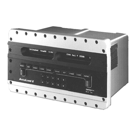
Section I - Introduction Product Description • Relative Density at Reference • Current Pressure and Vapor Pressure The Smith AccuLoad II-RBU is a microprocessor • Current Meter Factor based electronic instrument/in-line blender delivery • Current CTL system designed to simultaneously control the •... -
Page 7: How To Use This Manual
Section I - Introduction • Significant communication capability is available from AccuLoad II, if so programmed, will automatically the standard AccuLoad II. The instrument is pro- adjust the final trip point of the batch (Preset). grammable for Polling, Polling and Authorization or complete Remote Control via communications. -
Page 8: Before Beginning Operations
Section I - Introduction The AccuLoad II contains two side by side one line Before Beginning Operations by 24 character, 5X7 dot matrix vacuum fluorescent Before actual operations begin, it is essential that displays. When powered on, both displays will illumi- valid entries are made for all program codes. -
Page 9: Section Ii - Operations
Section I - Introduction Run Mode All preset and control operations can be performed either locally through the keypad or through commu- This is the normal driver controlled mode of operation nications. The operation described in this section is where a preset volume of product is preset into Ac- based on AccuLoad II being operated locally through cuLoad II. -
Page 10: Overview
Section II - Operations Overview The operator can then press "START" and continue the batch. If program code 209 is programmed to The "RUN" mode permits the operator to select the disable the time-out, the display will read: recipe, the preset volume and start the preset volume or to observe the dynamic variables such as flow rate, temperature, volume correction factors, trans- Press Start to Continue... -
Page 11: Additive Injector Selection
Section II - Operations Additive Injector Selection Where: Midgrade = The programmed recipe name. Stand-alone Mode = The recipe number selected by the When the AccuLoad II Ratio Blender is in the Stand- operator. alone mode of operation the additive selection can be programmed to be either automatic or manual, de- 4. -
Page 12: Standby Mode
Section II - Operations Note: Any additive output that has a zero entry programmed in its Communications Time-out must have a value corresponding program code will always be disabled and will not other than "000" programmed into it. appear in the selection process. Communications Alarm Mode... -
Page 13: Local Ticket Printer
Section II - Operations Zero Standby Mode. The driver or operator is required to enter a recipe number (1 through 24) and press "ENTER". The left- Two Standby and Communication Alarm. hand display will indicate the recipe name and num- ber that has been selected. - Page 14 Section II - Operations A predetermined volume to be loaded is entered at At this time, the left-hand display becomes a counter. the keypad. AccuLoad II will check this volume The first through the sixth positions become an up- against the Maximum Preset Volume (program code counter (delivery counter).
- Page 15 Section II - Operations The right-hand display displays the recipe that is be- ing loaded. When the products being loaded reach a predetermined (First Stage Trip code 207 in the Press Start to Continue Product Directory) value, the valve is signaled to close.
-
Page 16: Remote Ticket Printer (Print Key)
Section II - Operations After power returns the right display will display the 2. At the end of the batch the AccuLoad II display recipe that was being loaded: will alternate between: Midgrade 1000 Gal P 1000 After "START" is pressed the batch will continue from the point of the power failure. -
Page 17: Section Iii - Dynamic Displays
Section II - Operations Dynamic Displays Number of This section describes informational displays which Directory Description Digits can be viewed while in the Run Mode. These dis- Number for Entry plays are "dynamic" in the sense that the displayed values reflect current actual conditions and will con- System tinuously update while being viewed. -
Page 18: Keypad Functions
Section III - Dynamic Displays Keypad Functions The dynamic display from the systems display that is represented by 012 is: The pushbuttons on the keypad perform the follow- ing functions when accessing the dynamic displays: Add 8 = 0000121555 Oz Description 1. - Page 19 Section III - Dynamic Displays To access the dynamic displays for the recipes the 5. Press “ENTER”. operator must enter a five digit number (i.e., 50100). Net Total 000000000 The first digit represents the recipe dynamic dis- plays. The second and third digits represent the recipe (01 through 24) displays that are to be dis- 6.
- Page 20 Section III - Dynamic Displays 3. “ENTER 01” for the dynamic display number, 5. Press “ENTER”. the display will read: Gst Batch 998.28 Batch 2 Dyn Display01 6. To revert back to the preset display, press then the display will automatically switch to: “CLEAR”.
-
Page 21: Dynamic Display Reference (System)
Section III - Dynamic Displays Dynamic Display Reference (System) 04 - Current Products The products that are currently being loaded will be displayed. 00 - Time & Date The current time and date will be displayed. Current Products 1 2 3 4 9:20:05 AM 10-10-92 05 - Injector #1 Volume The additive injector #1 non-resettable totals will be... -
Page 22: Injector #5 Volume
Section III - Dynamic Displays 09 - Injector #5 Volume 15 - Injector #3 Pulse Rate (Units/Injection) The additive injector #5 non-resettable totals will be The additive injector #3 pulse rate will be displayed. displayed. Inj3 Prg 40 Cal 39.20 Add 5 = 000005850 Oz 16 - Injector #4 Pulse Rate (Units/Injection) -
Page 23: Flow Rate For Each Product
Section III - Dynamic Displays 22 - Flow Rate for Each Product 82 - Relay Status The current flow rate (units as programmed) for The status of the AC relays seven through twelve each of the products being loaded will be displayed. will be displayed. -
Page 24: Dynamic Display Reference (Products)
Section III - Dynamic Displays Dynamic Display Reference (Products) Where: Hi = High Flow Lo = Low Flow Mn = Minimum Flow 00 - Temperature Q1 = Step 1 of shut-down The current temperature of the product requested Q2 = Step 2 of shut-down being measured and used for compensation will be Q3 = Step 3 of shut-down displayed. -
Page 25: Meter Factor
Section III - Dynamic Displays 08 - Meter Factor 13 - Gross @ Standard Temperature Non- resettable Volumes The current meter factor of the product requested being used to correct the raw volume to the gross The gross @ standard temperature non-resettable volume will be displayed. -
Page 26: Load Average Density
Section III - Dynamic Displays 18 - Load Average Density 24 - Mass Transaction The load average density of the product requested The mass that is currently being loaded of the prod- for the current transaction will be displayed. uct requested will be displayed. Ld Avg Den Mas Transaction 19 - Load Average Meter Factor... -
Page 27: Dynamic Display Reference (Recipe)
Section III - Dynamic Displays Dynamic Display Reference (Recipe) 03 - Gross @ Standard Temperature Non- resettable Volumes The gross at standard temperature non-resettable 00 - Recipe Name total for the recipe selected will be displayed. The programmed name for the recipe requested will be displayed. -
Page 28: Dynamic Display Reference (Batch)
Section III - Dynamic Displays Dynamic Display Reference (Batch) 05 - Mass Batch Totals The mass total for the recipe requested for that batch will be displayed. 00 - Product Delivered The product delivered for the batch requested will be displayed. -
Page 29: Mass Batch Totals (Product 1)
Section III - Dynamic Displays 10 - Mass Batch Totals (Product 1) 15 - Mass Batch Totals (Product 2) The mass total for product 1 of the recipe requested The mass total for product 2 of the recipe requested for that batch will be displayed. for that batch will be displayed. -
Page 30: Mass Batch Totals (Product 3)
Section III - Dynamic Displays 20 - Mass Batch Totals (Product 3) 25 - Mass Batch Totals (Product 4) The mass total for product 3 of the recipe requested The mass total for product 4 of the recipe requested for that batch will be displayed. for that batch will be displayed. -
Page 31: Recipe Load Average Density
Section III - Dynamic Displays 31 - Recipe Load Average Density 37 - Additive 2 Batch Volume The load average density of the recipe loaded for The total for additive 2 of the recipe requested for this batch will be displayed. that batch will be displayed. -
Page 32: Additive 8 Batch Volume
Section III - Dynamic Displays 43 - Additive 8 Batch Volume 04 - Mass Transaction Totals (Product 1) The total for additive 8 of the recipe requested for The mass total for the last transaction will be dis- that batch will be displayed. played. -
Page 33: Mass Transaction Totals (Product 2)
Section III - Dynamic Displays 09 - Mass Transaction Totals (Product 2) 15 - Raw Transaction Volume (Product 4) The mass total for the last transaction will be dis- The raw total for the last transaction will be dis- played. played. -
Page 34: Additive Injector 6 Transaction Volume
Section III - Dynamic Displays 21 - Additive Injector 2 Transaction Volume 26 - Additive Injector 7 Transaction Volume The total for additive injector 2 for the last transac- The total for additive injector 7 for the last transac- tion will be displayed. tion will be displayed. -
Page 35: Gross At Standard Temperature And Pressure Transaction Volume
Section III - Dynamic Displays 31 - Gross at Standard Temperature and Pressure Transaction Volume The gross at standard temperature and pressure total for the last transaction will be displayed. Net Trans 499.56 32 - Mass Transaction Totals The mass total for the last transaction will be dis- played. -
Page 36: Section Iv - Program Mode
Section IV - Program Mode Keypad Data Entry These subdirectories are then subdivided into three sections; low security, high-security and special high- All programming information is entered via the security. Under program protection are the codes that keypad or through communications. This document are low security items or those which do not affect will describe information being entered via the key- volume accuracy such as: the status of the various... - Page 37 Section IV - Program Mode Under the special high-security mode of protection ‘0’ - ‘9’ Used to enter the access code, program are codes whose use may be sensitive under various codes and data entries. Weights and Measures agencies' guidelines or affect volume accuracy.
-
Page 38: Entry To Main Directories
Section IV - Program Mode Entry to Main Directories Left display: 1. Close the Program Mode contact (unless al- Program Mode-Critical=ON ready permanently wired closed). This will pro- vide the first step for access to program codes with a second digit of zero through three. Right display: Note: Weights &... - Page 39 Section IV - Program Mode Left display: Right display: ** Error Press Clear ** Program Mode Right display: 3. Press “SET” again and the next main directory will be displayed: Enter Access Code Left display: Press “CLEAR” the display will return to "READY". Product 2 Directories Left display: Right display:...
-
Page 40: Program Subdirectory Selection
Section IV - Program Mode Program Subdirectory Selection 6. Enter the new directory number (i.e., 400). Once in the Program Mode of the main directory the Enter Dir or Program 400 subdirectory can be accessed either by their three digit code or by pressing “SET” twice, which will en- ter the instrument into the first program subdirectory. -
Page 41: Exiting A Subdirectory
Section IV - Program Mode Exiting A Subdirectory 4. If another code is required, press “CLEAR” the following display will appear: To exit a subdirectory and to enter the next subdi- rectory, follow the steps listed below: 100 General Purpose Dir 1. -
Page 42: Sequential Code Selection
Section IV - Program Mode 4. Press “ENTER”. 4. Press “SET” again ... 201 Low Flow Amount 109 17:24 Mil Time 5. To access another code in the same directory, 5. Press “SET” again ... press “CLEAR” to get back to the directory. 110 08-23-92 Date 200 Flow Control Dir Etc... -
Page 43: Exiting Program Mode
Section IV - Program Mode Exiting Program Mode 4. Press “ENTER”. To return to the Run Mode, either open the Program Left display: Mode contact and press “SET” or follow the steps listed below. The steps are broken down into two di- Press Enter to Exit visions, the first being if in the main directories one or two and the second being if in the last main di-... -
Page 44: Changing Program Code Parameters
Section IV - Program Mode Changing Program Code Parameters 4. After the data is stored the display will then read: The program codes represent parameters that can be changed to either enhance the performance of 205 0450 High Flow Rate AccuLoad II or can be changed because of applica- tion changes. -
Page 45: Alphanumeric Data
Section IV - Program Mode Alphanumeric Data 3. To add the description "Unleaded" as the Prod- uct message press "4", this will advance the The codes that require alphanumeric data entered in blocks of characters to "A". them are the codes that will display Product Mes- sages, Prompt Messages or Permissive Messages on the displays of AccuLoad II or will provide infor- 180 A<... - Page 46 Section IV - Program Mode 11. Press "1" to move the cursor to the next posi- 16. Advance the arrow (Press "1") until only the tion. message is displayed. The arrow will wrap if "1" is continued to be pressed. 180 Un <...
-
Page 47: Viewing The Help Messages
Section IV - Program Mode Viewing the Help Messages 2. To view the “Help Message” press the “PRINT” key. The message will scroll across the display. The AccuLoad II features unique "Help Messages" that allow the operator to have at his fingertips the Select method of Transaction ability to review what is required or what the options are for an individual program code by simply press-... -
Page 48: Section V - Program Codes
Section V - Program Codes System Configuration Directory Code Description System Configuration Directory Number of Products Number of Additive Injectors A/C Output Relay 1 Terminals 89 & 90 A/C Output Relay 2 Terminals 91 & 92 A/C Output Relay 3 Terminals 93 & 94 A/C Output Relay 4 Terminals 95 &... - Page 49 Section V - Program Codes Code Description A/C Input 10 Terminals 110 & 112 A/C Input 11 Terminals 111 & 112 A/C Input 12 Terminals 75 & 76 RTD #1 Terminals 14, 15, 16, & 17 RTD #2 Terminals 62, 63, 64 & 65 4-20 Channel #1 Terminals 19 &...
- Page 50 Section V - Program Codes Code Description Set Date Dynamic Display Time-out 112-139 Unassigned at Present Protection of Program Codes 180-189 Local Mode Alarm Clearing Decimal or Comma Selection Alarm Relay Run & Ready Mode Initialization Note: This code applies to RBU-05 and above firmware. Ready/Run Mode Clearable Alarms Selection Note: This code applies to RBU-08 and above firmware.
- Page 51 Section V - Program Codes Code Description Valve Delay to Open Zero Flow Alarm Note: This code applies to RBU-08 and above firmware. 213-239 Unassigned at Present Protection of Program Codes 280-289 241-279 Unassigned at Present Clean Line Product Clean Line Volume Clean Line Alarm Limit Ratio Adjustment Factor Ratio Adjustment Timer...
- Page 52 Section V - Program Codes Code Description Combinated Pulse Output Note: This code applies to RBU-02 and above firmware. Combinated Pulse Output Resolution Note: This code applies to RBU-02 and above firmware. Combinated Pulse Output Maximum Frequency Note: This code applies to RBU-02 and above firmware. Resolution of Volumetric Totals on Printed Report Note: This code applies to RBU-08 and above firmware.
- Page 53 Section V - Program Codes Code Description Injector 6 Non-resettable Volume Injector 7 Non-resettable Volume Injector 8 Non-resettable Volume Local Storage Transactions 610-639 Unassigned at Present Protection of Program Codes 680-689 641-699 Unassigned at Present System Communication Directory EIA-232 Communication Type EIA-232 Communication Control EIA-232 Baud Rate EIA-232 Data Format...
- Page 54 Section V - Program Codes Code Description Delivery Report Display Note: This code applies to RBU-01 and above firmware. 725-739 Unassigned at Present Protection of Program Codes 780-789 Communication Link Programming Communications Time-out Communications Alarm Mode Prompt Time-out Prompt Data Entry #1 Prompt Data Entry #2 Prompt Data Entry #3 Prompt Data Entry #4...
- Page 55 Section V - Program Codes Code Description System Input/Output Directory Additive Injector Stop Additive Injector Stop Volume Additive Injector Output Manual/Auto Additive Injector Selection Restart After Valve Power Restored Valve Power Sense Permissive Message Permissive #1 Permissive #1 Message Restart After Permissive #1 Met Prompt Message Permissive #2 Permissive #2 Message...
- Page 56 Section V - Program Codes Code Description Additive Injector #4 Volume per Cycle Additive Injector #5 Feedback Additive Injector #5 Volume per Cycle Additive Injector #6 Feedback Additive Injector #6 Volume per Cycle Additive Injector #7 Feedback Additive Injector #7 Volume per Cycle Additive Injector #8 Feedback Additive Injector #8 Volume per Cycle Injector Units...
- Page 57 Section V - Program Codes Code Description System Diagnostic Directory Diagnostic Display Test Diagnostic Keypad Test Diagnostic RTD #1 & #2 Test Diagnostic 4-20 mA Channel 1 & 3 Diagnostic 4-20 mA Channel 2 & 4 Diagnostic Internal Temperature Diagnostic Power Supply Test Diagnostic Firmware Version Diagnostic AccuLoad II Model Number Diagnostic ACM Model Number...
- Page 58 Section V - Program Codes Code Description Diagnostic High-Speed Prover Product 2 Diagnostic High-Speed Prover Product 3 Diagnostic High-Speed Prover Product 4 Diagnostic Pulse Out 1 Test Diagnostic Pulse Out 2 Test Diagnostic Pulse Out 3 Test Diagnostic Pulse Out 4 Test Clear Local Storage Diagnostic Contact Output Clear Configurable Report...
-
Page 59: Product Program Codes
Section V - Program Codes Product Program Codes Code Description Product General Purpose Directory 101-139 Unassigned at Present Protection of Program Codes 180-189 Product Selection 142-179 Unassigned at Present Product Message 181-199 Unassigned at Present Product Flow Control Directory Excess Flow Rate Overrun Alarm Limit Minimum Flow Rate High Flow Rate... - Page 60 Section V - Program Codes Code Description Flow Rate for Meter Factor #1 Meter Factor #1 Flow Rate for Meter Factor #2 Meter Factor #2 Flow Rate for Meter Factor #3 Meter Factor #3 Flow Rate for Meter Factor #4 Meter Factor #4 Meter Factor % Change/Deg.
- Page 61 Section V - Program Codes Code Description High Density Alarm 449-499 Unassigned at Present Product Pressure Directory Minimum Back Pressure Flow Rate Setting Differential Pressure Minimum Back Pressure Flow Rate Timer Setting BP Reduction Low Pressure Alarm High Pressure Alarm 507-539 Unassigned at Present Protection of Program Codes 580-589...
- Page 62 Section V - Program Codes Code Description Protection of Program Codes 680-689 641-699 Unassigned at Present Communications Directory HM Classification for Printout HM Classification for Printout HM Classification for Printout HM Classification for Printout 705-739 Unassigned at Present Protection of Program Codes 780-789 741-799 Unassigned at Present Product Inputs &...
-
Page 63: Recipe Program Codes
Section V - Program Codes Recipe Program Codes Code Description __00 Blend Recipe #__ Directory __01 Blend Recipe __02 Blend Recipe Name __03 Recipe Raw Non-resettable Volume __04 Recipe Gross Non-resettable Volume __05 Recipe Gross at Standard Temp. Non-resettable Volume __06 Recipe Net Non-resettable Volume __07... - Page 64 Section V - Program Codes Code Description __55 Recipe Correction Factor __80 Clean Line Deduct __81 Additive Injector Pulser No. 1 __82 Additive Injector Pulser No. 2 __83 Additive Injector Pulser No. 3 __84 Additive Injector Pulser No. 4 __85 Additive Injector Pulser No.
-
Page 65: Section Vi - Index
Section VI - Index Load Average Density (Product 3) • 27 Load Average Density (Product 4) • 27 Load Average Temperature (Product 1) • 26 Additive injector feedback • 6 Load Average Temperature (Product 2) • 26 Additive Injector Selection • 7 Load Average Temperature (Product 3) •... - Page 66 Section VI - Index Dynamic Display Reference (Recipe) • 23 Net Transaction Volume (Product 4) • 29 Gross @ Standard Temperature Non-resettable Raw Transaction Volume (Product 1) • 28 Volumes • 23 Raw Transaction Volume (Product 2) • 28 Gross Non-resettable Volumes • 23 Raw Transaction Volume (Product 3) •...
- Page 67 Section VI - Index Main directories • 32 Security • 3 Product 1 • 32 high-security • 3 Product 2 • 32 Program Codes • 3 Product 3 • 32 Weights and Measures • 3 Product 4 • 32 Special high-security • 32 Recipe •...
-
Page 68: Section Vii - Related Publications
Section VII - Related Publications The following literature can be obtained from the Smith Meter Literature Department. Please reference the appro- priate bulletin number and title when ordering. Smith Meter Inc. 1602 Wagner Avenue P.O. Box 10428 Erie, Pennsylvania 16514 AccuLoad II-RBU Specifications ............................ - Page 69 The specifications contained herein are subject to change without notice and any user of said specifications should verify from the manufacturer that the specifications are currently in effect. Otherwise, the manufacturer assumes no responsibility for the use of specifications which may have been changed and are no longer in effect. Headquarters 1602 Wagner Ave., P.O.
Need help?
Do you have a question about the Smith Meter AccuLoad II and is the answer not in the manual?
Questions and answers