Advertisement
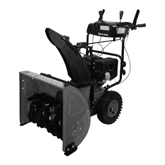
24" 2-STAGE GASOLINE SNOW BLOWER
WITH ELECTRIC START
MODEL: KCG-2421GE
Read this manual. Do not attempt to operate the snow blower until you have read and understood
the safety, operation, and maintenance instructions in this manual.
INSTRUCTION MANUAL
COPYRIGHT © 2018 ALL RIGHTS RESERVED BY KING CANADA TOOLS INC.
Advertisement
Table of Contents

Related Manuals for King Canada Power Force KCG-2421GE

Summary of Contents for King Canada Power Force KCG-2421GE
-
Page 1: Instruction Manual
MODEL: KCG-2421GE Read this manual. Do not attempt to operate the snow blower until you have read and understood the safety, operation, and maintenance instructions in this manual. INSTRUCTION MANUAL COPYRIGHT © 2018 ALL RIGHTS RESERVED BY KING CANADA TOOLS INC. -
Page 2: Warranty And Service Information
LIMITED TOOL WARRANTY KING CANADA makes every effort to ensure that this product meets high quality and durability standards. KING CANADA warrants to the original retail consumer a 1-year limited warranty as of the date the product was purchased at retail and that each product is free from defects in materials. - Page 3 BASIC & SPECIFIC SAFETY PRECAUTIONS FOR GAS ENGINES BASIC SAFETY INFORMATION RISK OF BREATHING - INHALATION HAZARD EXHAUST FUMES ARE DANGEROUS Operate engine in clean, dry, well ventilated area. Never operate unit •Never operate the engine in a closed area or it may cause in enclosed areas such as garages, basements, storage, sheds, or in unconsciensness and death within a short time.
-
Page 4: Maintenance
• Use only accessories recommended by King Canada. • Use a grounded “three-wire” extension cord and receptacle for all machines with electric start engines. - Page 5 GETTING TO KNOW YOUR GASOLINE SNOW BLOWER 1. Auger housing 11. Engine spark plug 21. Oil gauge dipstick 2. Snow clearing stick 12. Muffler 22. Oil drain bolt 3. Discharge chute 13. 13” Wheels 23. Fuel On/Shut-off Valve 4. Discharge chute adjustable deflector 14.
- Page 6 ASSEMBLY ASSEMBLY Your snow blower will require some assembly. Please complete the following steps before using the snow blower. WARNING: This snow blower is heavy. Assembly procedures may require lifting equipment or the help of another person. INSTALLING UPPER HANDLE 1) Install upper handle assembly (A) Fig.1 to the lower support (B) using 4 T-bolts, curved washers and lock knobs (C).
-
Page 7: Engine Fuel Level
ASSEMBLY & INITIAL SET-UP BEFORE OPERATION ASSEMBLY INSTALLING AND ADJUSTING SKID SHOES 1) Loosely install the skid shoes (A) Fig.5 using carriage bolts and hex. nuts (B), install one on each side of the auger housing as shown. Make sure the skid shoe tip faces out. -
Page 8: Engine Operation
ENGINE OPERATION ENGINE OPERATION ENGINE CONTROLS 1) Engine Key Switch (A) Fig.9. The engine key switch enables and disables the ignition system. The engine can’t be turned on without the engine key switch installed in the engine. Pulling the engine key switch out of the engine will stop the engine. 2) Fuel On/Shut-off Valve (B) Fig.9. -
Page 9: Snow Blower Operation
SNOW BLOWER OPERATION AUGER AND DRIVE CONTROLS 1) To engage the auger (blades), press down on the auger control lever (A) Fig.11 (left side handle). 2) To engage the drive, press down on the drive control lever (B) (right side handle). The snow blower should start moving in the direction and speed for the respective setting on the drive speed/gear control. -
Page 10: Storage And Maintenance
STORAGE & MAINTENANCE STORAGE & MAINTENANCE Engine storage guidelines If you plan on storing your engine/snow blower for an extended period of time, the following steps should be followed: 1) Add fuel stabilizer to fuel tank to minimize the formation of fuel gum deposits during storage. -
Page 11: Snow Blower Maintenance
SNOW BLOWER MAINTENANCE CLEARING RESTRICTIONS- AUGER OR IMPELLER JAMS WARNING! The auger and impeller rotate at fast speeds which can cause harm or even amputation. Even if you do not see the auger or impeller rotating, it may start at any time if the engine is running. WARNING! DO NOT try to clear jams with your hands or feet. - Page 12 SNOW BLOWER MAINTENANCE AUGER BELT REMOVAL continued... 3) Loosen the belt guide pin hex. bolt (A) Fig.20 (installed on engine crankcase) and rotate the guide pin (B) away from the pulley (C) as shown. Figure 20 4) Left Side - Loosen the 3 nylon hex. nuts (A) Fig.21 attaching the auger housing to the main frame.
- Page 13 ADJUSTING THE SNOW CHUTE GEARS MOD. KCG-2421GE ADJUSTING THE SNOW CHUTE GEARS ON 24” GASOLINE SNOW BLOWER MODEL KCG-2421GE If you find the snow chute crank handle is difficult to turn to adjust the position of the snow chute, an adjustment to the gear tolerance can be made as follows: The swivel gear system tolerance is controlled by the nylon hex.
Need help?
Do you have a question about the Power Force KCG-2421GE and is the answer not in the manual?
Questions and answers