Viking F-1 Technical Data Manual
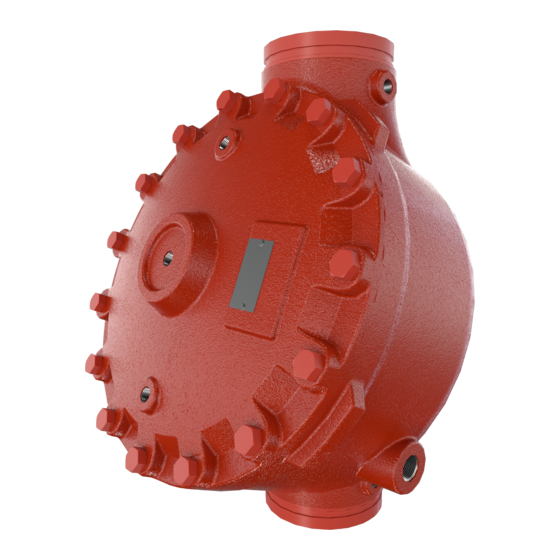
Deluge valve, straight through style 2-1/2” (dn65) - 8” (dn200)
Hide thumbs
Also See for F-1:
- Installation instructions manual (50 pages) ,
- Installation instructions and safety information (52 pages) ,
- Technical data manual (8 pages)
Advertisement
May 7, 2014
The Viking Corporation, 210 N Industrial Park Drive, Hastings MI 49058
Telephone: 269-945-9501 Technical Services: 877-384-5464 Fax: 269-818-1680 Email: techsvcs@vikingcorp.com
1. DESCrIPTIoN
The Viking Model F-1 Deluge Valve is a quick opening, differential diaphragm and flood
valve with one moving mechanism. The Deluge Valve is used to control water flow in
Deluge and Preaction sprinkler systems. The valve is held closed by system water pres-
sure trapped in the priming chamber; keeping the outlet chamber and system piping
dry. In fire conditions, when the releasing system operates, pressure is released from
the priming chamber. The Deluge Valve clapper opens to allow water to flow into the
system piping.
Features:
1.
Field replaceable Diaphragm and Seat Rubbers
2.
Designed for installation in the horizontal or vertical position
3.
Designed to be reset without opening the valve
4.
Compatible with Hydraulic, Pneumatic and/or Electric Release Systems
NoTE: For PArT NuMbErS oF ACCESSorIES, rEFEr To VIkINg LIST PrICE SCHEDuLE.
2. LISTINgS AND APProVALS:
U.L. Listed - Guide No. VLFT & VLJH
C-UL Listed
FM Approved - Deluge Sprinkler Systems, Preaction Sprinkler Systems, Refrigerated Area Sprinkler Systems
American Bureau of Shipping (ABS) - Certificate No. 05-HS502910C-PDA
NYC Department of Buildings - MEA 89-92-E Vol XXXI
CE - Pressure Equipment Directive 97/23/EC
3. TECHNICAL DATA
Specifications:
Maximum Working Water Pressure: 250 PSI (17.4 bar)
Style: Straight through
Connections: See Table 1.
Factory tested: to 500 psi (34.5 bar)
Valve differential: 2:1 (priming chamber to inlet chamber)
Priming chamber supply restriction (required): 0.0625" (1.6 mm)
Color of Valve: Red
Friction loss: Refer to Table 1.
Cv Factor: Refer to Table 1.
Material Standards:
Refer to Figure 2.
ordering Information:
Part Numbers - Refer to Table 1
8" - Manufactured since 2002
4" & 6" - Manufactured since 2003
2-1/2" & 3" - Manufactured since 2004
ACCESSorIES:
Refer to Current VIKING PRICE LIST for Part Numbers.
1.
A Conventional Trim Trim package for use with the Model F-1 Deluge Valve. The trim package includes the VALVE ACCESSORY
PACKAGE and the fittings and nipples shown on the Viking Deluge Valve Conventional Trim Chart Trim Chart for the valve used.
Trim Charts are provided in trim packages and the Viking Engineering and Design Data book. For optional factory assembled
"modular" trim packages, refer to the Viking list price schedule or contact the manufacturer.
2.
A Deluge VALVE ACCESSORY PACKAGE includes required trim components. This package is needed when Viking Trim
Packages are not used.
3.
Auxiliary Components are required for specific valve functions. For complete operating trim requirements, refer to system data
for the system used. System data is provided in the Viking Engineering and Design Data book.
Additional accessories are available and may be required for system operation or supervision. Refer to the system description and
technical data for complete operating trim requirements for the system used.
Form No. F_110802
TECHNICAL DATA
DELugE VALVE, MoDEL F-1
STrAIgHT THrougH STyLE
2-1/2" (DN65) - 8" (DN200)
Viking Technical Data may be found on
The Viking Corporation's Web site at
http://www.vikinggroupinc.com.
The Web site may include a more recent
edition of this Technical Data Page.
Replaces page 218a-j, dated April 15, 2011.
(Updated friction loss and weight values fo DN150 FF)
Deluge Valves 218a
Advertisement
Table of Contents

Related Manuals for Viking F-1


Summary of Contents for Viking F-1
-
Page 1: Specifications
Refer to Current VIKING PRICE LIST for Part Numbers. A Conventional Trim Trim package for use with the Model F-1 Deluge Valve. The trim package includes the VALVE ACCESSORY PACKAGE and the fittings and nipples shown on the Viking Deluge Valve Conventional Trim Chart Trim Chart for the valve used. -
Page 2: Installation
The Model F-1 Deluge Valve is manufactured and listed for use at a maximum Water Working Pressure of 250 PSI (17.2 bar). The valve is factory tested at 500 PSI (34.5 bar). Model F-1 Deluge Valves may be hydrostatically tested at 300 PSI (20.7 bar) and/or 50 PSI (3.4 bar) above the normal Water Working Pressure, for limited periods of time (two hours), for the purpose of acceptance by the... - Page 3 For Deluge Valves equipped with Conventional Deluge Valve Trim, follow steps 1 through 10 (and 11 & 12 if applicable) below. Verify: The system Main Water Supply Control Valve (D.1) is closed and the Deluge Valve is trimmed according to current Viking Trim Charts and schematic drawings for the system used.
- Page 4 DELugE VALVE, MoDEL F-1 TECHNICAL DATA STrAIgHT THrougH STyLE 2-1/2” (DN65) - 8” (DN200) The Viking Corporation, 210 N Industrial Park Drive, Hastings MI 49058 Telephone: 269-945-9501 Technical Services: 877-384-5464 Fax: 269-818-1680 Email: techsvcs@vikingcorp.com Vertical Valve Horizontal Valve Figure 1 - Conventional Trim Components...
-
Page 5: Operation
(Refer to Figure 2.) The Viking Model F-1 Deluge Valve has an inlet chamber, an outlet chamber and a priming chamber. The inlet chamber and outlet chamber are separated from the priming chamber by the clapper (5) and diaphragm (6). -
Page 6: Maintenance
TECHNICAL DATA STrAIgHT THrougH STyLE 2-1/2” (DN65) - 8” (DN200) The Viking Corporation, 210 N Industrial Park Drive, Hastings MI 49058 Telephone: 269-945-9501 Technical Services: 877-384-5464 Fax: 269-818-1680 Email: techsvcs@vikingcorp.com b. Quarterly Main Drain Test Notify the Authority Having Jurisdiction and those in the area affected by the test. -
Page 7: Semi-Annual Maintenance
Prior to reassembly, flush the valve of all foreign matter. To reassemble, reverse disassembly procedure. 7. AVAILAbILITy The Viking Model F-1 Deluge Valve is available through a network of domestic and international distributors. See the Viking Corp. Web site for closest distributor or contact The Viking Corporation. 8. guArANTEES... - Page 8 DELugE VALVE, MoDEL F-1 TECHNICAL DATA STrAIgHT THrougH STyLE 2-1/2” (DN65) - 8” (DN200) The Viking Corporation, 210 N Industrial Park Drive, Hastings MI 49058 Telephone: 269-945-9501 Technical Services: 877-384-5464 Fax: 269-818-1680 Email: techsvcs@vikingcorp.com Figure 2 - replacement Parts PArT NuMbEr No.
- Page 9 STrAIgHT THrougH STyLE 2-1/2” (DN65) - 8” (DN200) The Viking Corporation, 210 N Industrial Park Drive, Hastings MI 49058 Telephone: 269-945-9501 Technical Services: 877-384-5464 Fax: 269-818-1680 Email: techsvcs@vikingcorp.com Maximum Allowable Pilot Heights for Select Equivalent Lengths of Hydraulic Release Piping.
- Page 10 STrAIgHT THrougH STyLE 2-1/2” (DN65) - 8” (DN200) The Viking Corporation, 210 N Industrial Park Drive, Hastings MI 49058 Telephone: 269-945-9501 Technical Services: 877-384-5464 Fax: 269-818-1680 Email: techsvcs@vikingcorp.com Maximum Allowable Pilot Heights for Select Equivalent Lengths of Hydraulic Release Piping.
Need help?
Do you have a question about the F-1 and is the answer not in the manual?
Questions and answers