Table of Contents
Advertisement
SERVICE
M ICROWAV E OV EN
SEF
M ICROWAVE OVEN
M 735
M anual
1. Precaution
2. Statements
3. Operating Instructions
4. Disassembly and Reassembly
400
250
560
120
800W
5. Alignment and Adjustments
0
1
2
60
3
50
4
40
5
30
6
20
7
10
8
9
6. Troubleshooting
M 735
7. Exploded View s and Parts List
8. W iring Diagrams
CON TEN TS
Advertisement
Table of Contents

Related Manuals for Samsung M 735


Summary of Contents for Samsung M 735
- Page 1 M ICROWAVE OVEN M 735 SERVICE M anual M ICROWAV E OV EN CON TEN TS 1. Precaution 2. Statements 3. Operating Instructions 4. Disassembly and Reassembly 800W 5. Alignment and Adjustments 6. Troubleshooting M 735 7. Exploded View s and Parts List...
- Page 2 (5) evidence of dropping or abuse. (e) A Microwave leakage check to verify compliance with the Federal performance standard should be performed on each oven prior to release to the owner. Samsung Electronics...
-
Page 3: Safety Precautions
Also, use only the exact connecting the positive lead; always remove replacements for the following parts: the instrument's ground lead last. Primary and secondary interlock switches, interlock monitor switch. Samsung Electronics... -
Page 4: Special High Voltage Precautions
(Use a screwdriver.) 3. High voltage is maintained within specified limits by close-tolerance, safety-related components and adjustments. If the high voltage exceeds the specified limits, check each of the special components. Fig. 1-1. Discharging the High Voltage Capacitor Samsung Electronics... -
Page 5: Specifications
2. Specifications 2-1 Table of Specifications M 735 POWER SOURCE 230V 50Hz, SINGLE PHASE POWER CONSUM PTION 1300W OUTPUT POWER 120W/ 800W OPERATING FREQUENCY 2450M Hz TIM ER 60 M INUTES COOLING M ETHOD AIR COOLING M AGNETRON OM 75SH(31)ESST... -
Page 6: Operating Instructions
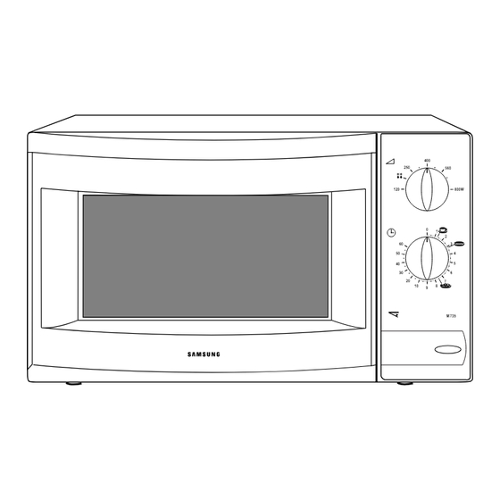
3. Operating Instructions 3-1 Control Panel 800W M 735 Samsung Electronics... -
Page 7: Checking That Your Oven Is Operating Correctly
Operating Instruction 3-2 Features & External View s Ventilation Slot Light Door Safety Interlock Holes 800W Control Panel Door Latches M 735 Open Door Push Button Glass Tray Guide Roller 800W M 735 200mm 357mm 489mm 356mm 3-3 Checking That Your Oven is Operating Correctly NOTE: The oven must be plugged into an appropriate wall socket. -
Page 8: Variable Pow Er Cooking Chart
Operating Instruction 3-4 Variable Pow er Cooking Chart Operation: OUTPUT Set the COOKING POWER CONTROL POW ER LEVEL M 735 knob to the appropriate power level by turning it. HIGH 100% 800W M EDIUM HIGH 560W M EDIUM 400W 240W... -
Page 9: Disassembly And Reassembly
4. If new 10A fuse blows out again after replacement, check the primary interlock switch, door sensing switch and interlock monitor switch. 5. When the above three switches operate properly, check if any other part such as the control circuit board, blower motor or high voltage transformer is defective. Samsung Electronics... -
Page 10: Replacement Of Door Assembly
3. Adjust so that the door has no play between the inner door surface and oven front surface. If the door assembly is not mounted properly, microwavenergy may leak from the cleavage between the door and oven. Samsung Electronics... -
Page 11: Drive M Otor Replacement
7. When replacing th drive motor, be sure to remount it in the correct position. 8. Connect all the leads to the drive motor. 9. Screw the drive motor cover to the base plate with a screw driver. 10. Remount the coupler in the correct position. Samsung Electronics... -
Page 12: Alignment And Adjustments
2. Isolate the magnetron from the circuit by disconnecting its leads. 3. A continuity check across the magnetron filament terminals should indicate one ohm or less. Cooling Fins 4. A continuity check between each filament terminal and the magnetron case should read "open". Samsung Electronics... -
Page 13: High Voltage Capacitor
Door Open Door Closed the switch actuator is no more than 0.5mm when door ∞ Primary sw itch is closed. ∞ M onitor sw itch (COM -NC) ∞ M onitor sw itch (COM -NO) ∞ Secondary sw itch Samsung Electronics... - Page 14 6. Microwave heat distribution rate can be caicviated as follows : D/ 4 Minimum D/ 4 Temperature Rise D/ 4 D/ 4 Heat Distribution = X 100(%) Cooking Tray Maximum Temperature Rise The result should exceed 65%. Samsung Electronics...
-
Page 15: Troubleshooting
2) Defective con- The oven lamp does not light and fan motor Replace the timer. tacts of timer does not operate. NOTE : Interlock monitor sw itch must be replaced w hen the fuse is blow n out. Samsung Electronics... - Page 16 If a small amount of food is heated repeatedly over To increase the oven load or no a long period of time, microw ave turns off during load, place a glass of load operation. w ater into the oven. Samsung Electronics...
-
Page 17: Unsatisfactory Cooking
1) If there is no continuity in forw ard, direction the H.V.Diode is open. Replace. 2) If there is continuity in reverse direction, it's shorted. Fan motor Fan motor Check if the motor coil is open. Replace. does not rotate. Samsung Electronics... -
Page 18: Exploded Views And Parts List
M 25 M 24 M 14 M 10 M 23 M 21 M 22 M 28 M 15 M 12 M 17 M 16 M 13 M 18 M 19 M 29 M 20 M 30 M 31 Samsung Electronics... -
Page 19: Main Parts List
HINGE-LOWER;SCP1 T2.3 ZN-COATING M 745 M 26 DE61-80005A HINGE-UPPER;SCP1 T2.3 ZN-COATING M 745 M 27 ASSY DOOR;PUSH WHT M 735/ M 745(SAW) WHT/ BASIC M 28 ASSY CONTROL-BOX;230V50HZ M 735(SAW) WHT/ BAS M 29 DE74-20102B TRAY-COOKING;GLASS T5.0 PI288 780G M 745... - Page 20 DE66-20006A BUTTON-PUSH;RESIN-ABS(HR-0370U) P/ WHT M 945 DE61-70076A SPRING-BUTTON;HSWR PI0.6 76674-239-310 DE64-10123A KNOB;PURE-WHT M 97G35 DE72-70006A CONTROL-PANEL;ABS WHT M 735(SAW) DE45-10074A TIM ER-ASSY;TM FK60M TAL 220/ 240V-50HZ CM O-TYP 3501-000309 RELAY-POWER;CHP11-A240S-250V15A 240V,3750VA A3068-0052 7-5 Assembly Body Latch Parts List Ref. No Parts No.
-
Page 21: Standard Parts List
SCREW-ASSY TAPTITE;PH TC M 4X8 SWRCH18A ZPC2 M / DRIV A0103-0010 DE60-10098A SCREW-ASSY TAPTITE;PH TC M 4X8 SWRCH18A ZPC2 M G-TCO A0103-0010 DE60-10069A SCREW-TAP TH;TH M 4 L10 FRFZY TIM ER 77128-540-101 DE02-00029A TAPE-SCOTCHPAR;POLYESTER 3M -893 W50 0.36 DOOR 70859-800-311 Samsung Electronics... -
Page 22: Wiring Diagram
SECONDARY M ONITOR BLACK LATCH S/ W LATCH S/ W LATCH S/ W High Voltage Circuit M AGNETRON HIGH VOLTAGE DIODE TO CHASSIS HIGH VOLTAGE CAPACITOR H.V.FUSE SYM BOL COLOR BROWN BLACK BLUE ORANGE HIGH VOLTAGE TRANSFORM ER Samsung Electronics...
Need help?
Do you have a question about the M 735 and is the answer not in the manual?
Questions and answers